NEW ENERGY PV User manual

PV Module Installation Instructions
Lianyungang Shenzhou New Energy Co.,Ltd

1 preface Introduction
Thanks for purchasing PV modules of Lianyungang Shenzhou New energy Co., Ltd. . This
manual refers to PV modules manufactured or sold by our company.
This manual contains the information of installation and safe handling of Shenzhou’s PV
modules (hereafter is referred to as "module”).
All instructions shall be carefully read before installation. Please contact our sales department
for further information if have any question.
The installer shall be familiar with the mechanical and electrical requirement of PV system.
The installer shall comply with safety precautions listed in this manual and local law regulations
when installing the modules.
Our company does not take the responsibility for the loss, damage, or expense arising that
caused by any violation of this manual.
This manual shall be properly kept for future reference (care and maintenance) and in case of
sale or disposal of the module at the end of its useful life.
Our company reserves the right of final interpretation of this installation manual.
2 Warnings
2.1 It requires specialized skills and knowledge for installation of solar photovoltaic systems. It
shall be performed by qualified licensed professional installation personnel.
2.2 When the modules are exposed to sunlight or other light sources, there is DC current
generated in the modules, and the electrical part of the modules may be exposed to electric shock
hazard.

2.3 Apply modules to such as ground, roofs etc. outdoor environment. If the modules are installed
on the roof, they must be installed on the roof with a certain fire protection capability. Consult the
local construction department to decide which roof material to use. Appropriate rack structure shall
be designed by system designer or installer.
2.4 Do not disconnect the cables of modules when modules are on operation.
2.5 Do not disassemble modules or move nameplate or any adhesion parts of modules.
2.6 Do not place the modules where it is easy to produce or gather combustible gases.
2.7 Artificially concentrated sunlight shall not be directed on the module.
2.8 Any dropping or covering on modules is not allowed. Do not tread, stand or walk on modules.
2.9 Do not pull or drag the modules by cables or connectors.
2.10 Keep children away from modules during transportation and installation.
2.11 Do not touch live terminals with bare hands. Use insulated tools for electrical connections.
2.12 Do not wear metal rings, bracelet, earrings, nose rings, lip rings or other metal accessories
during transportation and installation. After the modules are shipped to the installation site, all
packages should be carefully unpacked.
2.13 Do not drill on the glass surface of module which will void its warranty. Do not damage the
seal on the edge of the modules, otherwise the modules will fail. Damaged modules are
dangerous (electric shock and fire). Such modules can not be repaired or repaired and should be
replaced immediately.
2.14 In order to reduce the risk of electric shock or combustion, it is possible to cover the surface
of the modules with opaque material when installing modules.
2.15 Make sure the connection between the rack and PV module is firmly and without loosen.
2.16 All modules systems must be grounded. If there is no special requirement, please comply
with the International Electrical Standards or other international standards.
2.17 Do not wipe modules with corrosive chemicals.

2.18 It may affect fire resistance of the house if roof-mounted; fire rating of the modules is rated as
Class C according to IEC61730-2:2007, which shall be installed on the roof fire-rated above Class
C.The system fire rating should always be evaluated along with the roof cover and mounting
system. The fire rating of this module is valid only when mounted in the manner specified in the
mechanical mounting instructions.
3 Product Identification
3.1 Each module has a label on the back containing following information:
Product type, weight, size, fuse current, the system max voltage, rated power measured under
standard test conditions, rated current, rated voltage, open circuit voltage, short circuit current.
3.2 Bar code (serial number): each module is registered with a unique serial number. It is
permanently fixed in the module, which can be seen in front of module.
3.2.1 The bar code (serial number) of the module is unique, and consists of 14 bits and a line. The
first eight digits of serial number are composed of two manufacture codes, three date codes and
three order serial Numbers. The line is followed by six numbers of component production. The
number of components each order will not exceed 999999.
XXXX XXXX-XXXXXX
The product number of each component
Represents the serial number of order
Month
Year
Manufacture
Represent Lianyungang Shenzhou New energy Co.,
Ltd.

4 Installation
4.1 Tools & Materials
4.1.1 Screwdriver
4.1.2 Wrench
4.1.3 Mounting bracket
4.1.4 Stainless steel screws, nuts, washers, clips and other accessories
4.2 Installation Safety
4.2.1 Wear protective headgear, insulating gloves and rubber shoes when modules are installed.
4.2.2 During installation, avoid unnecessary touching of modules. The surface and frame of
modules may be very hot, and there may be burns or electric shocks.
4.2.3 Do not install in rainy, snowy or windy weather.
4.2.4 Due to the danger of electric shock, if the junction box connecters are wet, please do not
install it.
4.2.5 When installing, do not throw anything, including modules and installation tools.
4.2.6 Correct connection junction box, check wiring status, all wiring must not be separated from
the modules, and take certain ways to make the wiring will not scratch or extrude the back glass of
the modules.
4.2.7 Whether or not the module is connected to the photovoltaic system, during installation or
when there is light on the module, please do not connect the junction box or connectors.
4.2.8 Do not overweight luggage or objects on the surface of modules, or distort the frame of
modules.
4.2.9 It is forbidden to place heavy objects on the glass of modules or to impact them, which may
damage or cause cracks in the solar cells.
4.2.10 It is forbidden to use sharp tools to scrub the glass of the modules, which will leave
scratches on the modules.

5 System design
Please use the equipment, connectors, wires and rack which match with solar power system.
In a particular system, be sure to apply the same type of modules. Please refer to the short-circuit
current (Isc) and open circuit voltage (Voc) showing on modules’ label as proper value to install
and design when determining settling parameters such as rated voltage, the wire capacity, fuse,
the controller capacity and module output power of relevant parts of PV system.
In normal outdoor conditions, the generated current and voltage maybe different from the
parameters listed in Table. Parameter table is measured under standard test conditions (STC), so
concerning settling parameters of other parts of photovoltaic power generation system, such as
rated voltage, the wire capacity, fuse, the controller capacity and module power output, it shall
refer to the short-circuit current (Isc) and open circuit voltage (Voc) noted on modules’ label, with
the redundancy value of 125% for design and installation.
Make sure the array of modules installed within the Maximum permitted system voltage and
the rating current and voltage of the sub-equipment such as regulators and inverters.
The connection of modules: in accordance with system design, requirements of output
voltage and current, modules can be series or parallel connected by their connecting wires; the
maximum number of modules in series (N) is equal to the maximum system voltage Vmax divided
by the open circuit voltage Voc of one single module; the number of modules in parallel is related
to the selection of electrical equipment (inverters, controllers) under standard test conditions.
Max System voltage≥N*Voc*[1+TCvoc*Tc(voc)* (Tmin-25)];
N No modules in series;
Voc Open circuit voltage of each module(refer to product label or data sheet);
Tc(voc) Thermal coefficient of open circuit voltage for the module(refer to data sheet);
Tmin The lowest ambient temperature.
5.1 Location Selection
5.1.1 The module should be installed at an ambient temperature of –40 °C to +40 °C. The
module’s limit working ambient temperature range is from –40 °C to +85 °C.
5.1.2 The maximum altitude for HT PV module is 2000m.

5.1.3 Under standard test conditions (1000W / m² irradiance, AM 1.5 spectrum, 25 ° C (77 ° F)
ambient temperature), the electrical performance parameters of modules, such as Isc, Voc, and
Pmax. Tolerance of rating Pmax is±3%, Voc and Isc is±5%.
5.1.4 A suitable installation location shall be carefully selected for modules.
5.1.5 In the northern hemisphere, modules had better be installed facing south direction; in the
southern hemisphere, modules had better be installed facing north.
5.1.6 The tilt angle of the PV module is measured between the surface of the PV module and a
horizontal ground surface (as shows in Figure 1). The PV module generates maximum output
power when it faces the sun vertical. If you want the specific information of best install tilt angle,
please consult the local authoritative solar system construction company.
Figure 1 PV module tilt angle
5.1.7 Modules shall be installed in the position of full sun exposure and not be obscured at any
time.
5.1.8 Generally, it is not recommended to be installed within 500 meters from the sea. The
modules, as a general rule, can guarantee 25 years of useful life when it is installed in where 3 km
away from the sea; if the installation site change to a place on a scale of 500m to 3000m from the
sea, the modules need to increase the special protection (such as thickening the thickness of the
oxide film of Aluminum metal alloy frame and the installation position must be processed with
anti-corrosion treatment).
5.1.9 When the battery is used in the photovoltaic system, the battery must be installed correctly
so as to protect the safe operation of the photovoltaic system. Battery installation, use and
maintenance shall be carried out in accordance with battery manufacturer's instructions.
5.2 Choosing the appropriate inverter

It need take the output power, open-circuit voltage, short-circuit current of PV modules array
into consideration when choose inverter type. And the minimum voltage of the module array
should be higher than the threshold voltage of inverters to guarantee the inverters proper
functioning.
5.3 Choose the appropriate rack
The load calculation should be charged by system designers and installers to make sure all
modules could bear predetermined load conditions. The choosing rack should pass all the
inspection and test by third party test institution which possessing static mechanics analysis
ability.
6 Modules Installation
6.1 Modules unpacking
6.1.1 When the modules are shipped to installation place, do not unpack modules in humid and
rainy weather.
6.1.2 After being unpacked, the modules shall be placed horizontally; the tilt, heap pressure,
leaning stack way are prohibited.
Figure 2 Modules stack illustration
6.1.3 Distance shall be kept between two batches of modules, no more than 23pcs modules shall
be piled up together (it is recommended that no more than 23pcs modules whose weight is less
than 27kg shall be piled up, and no more than 18pcs modules whose weight is no less than 27kg
shall be piled up).

6.1.4 Unpacking the package should refer to the following instructions as Figure 3, Any rude
operation or use crowbar unclench into the boxes are prohibited. Pay attention to personal safety
and modules safety when using tools.
6.1.5 After unloading, the packing box shall be placed on dry and flat ground, and
shall not be placed on wet, muddy and uneven ground;
6.1.6 After the modules are transported to the construction site, the upper and lower
boxes shall be separated and placed separately, and the two boxes of modules shall
not be stacked; if the modules cannot be installed in time, attention shall be paid to
the protection of modules and packing boxes to prevent the damage of natural
disasters such as rain, snow, hail, typhoon, etc.
Unpacking paper boxes process
1. d dismantling the packing belt of the
coaming, the red tape is not dismantled.
2. remove packaging side (shaded part).

3. r dismantling the packing belt of the
modules.
4. disassembly modules from side.
Figure 3 Upacking process
6.2 Mounting with Clamps
We have tested its modules with a number of clamps from different manufacturers and
recommends the use of clamps which have an EPDM or similar insulating washer, fixing use M8.
The clamp must overlap the module frame by at least 0.28 in but no more than 0.39 in. All the
installation methods described here are for reference only. We are not responsible for the design
and installation of relevant modules and photovoltaic systems. Mechanical load and safety of
components must be performed by a professional system installer or someone with relevant
qualifications.
• Use at minimum 4 clamps to fix modules on the mounting rails.
• Modules clamps should not come into contact with the front glass and must not deform the
frame.
• Be sure to avoid shadowing effects from the module clamps.
• The module frame is not to be modified under any circumstances.
• When choosing this type of clamp-mounting method, use at least four clamps on each
module, two clamps should be attached on each long sides of the module (for portrait orientation)
and each short sides of the module (for landscape orientation). Depending on local wind and
snow loads, additional clamps may be required to ensure that modules can bear the load.
• Applied torque should refer to mechanical design standard according to the bolt customer is
using, e.g:
M8 ---- 16-20 N·m.

mounting with clamps at longside of module- Load≤3600Pa(Using 4 clamps)
NO. L*W(mm)
1 1324*992
2 1640*826
3 1640*992
4 1650*992
5 1665*992
6 1665*1002
7 1684*1002
8 1775*1052
9 1956*992
10 1979*1002
11 1987*992
12 2008*1002
13 2115*1052
Notes: L is the length of PV module, W is the wide of module ,and the black shaded part is the
installation range.
mounting with clamps at shortside of module- Load≤2400Pa(Using 4 clamps)
NO
. L*W(mm)
1 1324*992
2 1640*826
3 1640*992
4 1650*992
5 1665*992
6 1665*1002
7 1684*1002
8 1775*1052
9 1956*992
10 1979*1002

11 1987*992
12 2008*1002
13 2115*1052
Notes: L is the length of PV module, W is the wide of module ,and the black shaded part is the
installation range.
mounting with clamps at both long side & short side of module- Load≤2400Pa(Using 4 clamps)
NO. L*W(mm)
1 1324*992
2 1640*826
3 1640*992
4 1650*992
5 1665*992
6 1665*1002
7 1684*1002
8 1775*1052
9 1956*992
10 1979*1002
11 1987*992
Notes: L is the length of PV module, W is the wide of module ,and the black shaded part is the
installation range.
5400Pa≤Load≤8100Pa(Using 6 clamps)
NO. L*W(mm)
1 1324*992
2 1640*826
3 1640*992

4 1650*992
5 1665*992
6 1665*1002
7 1684*1002
8 1775*1052
9 1956*992
10 1979*1002
11 1987*992
12 2008*1002
13 2115*1052
Notes: L is the length of PV module, W is the wide of module ,and the black shaded part is the
installation range.
End Clamp installation(35/40mm optional) Middle Clamp installation
PV module installed with clamp fitting method.
6.3 Mounting with Bolts
The frame of each module has 14 x 9mm mounting holes, ideally placed to optimize the load
handling capability, to secure the modules to supporting structure.
• To maximize mounting longevity, our Solar strongly recommends using corrosion proof
(stainless steel) fixings.
• Secure the module in each fixing location with an M8 bolt and a flat washer, spring washer
and nut as shown in Figure 4 and tighten to a torque of 16-20 N·m.
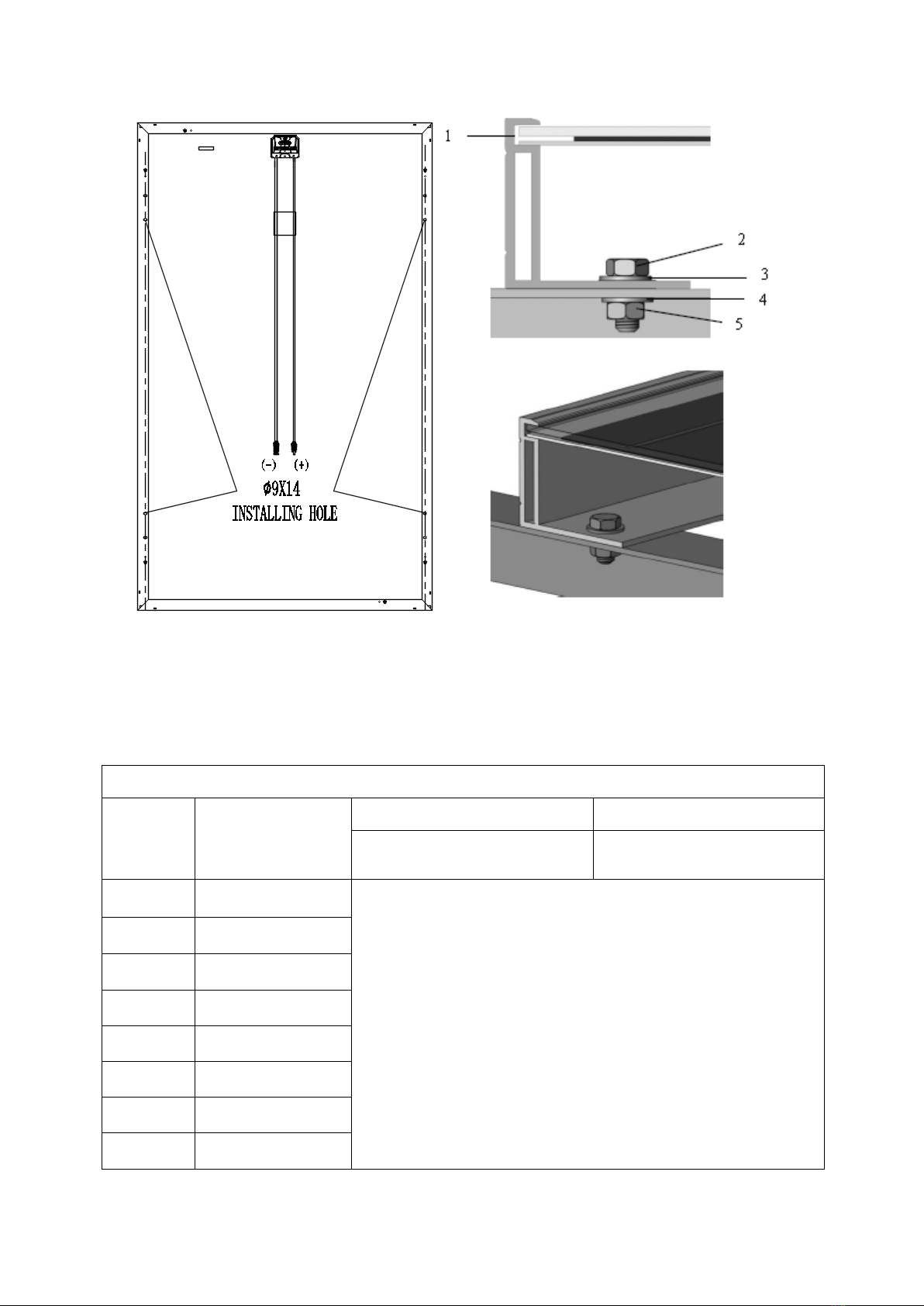
Figure 4. SPV module installed with Bolt fitting method
1 Aluminum Frame 2 M8 Stainless bolt
3 Flat Stainless Washer 4 Spring Stainless Washer
5 HEX Stainless Nut
Mounting with Bolts
NO. L*W(mm)
Load≤2400Pa Load≤5400Pa
Using 4 installation holes
with S or P holes
Using 4 installation holes
with S holes
1 1324*992
2 1640*826
3 1640*992
4 1650*992
5 1665*992
6 1665*1002
7 1684*1002
8 1775*1052

9 1956*992
10 1979*1002
11 1987*992
12 2008*1002
13 2115*1052
7 Electrical connection
7.1 Please read the electrical wiring drawings carefully before wiring, when the modules followed
the IEC standard, the maximum system voltage is 1500V DC.
7.2 The connection of module and junction box: the module is connected with junction box by a dc
cable. The cross-sectional area of cable and the connector capacity must be satisfied the
system's short circuit current (the cable's cross-sectional area for a single module is
recommended to be 4mm2, The outer diameter of the cable could be selected 5-7mm. The fuse
current and the rated current of the connector should be higher than 15A.) Otherwise, the cables
and connectors will overheat due to high current. Please note that the highest temperature of
cable is 90 ℃, and the highest temperature of connector is 125 ℃.
7.3 Aluminum frame and brackets of modules must be grounded with four ground holes of each
module, which is marked on frames (it is recommended that each series/parallel of modules
should be grounded once). The specific location of the grounding holes can be seen as the figure
below. The ground wire and frame will be reliable grounding through the reserve grounding holes,
by the installation bolts M5X10 ~ 15 matching plain washers, spring washers and nuts. Modules
and ground cables shall be connected perfectly by wiring nose. Negative grounded inverters can
be installed to prevent PID phenomenon.
7.4 Where common grounding hardware (nuts, bolts, star washers, spilt-ring lock washers, flat
washers and the like) is used to attach a listed grounding/bonding device, the attachment must be
made in conformance with the grounding device manufacturer's instructions.
7.5 Common hardware items such as nuts, bolts, star washers, lock washers and the like have not
been evaluated for electrical conductivity or for use as grounding devices and should be used only

for maintaining mechanical connections and holding electrical grounding devices in the proper
position for electrical conductivity. Such devices, where supplied with the module and evaluated
through the requirements in UL 1703, may be used for grounding connections in accordance with
the instructions provided with the module.
7.6 The electrical connection shall conform to local electrical laws and regulations, "Y" type
electrical connection mode is not allowed in module system electrical connection.
7.7 Modules are equipped with bypass diodes(rated voltage 45V, rated current 20A); improper
installation may damage diodes, cables or wiring box.
7.8 Please wrap the connectors after taking out the modules without immediate installation so as
to prevent damage caused by wind or rain. Use of lubricant for connectors is prohibited, because
it leads fracture of connectors.

7.9 Do not remove the waterproof rubber rings out of the junction box or connectors.
7.10 Use of diesel oil for heating is strictly prohibited at installation site, which may lead to
connector failure because the gas after combustion of diesel and other petroleum products.
8 Maintenance
8.1Modules need to be inspected and maintained regularly, check all electrical connections to
ensure that there is no open circuit and well connected.
8.1.1 Check the open circuit voltage of each module:
8.1.2 Covered the modules completely by non-transparent material.
8.1.3 Disconnect the wire terminals
8.1.4 Remove the non-transparent material off the modules; check and measure the terminal
open circuit voltage.
8.1.5 If the measured voltage is reduced by 1/4, it supposed to be bypass diode damaged. Please
test the bypass diode performance.
8.2 It’s recommend that adopt the following maintenance to ensure the modules maintain the best
performance:
8.2.1 Check whether the modules have appearance defects: whether the surface of the modules
are damaged or abnormal, whether the modules are occluded by objects, whether the fixing
between the modules and the frame is loose or not, and contact qualified or experienced
maintenance personnel to adjust or repair after finding the abnormalities.
8.2.2 Clean modules once a year as much as possible, depending on local conditions. When dirt
appears on the surface of modules, it will reduce the power generation. When cleaning, a soft
sponge or a rag can be used to wet the glass surface of the modules. A mild, non-abrasive
detergent can be used to remove fouling. The use of corrosive chemical cleaners is strictly
prohibited. In order to reduce electric shock or burns, it is recommended to clean modules in the
morning or evening.
8.2.3 Mechanical and electrical checks are required every six months to ensure the modules’
connectors clean and reliable connected.And ensure good electrical connection and no corrosion.
8.2.4 It need ask qualified person to check the modules if have any doubt on the modules.
8.2.5 Please note that all maintenance instructions, such as brackets, charging rectifier, inverters

and batteries, shall be complied.
9 Meaning of crossed –out wheeled dustbin:
Do not dispose of electrical appliances as unsorted municipal waste, use separate collection
facilities.
Contact your local government for information regarding the collection systems available.
If electrical appliances are disposed of in landfills or dumps, hazardous substances can leak into
the groundwater and get into the food chain, damaging your health and well-being.
When replacing old appliances with new ones, the retailer is legally obligated to take back your old
appliance for disposals at least free of charge.
10 Disclaimer of Liability
Because the use of the manual and the conditions or methods of installation, operation, use and
maintenance of photovoltaic (PV) product are beyond the control of Lianyungang Shenzhou New
Energy Co.,Ltd. We do not accept responsibility and expressly disclaims liability for loss, damage,
or expense arising out of or in any way connected with such installation, operation, use or
maintenance.
No responsibility is assumed by Lianyungang Shenzhou New Energy Co.,Ltd. for any
infringement of patents or other rights of third parties, which may result from use of the PV product.
NO license is granted by implication or otherwise under any patent or patent rights.
The information in this manual is based on our knowledge and experience and is believed to be
reliable, but such information including product specification (without limitations) and suggestions
do not constitute a warranty, expresses or implied. We reserve the right to change the manual, the
PV produce, the specifications, or product information sheets without prior notice
Table of contents
Popular Control Unit manuals by other brands


Erreka
Erreka SMART-D201 Quick installation guide

Allen-Bradley
Allen-Bradley FLEX I/O PROFIBUS 1794-APBDPV1 user manual

Henco
Henco HENCOLOGIC CU-6ZONEB-HC quick start guide

Lovato
Lovato T-FAST ie60 Assembling instructions and maintenance

Comelit
Comelit UT9331 Technical manual
 ADDENDUM 8505017 REV B... manual")
TJERNLUND
TJERNLUND UC1 UNIVERSAL CONTROL (VERSION X.06) ADDENDUM 8505017 REV B... manual