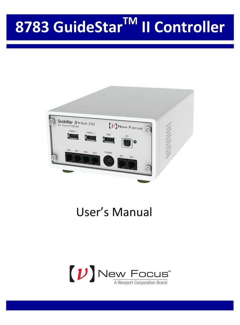
New Focus Picomotor 8742 User manual

Model8742Picomotor™Controller/Driver
QuickStartGuide
Package Contents:
This package contains the following components:
Model 8742 includes (1) Controller and (1) USB Flash Drive
Model 8742-4-KIT includes (1) Controller (1) USB Flash Drive, (1) Power Supply, and (1) USB Cable
Model 8742-8-KIT and 8742-12-KIT includes (2 or 3) Controllers (1) USB Flash Drive, (1) Power
Supply, (1) USB Cable, (1 or 2) DC Power Cables, (1 or 2) RS-485 Jumper Cables, and (1 or 2)
Stacking Plate Kits (see chart on page 13)
This Quick Start Guide
Getting Started:
Before operating this device, refer to the Model 8742 User’s Manual, starting with the section on Safety
Precautions. The complete User’s Manual is available in electronic format (PDF file). It is included in this
product’s USB flash drive, and is automatically installed on your computer’s hard drive during software
installation. Additionally, the latest version of the User’s Manual can be found at www.Newport.com on
the product’s web page.
Safety:
The Model 8742 User’s Manual contains numerous safety warnings and cautions. The user must read it
prior to applying power to the Model 8742 Picomotor™ Controller / Driver.
Voltages of up to 130 V are accessible inside the Controller and Picomotors™ devices. DO NOT operate
with the Controller cover removed. If the wire of a Picomotor™ is damaged, discontinue use and return it
for repair. If the device is used in a manner not specified by New Focus, the protection provided by the
device may be impaired.
Power should not be applied to either item by unqualified or untrained personnel.
Software Information:
The root folder of the USB flash drive contains a ReadMe.PDF file and the setup program to install the
software. To install the USB driver and software, double-click on SETUP.EXE file.
Follow the on-screen instructions to complete the installation process. For more information refer to the
8742’s ReadMe.PDF file contained on the USB flash drive.
A Newport Corporation Brand

Model 8742 Series Quick Start Guide 90066735 Rev. E Page 2 of 16
EU27 DECLARATION OF CONFORMITY
Application of Council Directive(s):
☒ Electromagnetic Compatibility Directive (EMCD) – 2014/30/EU
☒ Low Voltage Directive (LVD) – 2014/35/EU
☒ Restriction of Hazardous Substances Directive (RoHS2) – 2011/65/EU (2)
☒ Restriction of Hazardous Substances Directive (RoHS3) – (EU) 2015/863 (2)
☒ Waste Electrical and Electronic Equipment – Directive 2012/19/EU
Standard(s) to which conformity is declared:
☒ EN 61326-1:2013 – (EMC)
☒ EN 61010-1:2010 + AMD 1:2016 (Ed 3) – (Safety)
Emissions:
☒ CISPR 11:2015 Industrial, Scientific and Medical Equipment Radio-Frequency Disturbance
Characteristics - Limits and Methods of Measurement
☒ IEC 61000-3-2:2018 EMC/Limits for Harmonic Current Emission (1)
☒ IEC 61000-3-3:2013 + AMD1:2017 EMC/Limitations of Voltage Fluctuations and Flicker in Low-Voltage
Supply Systems (1)
Immunity:
☒ IEC 61000-4-2:2008 EMC/Electrostatic Discharge Immunity Test
☒ IEC 61000-4-3:2006+AMD1:2007+AMD2:2010 EMC/Radiated Radio - Frequency Electromagnetic Field
Immunity Test
☒ IEC 61000-4-4:2012 EMC/Electrical Fast Transient/Burst Immunity Test
☒ IEC 61000-4-5:2014 + AMD 1:2017 EMC/Surge Immunity Test (1)
☒ IEC 61000-4-6:2013 EMC/Conducted Disturbances induced by Radio Frequency Fields Immunity Test
☒ IEC 61000-4-8:2009 EMC/Power Frequency Magnetic Field Immunity Test
☒ IEC 61000-4-11:2004 + AMD 1:2017 EMC/Voltage Dips, Short Interruptions and Variations Immunity Test (1)
Manufacturers Name: MKS Instruments, Inc., 2 Tech Drive, Andover, MA 01810 USA
Authorized Representatives Name & Location: MICRO-CONTROLE Spectra-Physics S.A.S., Zone
Industrielle, 45340 Beaune la Rolande, France
Equipment Type/Description: Electrical equipment for measurement, control and laboratory use
Model Number(s) (1): 8742, 8742-Various
The object of the declaration described above is in conformity with the relevant Community harmonization
legislation. MKS product conforms to the above Directive(s) and Standard(s) only when installed in accordance with
manufacturer’s specifications. This declaration has been issued under the sole responsibility of the manufacturer.
Date: 1/5/2021 Signature:
Full Name: Le Cointe Hervé
Title: Quality director
==========================================================================================================================================
1) Compliance of the above model numbers requires the use of a braided shielded cable properly terminated at both ends – if so noted in the
MKS Instruction Manual.
2) RoHS Directive has to be checked for in scope products; cannot CE mark without compliance to RoHS. RoHS Directive can be
unchecked only for systems which MKS sells which qualify for “Large Scale Industrial Tool” exclusion.

Model 8742 Series Quick Start Guide 90066735 Rev. E Page 3 of 16
UK DECLARATION OF CONFORMITY
Application of Council Directive(s):
☒ Electromagnetic Compatibility Directive (EMCD) – 2014/30/EU
☒ Low Voltage Directive (LVD) – 2014/35/EU
☒ Restriction of Hazardous Substances Directive (RoHS2) – 2011/65/EU (2)
☒ Restriction of Hazardous Substances Directive (RoHS3) – (EU) 2015/863 (2)
☒ Waste Electrical and Electronic Equipment – Directive 2012/19/EU
Standard(s) to which conformity is declared:
☒ BS EN 61326-1:2013 – (EMC)
☒ BS EN 61010-1:2010 + AMD 1:2016 (Ed 3) – (Safety)
Emissions:
☒ CISPR 11:2015 Industrial, Scientific and Medical Equipment Radio-Frequency Disturbance
Characteristics - Limits and Methods of Measurement
☒ IEC 61000-3-2:2018 EMC/Limits for Harmonic Current Emission (1)
☒ IEC 61000-3-3:2013 + AMD1:2017 EMC/Limitations of Voltage Fluctuations and Flicker in Low-Voltage
Supply Systems (1)
Immunity:
☒ IEC 61000-4-2:2008 EMC/Electrostatic Discharge Immunity Test
☒ IEC 61000-4-3:2006+AMD1:2007+AMD2:2010 EMC/Radiated Radio - Frequency Electromagnetic Field
Immunity Test
☒ IEC 61000-4-4:2012 EMC/Electrical Fast Transient/Burst Immunity Test
☒ IEC 61000-4-5:2014 + AMD 1:2017 EMC/Surge Immunity Test (1)
☒ IEC 61000-4-6:2013 EMC/Conducted Disturbances induced by Radio Frequency Fields Immunity Test
☒ IEC 61000-4-8:2009 EMC/Power Frequency Magnetic Field Immunity Test
☒ IEC 61000-4-11:2004 + AMD 1:2017 EMC/Voltage Dips, Short Interruptions and Variations Immunity Test (1)
Manufacturers Name: MKS Instruments, Inc., 2 Tech Drive, Andover, MA 01810 USA
Authorized Representatives Name & Location: MICRO-CONTROLE Spectra-Physics S.A.S., Zone
Industrielle, 45340 Beaune la Rolande, France
Equipment Type/Description: Electrical equipment for measurement, control and laboratory use
Model Number(s) (1): 8742, 8742-Various
The object of the declaration described above is in conformity with the relevant Community harmonization
legislation. MKS product conforms to the above Directive(s) and Standard(s) only when installed in accordance with
manufacturer’s specifications. This declaration has been issued under the sole responsibility of the manufacturer.
Date: 1/5/2021 Signature:
Full Name: Le Cointe Hervé
Title: Quality director
==========================================================================================================================================
1) Compliance of the above model numbers requires the use of a braided shielded cable properly terminated at both ends – if so noted in the
MKS Instruction Manual.
2) RoHS Directive has to be checked for in scope products; cannot UKCA mark without compliance to RoHS. RoHS Directive can
be unchecked only for systems which MKS sells which qualify for “Large Scale Industrial Tool” exclusion.

Model 8742 Series Quick Start Guide 90066735 Rev. E Page 4 of 16
Confidentiality & Proprietary Rights
Reservation of Title
The New Focus programs and all materials furnished or produced in connection with them
("Related Materials") contain trade secrets of New Focus and are for use only in the
manner expressly permitted. New Focus claims and reserves all rights and benefits
afforded under law in the Programs provided by New Focus.
New Focus shall retain full ownership of Intellectual Property Rights in and to all
development, process, align or assembly technologies developed and other derivative work
that may be developed by New Focus. Customer shall not challenge, or cause any third
party to challenge the rights of New Focus.
Preservation of Secrecy and Confidentiality and Restrictions to Access
Customer shall protect the New Focus Programs and Related Materials as trade secrets of
New Focus, and shall devote its best efforts to ensure that all its personnel protect the New
Focus Programs as trade secrets of New Focus. Customer shall not at any time disclose
New Focus's trade secrets to any other person, firm, organization, or employee that does
not need (consistent with Customer's right of use hereunder) to obtain access to the New
Focus Programs and Related Materials. These restrictions shall not apply to information
(1) generally known to the public or obtainable from public sources; (2) readily apparent
from the keyboard operations, visual display, or output reports of the Programs; 3)
previously in the possession of Customer or subsequently developed or acquired without
reliance on the New Focus Programs; or (4) approved by New Focus for release without
restriction.
Trademarks
The New Focus logo and name are registered trademarks of Newport Corporation in
Mexico, Israel, Singapore, European Union, Taiwan, Hong Kong, China, Japan, Korea,
Canada, Australia, and the United States.
Service Information
This section contains information regarding factory service for the source. The user should
not attempt any maintenance or service of the system or optional equipment beyond the
procedures outlined in this manual. Any problem that cannot be resolved should be
referred to New Focus.

Model 8742 Series Quick Start Guide 90066735 Rev. E Page 5 of 16
1 Safety Precautions
1.1 Definitions and Symbols
The following terms and symbols are used in this documentation and also
appear on the Model 8742 Controller/Driver where safety-related issues
occur.
1.1.1 General Warning or Caution
General Warning or Caution Symbol
The Exclamation Symbol in the figure above appears on the product and in
Warning and Caution tables throughout this document. This symbol
designates that documentation needs to be consulted to determine the nature
of a potential hazard, and any actions that have to be taken.
1.1.2 Electric Shock
Electrical Shock Symbol
The Electrical Shock Symbol in the figure above appears throughout this
manual and on the product. This symbol indicates a hazard arising from
dangerous voltage. Any mishandling could result in irreparable damage to
the equipment, and personal injury or death.
1.1.3 Potential Burn Hazard
Hot Surface Symbol
The Hot Surface Symbol in the figure above appears throughout this manual
and on the product. This symbol indicates a hazard arising from a high
temperature. Any mishandling could result in personal injury.

Model 8742 Series Quick Start Guide 90066735 Rev. E Page 6 of 16
1.1.4 European Union CE Mark
CE Mark
The presence of the CE Mark on New Focus equipment means that this
instrument has been designed, tested and certified compliant to all applicable
European Union (CE) regulations and recommendations.
1.1.5 UKCA Mark
UKCA Mark
The presence of the UKCA Mark on New Focus equipment means that this
instrument has been designed, tested and certified compliant to all applicable
United Kingdom regulations and recommendations.
1.1.6 Alternating voltage symbol
Alternating Voltage Symbol
This international symbol implies an alternating voltage or current.
1.1.7 On
I
On Symbol
The symbol in the figure above represents a power switch position on a
Model 8742. This symbol represents a Power On condition.
1.1.8 Off
Off Symbol
The symbol in the figure above represents a power switch position on the
Model 8742. This symbol represents a Power Off condition.
~

Model 8742 Series Quick Start Guide 90066735 Rev. E Page 7 of 16
1.1.9 Ground
Ground Symbol
The symbol in the figure above appears on the Model 8742 to indicate the
screw to be used to ground the case of the unit. This symbol identifies the
frame or chassis terminal.
1.1.10 DC Symbol
DC Symbol
This international symbol implies an unvarying current or voltage.
1.1.11 Waste Electrical and Electronic Equipment (WEEE)
WEEE Directive Symbol
This symbol on the product or on its packaging indicates that this product
must not be disposed with regular waste. Instead, it is the user responsibility
to dispose of waste equipment according to the local laws. The separate
collection and recycling of the waste equipment at the time of disposal will
help to conserve natural resources and ensure that it is recycled in a manner
that protects human health and the environment. For information about
where the user can drop off the waste equipment for recycling, please contact
your local New Focus representative.

Model 8742 Series Quick Start Guide 90066735 Rev. E Page 8 of 16
1.1.12 Control of Hazardous Substances
RoHS Compliant Symbol
This label indicates the products comply with the EU Directive 2002/95/EC
that restricts the content of six hazardous chemicals.
1.2 Warnings and Cautions
The Model 8742 is a component of a system that will contain one or more
Picomotors and other items. Since New Focus cannot control these other
system components, the User is ultimately responsible for ensuring that the
complete system meets all applicable product and workplace safety
regulations. Specific attention should be directed to the description of safety
grounding concerns described in Section 1.3, below.
The following are definitions of the Warnings, Cautions and Notes that are
used throughout this manual to call your attention to important information
regarding your safety, the safety and preservation of your equipment or an
important tip.
WARNING
Situation has the potential to cause bodily harm or death.
CAUTION
Situation has the potential to cause damage to property or
equipment.
NOTE
Additional information the user or operator should consider.
Situation has the potential to cause the product to not comply
with applicable European Union regulations.

Model 8742 Series Quick Start Guide 90066735 Rev. E Page 9 of 16
Situation has the potential to cause the product to not comply
with applicable United Kingdom regulations.
1.2.1 General Warnings
Observe these general warnings when operating or servicing this equipment:
Heed all warnings on the unit and in the operating instructions.
Do not use this equipment in or near water.
Although the input power to this equipment is below 20 VDC, this equipment
internally generates much higher voltages that are present on the Model 8742
connector pins. Only properly trained personnel should touch either of these
items.
The Model 8742 is intended to be used as a component in a larger system.
When this product is included as part of a larger assembly, the user MUST
ensure that appropriate additional safety and EMC-compliance features are
incorporated the assembly.
The Model 8742 is typically supplied with an external DC power source. When
the external power source is connected to MAINS power, the external power
source’s detachable power cord may be used to disconnect power to the 8742.
Do not position the external power supply so that its MAINS power cord cannot
be easily disconnected.
Disconnect power before cleaning the equipment. Do not use liquid or aerosol
cleaners; use only a damp lint-free cloth.
Lockout all electrical power sources before servicing the equipment.
There are no user-replaceable fuses in this equipment. The user must ensure
that appropriate current-limiting protection is provided by the external DC
power source.
To avoid explosion, do not operate this equipment in an explosive atmosphere.
Qualified service personnel should perform safety checks after any service.
Use only the New Focus-supplied MAINS power cord with the external DC
supply. Use of under-rated power cords and cause property damage
1.2.2 General Cautions
Observe these cautions when operating this equipment:
If this equipment is used in a manner not specified in this manual, the protection
provided by this equipment may be impaired.
Do not block ventilation openings.
Use only the specified replacement parts.
Follow precautions for static sensitive devices when handling this equipment.
This product should only be powered as described in the manual.
There are no user-serviceable parts inside the Model 8742 Picomotor Drive
Module.

Model 8742 Series Quick Start Guide 90066735 Rev. E Page 10 of 16
1.2.3 Summary of Warnings and Cautions
The following general warning and cautions are applicable to this instrument:
WARNING
The Picomotor Controller/Driver is incomplete in constructional
features and is considered only to be a component for the
purposes of regulatory compliance. It is “equipment for building
in;” a suitable enclosure must be provided so that the unit is not
user accessible when incorporated into the final product.
WARNING
The Model 8742 Picomotor Controller/Driver internally generates
non-SELV voltages. These voltages are present, at times, on the
Picomotor connectors even when a Picomotor is not connected.
The user shall mount the Model 8742 with appropriate barriers,
spacings, markings, etc. to ensure that all applicable regulatory
requirements are met. THIS IS THE USER’S RESPONSIBILITY.
WARNING
Do not attempt to operate this equipment if there is evidence of
shipping damage or you suspect the unit is damaged. Damaged
equipment may present additional hazards to you. Contact New
Focus technical support for advice before attempting to plug in
and operate damaged equipment.
WARNING
The Model 8742 is intended for use ONLY with New Focus
Picomotors. Connection of other devices to the unit’s motor
connectors may cause damage to the unit or the connected
device, fire, and/or personal injury.
WARNING
Before operating the Model 8742 Picomotor Driver, please read
and understand all of Section 1.
WARNING
Do not attempt to operate this equipment if there is evidence of
shipping damage or you suspect the unit is damaged. Damaged
equipment may present additional hazards to you. Contact New
Focus technical support for advice before attempting to plug in
and operate damaged equipment.

Model 8742 Series Quick Start Guide 90066735 Rev. E Page 11 of 16
WARNING
Do not apply external DC power to this equipment in excess of
14.5 VDC.
WARNING
Use only the New Focus-supplied MAINS power cord with the
external DC power supply. Use of an under-rated power cord
may cause damage to the product, fire, and/or personal injury.
WARNING
Before cleaning the enclosure of the 8742 Controller/Driver, the
power cord must be disconnected from the wall socket and from
the unit.
CAUTION
There are no user serviceable parts inside the Model 8742
Picomotor Controller/Driver. Work performed by persons not
authorized by New Focus will void the warranty.
WARNING
If this equipment is used in a manner not specified in this
manual, the protection provided by this equipment may be
impaired.
WARNING
This instrument is intended for use by qualified personnel who
recognize thermal, shock, or laser hazards and are familiar with
safety precautions required to avoid possible injury. Read the
instruction manual thoroughly before using, to become familiar
with the instrument’s operations and capabilities.
CAUTION
The Model 8742 Picomotor Controller/Driver is designed to be
safe when operated under Normal Environmental Conditions as
defined in EN61010-1:2010. Operation under harsher
environmental conditions can result in severe injury.

Model 8742 Series Quick Start Guide 90066735 Rev. E Page 12 of 16
CAUTION
The case of the Model 8742 Picomotor Controller/Driver is used
to dissipate internally-generated heat. Blocking the normal
convective airflow around the unit, or thermally insulating the
unit, can result in severe injury, damage to the product, and/or
fire.
CAUTION
When operated at higher pulse rates for extended periods of
time, the temperature on the outside of the Model 8742’s case
may rise above the “surface temperature limits in normal
operation” as defined in EN61010-1:2010 unless the user takes
appropriate measures. These may include the addition of an
external heat sink, barriers to contact, reducing the pulse
frequency, or other appropriate mitigations. Failure to take
appropriate action when operating the Model 8742 under these
conditions can result in severe injury.
CAUTION
The case of the Model 8742 Picomotor
Controller/Driver is used to dissipate
internally-generated heat. Blocking the
normal convective airflow around the unit,
or thermally insulating the unit, can result
in severe injury, damage to the product,
and/or fire.
The Model 8742 Picomotor Controller/Driver is intended for use
in an industrial laboratory environment. Use of this product in
other environments, such as residential, may result in
electromagnetic compatibility difficulties due to conducted as
well as radiated disturbances.
The Model 8742 Picomotor Controller/Driver is intended for use
in an industrial laboratory environment. Use of this product in
other environments, such as residential, may result in
electromagnetic compatibility difficulties due to conducted as
well as radiated disturbances.

Model 8742 Series Quick Start Guide 90066735 Rev. E Page 13 of 16
1.3 Safety Grounding Considerations
There are potentially lethal voltages generated with the Model 8742
Picomotor Controller/Driver and presented on the pins of the “Motor”
connectors EVEN WHEN NO PICOMOTOR IS INSTALLED. (These
voltages are not present when power is not applied to the unit; they also are
not present when the unit is switched OFF.) The User must manage certain
system-level aspects to ensure safe operation. One of these is grounding.
The Model 8742’s external DC power supply provides 12VDC. The negative
output from this supply is typically isolated from MAINS earth ground, but
this isolation should not be assumed. This same negative output is connected
directly to the Model 8742’s external case within the Model 8742. This same
“ground” is at the same potential as the MOTOR connectors’ return signal
pins. This means that the MOTOR connectors’ drive signal pins are, at
times, at VERY HIGH VOLTAGES relative to the Model 8742 case, the
USB connector shell, and the DC input/loop-through connectors’ negative
terminals.
An 8-32 screw is provided on the unit and marked with the “Ground” symbol
shown in Paragraph 1.1.9, above. While it is not necessary to connect this
terminal to a building “earth” ground, New Focus recommends doing so
because it will simplify system-level compliance with most regulatory
requirements. Once this connection is made, the user must ensure that all
other system components are appropriately grounded. If the other
components are not grounded, a damaged Picomotor (or its wire) could result
in a dangerously high voltage being present between anything that is
grounded (like the 8742 and a computer attached to it via USB) and the
picomotor case. Note that the simplest way to ground a Picomotor is via its
threaded mounting bushing or other mounting hardware. DO NOT
ATTEMPT TO OPEN A PICOMOTOR TO ACHIEVE THIS
GROUNDING.
If system requirements prevent the Picomotor from being grounded, then the
user must ensure that the Model 8742 and all other system components
(including any USB-connected computers) are properly isolated from earth
ground. This is because a short of the high-voltage drive signal to an earth
ground may result in potentially lethal voltages existing between the case of
the 8742 and anything that is earth grounded, such as a floor. The User is
advised to consult all applicable regulations because this insulation will
probably need to have a breakdown voltage of several thousand volts due to
lightening concerns.
In summary, New Focus strongly recommends grounding the Model 8742’s
case.

Model 8742 Series Quick Start Guide 90066735 Rev. E Page 14 of 16
1.4 Model 8742 Series Kits and Accessories
The following are available kits and accessories:
Power supply/AC adapter, 60 Watt (Model 8745-PS)
Power supply link cable, 6 inch, for daisy chaining multiple controllers together
using a single 12 VDC supply (Model 8745-PWR-CBL)
RS-485 LAN link cable, 6 inch, for daisy-chaining (Model 8745-RS485-CBL)
USB cable, 3 meter (Model 8745-USB-CBL)
L-shaped bracket for stacking several units (Model 8745-STK-KIT)
Optical table mounting plate kit (Model 8745-MTG-KIT)
8-Axis Ki
t
12-Axis Ki
t
8745-USB-CBL
8745-PS
8745-PWR-CBL
8745-PWR-CBL
8745-ST
K
-KIT
8745-ST
K
-KIT
Model 8742-12-KIT
8745-USB-CBL
8745-PS
8745-PWR-CBL
8745-ST
K
-KIT
Model 8742-8-KIT
4-Axis Ki
t
8745-PS
Model 8742-4-KIT
8745-USB-CBL
Model 8742
8742
8742
8742
8742 8742
8742
8742
8742 Onl
y
8745-RS485-CBL
8745-RS485-CBL
8745-RS485-CBL

Model 8742 Series Quick Start Guide 90066735 Rev. E Page 15 of 16
1.5 Stacking and Interconnecting Units
The following figure demonstrates how multiple controllers are typically
stacked and i98nterconnected using standard available accessories:

Model 8742 Series Quick Start Guide 90066735 Rev. E Page 16 of 16
1.6 RS-485 Local Area Network (LAN) Connectivity
If several units need to be controlled via Ethernet or USB, they do not all
have to be connected directly to the PC or an Ethernet Switch or USB Hub.
Instead, a single unit can act as a “gateway” or “master” by connecting it to
the PC and also connecting it to the remaining units using a half-duplex RS-
485 LAN bus.
There are two RS-485 connectors that accept standard 3.5mm stereo plugs.
The two connectors are connected in parallel inside the controller. These
connections along with RS-485 cable (model 8745-RS485-CBL) facilitate
daisy-chain type hook-up to simplify the wiring between an external
computer and multiple controller units.
Read controller User’s Manual for complete details.
NOTE: Make sure RS-485 cable plug is fully inserted into controller
connector input socket.
NOTE: Install and run easy to use Picomotor Windows application
software to confirm USB, Ethernet and RS-485 LAN communication.
Newport Corporation U.S.A
Office: 800-222-6440
P/N: 90066735 Rev. E
Table of contents
Other New Focus Controllers manuals
Popular Controllers manuals by other brands

ProMinent
ProMinent DULCOMETER Compact Assembly and operating instructions
Zennio
Zennio MAXinBOX 24 v2 Technical documentation
Endress+Hauser
Endress+Hauser RMS621 operating instructions

Spectron
Spectron spectropur LE 71 user manual

Avigilon
Avigilon AC-HID-LSP-ACMEC-KIT8 installation guide
KMC Controls
KMC Controls CSC 3000 Series Application guide
Studio Technologies
Studio Technologies StudioComm 792 user guide

Bluelight Automatic Technology
Bluelight Automatic Technology BL6-DU20PX Series user manual
Fortinet
Fortinet FortiController-5913C System guide

Atmos
Atmos Multi Installation
Allen-Bradley
Allen-Bradley 1492-IFM20F-F240-2 manual
SICK
SICK Flexi Soft operating instructions
