New Focus 1480 User manual

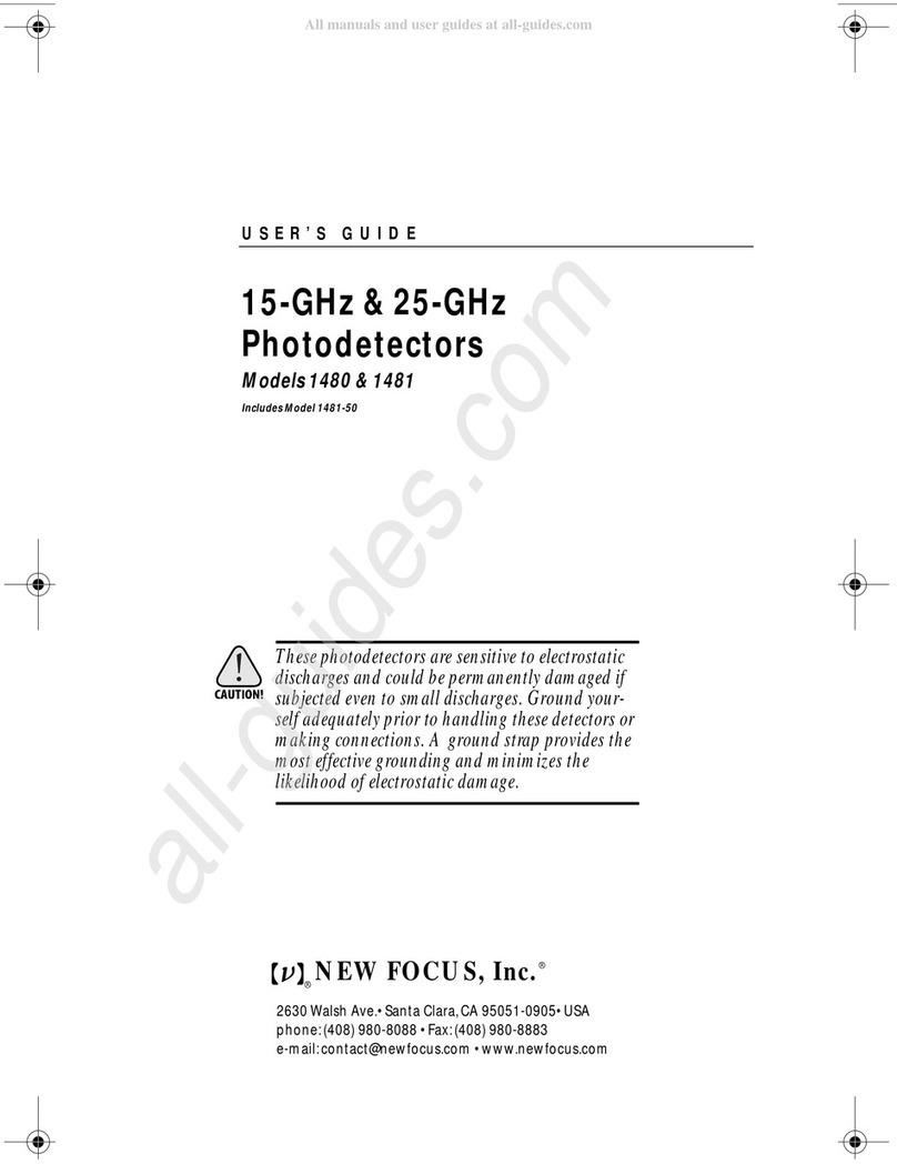
USER’S GUIDE
15-GHz & 25-GHz
Photodetectors
Models1480&1481
IncludesModel1481-50
Thesephotodetectorsaresensitivetoelectrostatic
dischargesandcouldbepermanentlydamagedif
subjectedeven to smalldischarges. Groundyour-
selfadequatelypriortohandlingthesedetectorsor
makingconnections.Agroundstrapprovidesthe
mosteffectivegroundingandminimizesthe
likelihoodofelectrostaticdamage.
NEW FOCUS, Inc.
2630Walsh Ave.• Santa Clara,CA 95051-0905• USA
phone:(408) 980-8088 • Fax:(408) 980-8883
®
®
1480 FC Det revA.fm Page 1 Monday, March 13, 2000 2:55 PM

Warranty
NewFocus,Inc. guaranteesitsproductstobefreeofdefectsforoneyear from
thedateofshipment.Thisisinlieuofallotherguarantees,expressedorimplied,
anddoes notcoverincidentalorconsequentialloss.
Copyright 2000,NewFocus,Inc.Allrights reserved.
The symbolandNEWFOCUS,Inc.are registeredtrademarks
ofNEWFOCUS,Inc.
DocumentNumber 151095Rev.A
1480 FC Det revA.fm Page 2 Monday, March 13, 2000 2:55 PM

15-GHz & 25-GHz Photodetectors Contents • 3
Contents
Operation 5
Introduction .... ..... ..... ..... ..... ..... .. ... .. ... .. .. 5
HandlingPrecautions..... ..... .. ... .. ..... ..... ..... ... 6
QuickStart.... ..... ..... ..... ..... ..... .. ... .. ..... .... 7
CheckingtheBatteryand OffsetVoltage .... ..... ..... ... 8
MakingtheMicrowaveConnection... .. ..... ..... ..... .. 9
ConnectingtheDetectorto theOpticalInput ... ..... .... 9
Characteristics 11
PhotodetectorCharacteristics ... .. ..... ..... ..... ..... . 11
Bias-MonitorCharacteristics ..... ..... ..... ..... ..... .. 12
Responsivity .. ..... ..... ..... ..... ..... ..... .. ... .. ... 12
Troubleshooting 13
TestingthePhotodiode . ..... ..... ..... ..... .. ... .. .... 13
CheckingtheDC-OffsetVoltage.. ..... ..... ..... .. ... .. 13
BasicOpticalTest.. ..... .. ... .. ... .. ..... ..... ..... .... 13
CleaningtheFiberConnector ... ..... ..... ..... ..... ... 14
CustomerService 17
TechnicalSupport.. ..... ..... ..... ..... ..... .. ... .. ... 17
Service..... ..... .. ... .. ..... ..... ..... ..... ..... ..... . 17
AppendixI:Microwave Connectors 19
AppendixII:Inside the Photodetector 20
1480 FC Det revA.fm Page 3 Monday, March 13, 2000 2:55 PM

4 • Contents NEW FOCUS, Inc.
1480 FC Det revA.fm Page 4 Monday, March 13, 2000 2:55 PM

15-GHz & 25-GHz Photodetectors Operation • 5
Operation
Introduction
High-speedmeasurementsareeasywiththe Models
1480and1481photodetectormodules.These
modulesconvertyouropticalsignalstoelectronic
signals,ineffectgivingeveryhigh-speed/high-
frequencyinstrumentinyourlabanopticalinput.
Eachmoduleconnectsdirectlytothe testinstrument
oramplifier,eliminatingtheneedforcoaxialcables,
whichcouldseriouslydistortpicosecondpulsesand
attenuatemicrowavesignals.The optical signalis
deliveredtothephotodiodeinthemodulethrougha
multimodeoptical fiber.Moreover,thephotodiode
biascircuitand batteryareself-contained,eliminating
thehassleofexternalpowersuppliesandexpensive
biasnetworksandreducingthe possibilityof
photodiodedamageduetoovervoltage.
TheModels1480and1481useaGaAsPINphotodiode
designedforhighresponsivityinthe 780–870-nm
wavelengthrange.Thehigh-speedcircuitryproducesa
cleanimpulseresponse,makingthesemodelsidealfor
digitalcommunicationmeasurements.A 50-
Ω
terminatingresistorminimizeselectricalreflections,
whichhelpstominimize ringingwhenusedwith
amplifiers whichmay nothave perfect50-
Ω
inputs.
TheModel1480hasaninternal62.5-µmmultimode
fiberwhichdeliverstheinputlighttothe65-µm-
diameterphotodiode,permittingtheuse ofdelivery
fibers with corediametersof62.5µm orsmaller,
1480 FC Det revA.fm Page 5 Monday, March 13, 2000 2:55 PM

6 • Operation NEW FOCUS, Inc.
includingsingle-modefibers.Theinternalfiberis
anglepolishedforlowbackreflection.
TheModel1481hasaninternalsingle-modefiber,
whichisanglepolishedtoreducebackreflections.The
Model1481-50hasaninternal50-µmmultimodefiber
andusesaGRINlens toimagethefiberoutputonto
the25-µmphotodiodeusedin thesemodels.The
opticalelementsareanti-reflectioncoatedforlowback
reflectionat850nm.
Figure 1:
Models
1480 & 1481
photodetector
modules
Handling Precautions
Wheneverhandlingthephotoreceiver,makesureto
followthese precautions:
• Priortohandlingthedetectorormaking
connections,besuretogroundyourself
adequately—evensmallelectrostaticdischarges
couldpermanentlydamagedthedetector.A
groundstrapprovides the mosteffective
groundingandminimizesthe likelihoodof
electrostaticdamage.
• DonotovertorquethemicrowaveK-connector.
Excessivetorquecandamage connectors.
• Makesuretheopticalconnectorisclean and
undamagedbeforeconnectingittothedetector
module.
Optical Input
Off On Batt
Chk
Bias
Monitor
FC/PC connector
for fiber optic input
Bias-monitor port—output
is equal to photodiode current
times 1000 Ω, for 1 mV/µA.
Power switch
Battery-check button—
press to apply the photo-
diode bias voltage to
the bias-monitor port.
2.00 (50.8)
2.25 (57.1)
2.00
(50.8)
Output K-connector
3.14 (79.8)
1480 FC Det revA.fm Page 6 Monday, March 13, 2000 2:55 PM

15-GHz & 25-GHz Photodetectors Operation • 7
Quick Start
UsetheModels1480and1481high-speedGaAs
photodetectormodulesfor detectinglightinthe
wavelengthrangefrom400to870nm.Eachmoduleis
50-
Ω
terminatedandhasaninternalbatteryandbias
circuitry tomakeitself-contained—noadditional
powersupplyorbias circuitryisneeded.
Tooperatethemodule,followthesequick-start
instructionsorconsulttheothersectionsofthis
manualformoredetail.
1.
Takeproperprecautionstoavoidelectrostatic
damagetothe photodiode.(See“HandlingPrecau-
tions”onpage6.)
2.
Removethemodulefromitscase.
3.
Turnonpowerusingthe“Off/On”switch.
Ifyouare usingthedetectorforthefirst time,oryou
wishtocheckthebatteryandDCoffset,performsteps
4,5and6
4.
Connectavoltmetertothe“BiasMonitor”SMA
connector.
5.
Pressthe“BattChk”button.Thevoltageshouldbe
atleast3.5V.
6.
Releasethe“BattChk”button.Withoutanoptical
input,thevoltageshouldbelessthan10mV.
7.
Connectthephotodetectormoduletoyour
measurementinstrument,beingcarefulnotto
over-torquetheK-connector.Theinstrumentmust
havea50-
Ω
inputimpedance.
8.
Checkthattheopticalpoweremergingfromyour
fiberisbelowthecwSaturationPower, as
appropriate, to ensure detectorlinearityandto
avoiddetectordamage.(See “Characteristics” on
page11
.
)
1480 FC Det revA.fm Page 7 Monday, March 13, 2000 2:55 PM

8 • Operation NEW FOCUS, Inc.
9.
Connectyouropticalfibertotheconnectoronthe
detectormodule.
10.
Whenfinishedusingthe module,turnoffthe
powertopreserve batterylife.
Ifanyofthesestepspresentproblemsoryouwould
likemoreinformation,pleaseconsulttheremainderof
thismanual.
Checking the Battery and OffsetVoltage
Thebatteryandoffsetvoltageshouldbechecked
regularlyto ensureproperfunctioningofthedetector.
1.
Turnonthemoduleusingthepowerswitch.
2.
Connectthe“Bias Monitor”porttoavoltmeter.
3.
Press andholdthe “BattChk”buttonandobserve
thebias-monitoroutput.Thephotodiodebias
voltageismomentarilyappliedtothe“Bias
Monitor”SMAconnector.Areadingof5Vonthis
connectoristypical with anewbattery; the
batteryshouldbe replaced whenthevoltage
reaches3.5V.
4.
Releasethe“BattChk”buttonandobserve the
voltagelevel onthevoltmeter.Withoutanoptical
input,thisvoltageis the DCoffsetplusdark
current. This“darkvoltage”shouldbeless than
10mV.
5.
Ifneeded, keepthevoltmeterconnectedtothe
moduletooptimizecouplingtothefiber.
Replacing the battery
1.
Turnoffthemoduleandremovethetwoscrews
onthebackpanelwithaPhillipsscrewdriver.(See
Figure1onpage6.)
2.
Removethebackpanelandreplacethebattery.
3.
Replacethebackpanel.
1480 FC Det revA.fm Page 8 Monday, March 13, 2000 2:55 PM

15-GHz & 25-GHz Photodetectors Operation • 9
4.
Checkthebatterylevelasdescribed above.
Making the Microwave Connection
1.
Connectthephotoreceivermodule’smicrowave
connector toa testinstrumentthathasa50-
Ω
input,suchasanoscilloscopeorspectrumana-
lyzer, ortoanother50-
Ω
load.Ifnecessary, usea
high-frequencycable(best performanceis
achievedwithoutacable).
2.
Toavoidconnectordamageand signaldistortion,
besurethatthecableandtheinstrumentyou
intendtoconnecttothemodulehavecompatible
connectors.See “AppendixI:Microwave
Connectors”onpage19 fora listofcompatible
connectors.
Connecting the Detector to the Optical Input
1.
Measurethepeak powerinthefiberpriortocon-
nectiontothe moduletobesureitis within the
safeoperatingrange(see“PhotodetectorCharac-
teristics”onpage11).
2.
Connectthefiber-opticcabletothe fiber-optic
inputonthedetectormodule.Ifneeded,theBias
Monitormaybeusedtooptimizecouplingtothe
fiber.
1480 FC Det revA.fm Page 9 Monday, March 13, 2000 2:55 PM

10 • Operation NEW FOCUS, Inc.
1480 FC Det revA.fm Page 10 Monday, March 13, 2000 2:55 PM

15-GHz & 25-GHz Photodetectors Characteristics • 11
Characteristics
Photodetector Characteristics
Thevaluesbelowaregivenat850nm.
Model# 1480 1481
Wavelength Range 400–870 400–870
3-dB Bandwidth 15 GHz 25 GHz
RiseTime 25 ps 15 ps
Conversion Gain 10V/W 10V/W
Responsivity 0.4 A/W 0.4 A/W
Output Impedance 50
Ω
50
Ω
Minimum NEP 45 pW/ 45 pW/
cw Saturation Power >5 mW >2 mW
Detector Material/Type GaAs/PIN GaAs/PIN
Detector Diameter 65
µ
m 25
µ
m
Input-Fiber Core Diameter
“-50”version 62.5-µm multimode
N/A 9-µm single mode
50-µm multimode
Power Requirements Internal 9-V battery Internal 9-V battery
Optical Input Connector FC/PC FC/PC
Electrical Output Wiltron K Wiltron K
Hz
Hz
1480 FC Det revA.fm Page 11 Monday, March 13, 2000 2:55 PM

12 • Characteristics NEW FOCUS, Inc.
Bias-Monitor Characteristics
Responsivity
Agraphofthe typicalandpredictedresponsivityof
theModels1480and1481isshown below.
Figure 2:
Responsivityvs.
wavelength for
Models
1480 & 1481
Model# 1480 1481
DC Gain 1 mV/µA 1 mV/µA
DC Offset (max.) 10 mV 10 mV
Output Impedance 10 k
Ω
10 k
Ω
Bandwidth 50 kHz 50 kHz
0.1
0
0.2
0.3
0.4
0.5
700600 800 900
Wavelength, nm
Responsivity, A/W
1480 FC Det revA.fm Page 12 Monday, March 13, 2000 2:55 PM

15-GHz & 25-GHz Photodetectors Troubleshooting • 13
Troubleshooting
Testing the Photodiode
Thephotodiodecan bedamagedbyelectrostatic
dischargeorexcessiveopticalpower,whichcanleadto
anincreaseddark(or
offset
)voltage.Adamaged
photodiodecan resultinadegradedresponsivity and
frequency/impulseresponse. See“CheckingtheDC-
OffsetVoltage,”below.
Checking the DC-OffsetVoltage
1.
Withnolightonthephotodetector,turnthe
detectoron.
2.
UseavoltmetertomeasuretheBiasMonitor
outputvoltage.ThisvoltageistheDC offsetplus
darkcurrent.
3.
Iftheoutputis>10mV, thenthedetectoris
probablydamaged andwill needtobereturned to
NewFocus.
Iftheoutputis<10mV, thenperformthe Basic
OpticalTestdescribedbelow.
Basic OpticalTest
Toquicklytestthephotodiodein yourreceiver,run
thissimpleDCopticaltest.
1.
Turnthereceiveron.
1480 FC Det revA.fm Page 13 Monday, March 13, 2000 2:55 PM

14 • Troubleshooting NEW FOCUS, Inc.
2.
Usingavoltmeteroroscilloscope, measurethe
outputvoltagefromtheBias Monitoronthefront
panelofthebiassupply.
Withnolightonthedetector,theBiasMonitor
voltageshouldbe <10mV.
3.
Illuminatethephotodetector.
4.
Withthevoltmeteroroscilloscope,youshould
observeaDCoutputvoltage.
Ifyouknowtheopticalpower andwavelength,
youcancalculatetheexpectedoutputvoltage
(
V
out
)usingtheexpression:
V
out
=
P
in
•
R
•
G
,where
P
in
istheinputopticalpower(watts),
R
isthe
photodetector’sresponsivity(A/W), and
G
isthe
amplifier’stransimpedancegain(V/A).Thegainof
thebiasmonitorportis1000 V/A.
Iftheoutputvoltageislow,thenthefiberconnector
maybedirty(see“CleaningtheFiberConnector,”
below). Ifyoususpecttheunit is damaged,contact
NewFocustoarrangeforarepair(see“Customer
Service”onpage17).
Cleaning the Fiber Connector
Thehigh-speedphotodetectorshavean internalfiber
connectorandafiberpigtailthatbringstheinputlight
tothe detector.If the fiberconnectorisdirty,thiscan
blocktheinputlightsothatlightsentintothedetector
will producelittleornooutputvoltage.
Notealsothatifthefibertypesarenotcompatible(e.g.
multimodetosinglemode),thiscanalsobethecause
ofaverylowoutputvoltage.
Tocleanthefiber:
1.
Turnoffthemodule.
2.
Blowfilteredairoranotherinertgas(suchas
nitrogen)intotheinputfiber connector.This will
1480 FC Det revA.fm Page 14 Monday, March 13, 2000 2:55 PM

15-GHz & 25-GHz Photodetectors Troubleshooting • 15
helptoremoveanydustordirtparticlesthat
mightbeblockingtheinputlight.
Ifmorecleaningisneeded,proceedwithsteps3-8.
3.
Wearagroundingstrap.
4.
Removethetwo screwsonthebackpanel with a
Phillipsscrewdriver.Removethebackpanel.
5.
Removethetwo screwsonthebottomofthe
detectorusinganAllenkey(1/16"or1.5-mm),and
carefullyslidethedetectorhousingoff.
Caution: Forsteps6–8,beextremelycarefulnottopullon the
fiber.Thefiber isnotdesignedtowithstandexcessivestress
whereit connectstothemicrowavehousing.
6.
Carefullydisconnectthefiberconnectorfromthe
fiberreceptacleattachedtothefrontpanelofthe
detector.
7.
Thefrontsurfaceofthefibercan be cleanedusing
acetoneor alcohol and lens tissue.
8.
Carefullyreconnectthe fibertothefrontpanel
receptacle, re-installthe detectorhousing(be
carefulnotto pinchordamagethefiber),andre-
installthe backpanel.
1480 FC Det revA.fm Page 15 Monday, March 13, 2000 2:55 PM

16 • Troubleshooting NEW FOCUS, Inc.
1480 FC Det revA.fm Page 16 Monday, March 13, 2000 2:55 PM

15-GHz & 25-GHz Photodetectors Customer Service • 17
Customer Service
Technical Support
Informationandadviceabouttheoperationofany
NewFocusproduct isavailablefromourtechnical
supportengineers.
Engineersareondutyfrom8:00–5:00 PST,Monday
throughFriday(excludingholidays).Forquickest
response, askfor“TechnicalSupport”andknowthe
modelnumberforyourreceiver.Themodelnumberis
printedonthefrontpanelofthereceiver.
Phone: (408) 980-8088
Fax:(408)980-8883
Supportisalsoavailablebyemail.
Email:techsupport@newfocus.com
Wetypicallyrespondtoemailwithinonebusinessday.
Service
Intheeventthatyourphotodetectormalfunctionsor
becomes damaged,pleasecontactNewFocusfora
returnauthorizationnumberandinstructionson
shippingtheunitbackforevaluationand repair.
1480 FC Det revA.fm Page 17 Monday, March 13, 2000 2:55 PM

18 • Customer Service NEW FOCUS, Inc.
1480 FC Det revA.fm Page 18 Monday, March 13, 2000 2:55 PM

15-GHz & 25-GHz Photodetectors Appendix I: Microwave Connectors • 19
Appendix I:Microwave Connectors
Theperformanceyouobtainfromthe Model148X
photodetectormodulesdependslargelyonthe
instrumentyouusetomeasuretheirmicrowave
outputsandhow theconnectionsaremadetothis
instrument.
Connectthemaleconnectorofthephotodetector
directlytothefemaleconnectoroftheinstrument.If
aninterveningcoaxialcableisused,makesureithas
sufficientlylowlossinthefrequencyrangeofinterest
Evenif youarenotusinganintervening cable,
performancecanbedegradedifanimproperadapteris
chosenformatingtotheinstrument.CommonSMA
connectors,forexample,areintendedforuseonlyto
18GHz.Thefollowingtablelistsafewconnectorsand
thefrequencyrangesinwhichtheymaybe used.(For
moreinformation,request ApplicationNote1.)
Connector FrequencyRange Compatibility
BNC DC–2 GHz ——
SMA DC–18 GHz Wiltron K,3.5 mm
3.5 mm DC–34 GHz SMA,Wiltron K
Wiltron K DC–40 GHz SMA,3.5 mm
2.4 mm DC–55 GHz Wiltron V
WiltronV DC–65 GHz 2.4 mm
NewFocusalsooffersthefollowingadapters:
Model1225Male-SMA toFemale-BNC
Model1226Female-SMA toMale-BNC
Model122740-GHzFlexCable,Female-KtoMale-K
1480 FC Det revA.fm Page 19 Monday, March 13, 2000 2:55 PM

20 • Appendix II: Inside the Photodetector NEW FOCUS, Inc.
Appendix II:
Inside the Photodetector
Agold-platedmicrowavehousinginsidethe
photodetectormodulecontainsthehigh-frequency
circuitry.Thishousingisboltedtoaprinted-circuit
boardwhichregulates thebiasforthephotodiodeand
amplifies theDCphotocurrentforthemonitorport.
Theopticalsignalisbroughtfromthefront-panel
connectortothemicrowave housingwith9-cm fiber.
Thefiberisprotectedbyasheetmetalflangetoprevent
damagewhilechangingthebattery.Asimplified
schematicisprovidedbelow.
Figure 3:
Simplified
schematic of
the Models
1480 & 1481
photodetector
modules
–
+
–
+
V+V-V+V-
V-
V+
V-
Microwave
Housing
Photodiode
Microwave
Output
Connector
On/Off
Batt
Chk
Bias
Monitor
1480 FC Det revA.fm Page 20 Monday, March 13, 2000 2:55 PM
Other manuals for 1480
1
This manual suits for next models
2
Table of contents
Other New Focus Security Sensor manuals
Popular Security Sensor manuals by other brands

GTV
GTV Wenud Duo LD-WENDM13W-40 manual
Bircher Reglomat
Bircher Reglomat PrimeMotion B Original instructions

SwannOne
SwannOne Motion Sensor quick start guide

MSS Professional
MSS Professional SmokeCloak VALI Series Installation and operating instruction

Sime
Sime SRS Installation and use manual
Trixell
Trixell Pixium 4600 Installation, service and user manual
