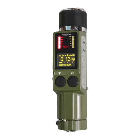
Polimaster PM1704 User manual

SPECTROSCOPIC PERSONAL RADIATION DETECTOR
РМ1704
OPERATION MANUAL

2
CONTENTS
1 GENERAL INFORMATION ........................................................................................................ 4
2 INSTRUMENT DELIVERY SET ................................................................................................. 5
3 TECHNICAL SPECIFICATIONS ................................................................................................ 6
4 EXTERNAL INSTRUMENT VIEW. CONTROL KEYS .......................................................... 12
5 LCD INFORMATION ................................................................................................................. 14
6 INSTRUMENT DESIGN AND OPERATIONAL PRINCIPLE ................................................ 15
7 SAFETY MEASURES ................................................................................................................. 17
8 CLIP MOUNTING AND DEMOUNTING ................................................................................. 17
9 INSTRUMENT POWER ............................................................................................................. 18
9.1 Place/Replace Battery and Rechargeable battery ................................................................ 18
9.2 Select battery type ................................................................................................................. 19
9.3 Rechargeable battery charging ............................................................................................ 20
10 GET THE INSTRUMENT READY FOR OPERATION ......................................................... 22
11 INSTRUMENT OPERATION .................................................................................................... 23
11.1 Instrument Operation Modes ............................................................................................. 23
11.1.1 Test Mode..................................................................................................................... 23
11.1.2 Calibration Mode ......................................................................................................... 23
11.1.3 Gamma Radiation DER Measurement Mode ............................................................ 25
11.1.4 Search Mode ................................................................................................................ 27
11.1.4.1 Detect Gamma and Neutron Radiation Sources ................................................. 28
11.1.4.2 Localization of Gamma Radiation Sources ......................................................... 30
11.1.5 Menu Indication Mode ................................................................................................ 31
11.1.6 Settings Mode............................................................................................................... 32
11.1.6.1 Instrument Information ....................................................................................... 32
11.1.6.2 History Setting Mode ........................................................................................... 33
11.1.6.3 Alarms On/Off ...................................................................................................... 33
11.1.6.4 Display Settings Configuration ............................................................................ 34
11.1.6.5 Select Battery Type .............................................................................................. 34
11.1.6.6 Set Instrument Date and Time............................................................................. 35
11.1.6.7 Set Volume of Sound Alarm ................................................................................ 35
11.1.6.8 Search Function On/Off in Measurement Mode. Select measurement units ..... 36
11.1.6.9 Set Identification Parameters .............................................................................. 36
11.1.7 Threshold Setting Mode ............................................................................................... 37
11.1.8 Scintillation Spectra Registration Mode ..................................................................... 39
11.1.8.1 Scintillation Spectra Accumulation ..................................................................... 40
11.1.8.2 View Mode of Saved Scintillation Spectra........................................................... 44
11.1.8.3 Select of reference source for autocailbration ..................................................... 45
11.1.8.4 Autocalibration .................................................................................................... 45
11.1.9 Reset of statistics .......................................................................................................... 46
11.1.10 Mode of Quick Identification of Radionuclide isotope composition ........................ 46
11.1.10.1 Manual Start of Quick Identification of Radionuclide isotope composition
Mode ................................................................................................................................... 47
11.1.10.2 Automatic Start of Mode of Radionuclide isotope composition Identification 48
11.1.11 PC Communication Mode ......................................................................................... 48
12 TECHNICAL MAINTENANCE ............................................................................................... 50
13 POSSIBLE FAULTS .................................................................................................................. 50
14 VERIFICATION METHOD ..................................................................................................... 51
15 STORAGE AND TRANSPORTATION ................................................................................... 55
16 DISPOSAL.................................................................................................................................. 55

3
Thank You for purchasing Spectroscopic Personal Radiation Detector РМ1704
(РМ1704GN, РМ1704М) manufactured by Polimaster.
Please, carefully study current Operation Manual before working with Spectroscopic Personal
Radiation Detector PМ1704 (РМ1704GN, РМ1704М) (further instrument) to prevent wrong actions
and provide safe instrument operation.
Operation Manual contains key technical specifications of the instrument, operation and
maintenance guidelines, metrological examination as well as other necessary information on correct
instrument operation and full utilization of its capabilities1.
1 Documented instruments and their electric circuit, internal and external design, as well as software are subject to change in the
manufacturing process with no substantial effect on their functionality, technical and metrological performance. Hence, Polimaster reserves
the right not to mention it in the current Operation Manual.

4
1 GENERAL INFORMATION
Spectroscopic Personal Radiation Detectors РМ1704, PM1704GN, РМ1704М are designed to
identify radionuclide isotope composition, measure ambient dose equivalent rate
H
*(10) (further DER)
of gamma radiation, accumulate and store gamma radiation scintillation spectra, search (detect and
locate) sources of radioactive and nuclear sources.
Instruments are produced in three versions:
- Spectroscopic Personal Radiation Detector PM1704;
- Spectroscopic Personal Radiation Detector PM1704GN. This instrument is equipped with
neutron radiation detector, unlike the Spectroscopic Personal Radiation Detector РМ1704;
- Spectroscopic Personal Radiation Detector РМ1704М. DER measurement range of this
instrument is more expanded as one of PM1704.
Instrument belongs to the family of portable measuring instruments of ionizing radiation that can
be operated in laboratories and field conditions. Instrument can be used by radiological and isotope
tracing laboratories, emergency services, customs officers to identify radionuclide isotope compositions,
measure DER of gamma radiation, search of ionization sources so that to prevent unauthorized transfer
of radioactive sources and materials. Instrument is as well used by specialists engaged in different
industry branches, agriculture, transport, medicine and so on, i.e. everywhere where nuclear-engineering
facilities and ionizing radiation sources are used.
Instrument is designed to operate in the following conditions:
- operation temperature range from -20 oС to 50 oС;
- relative air humidity at
40 oС and lower up to 98 %;
- atmospheric pressure from 84 kPa to 106.7 kPa.

5
2 INSTRUMENT DELIVERY SET
Instrument delivery set corresponds to Table 2.1.
Table 2.1
Description Quantity, pcs.
PМ1704 РМ1704GN РМ1704М
Spectroscopic Personal Radiation Detector
PМ1704 1 - -
Spectroscopic Personal Radiation Detector
РМ1704GN - 1 -
Spectroscopic Personal Radiation Detector
РМ1704М - - 1
Battery
1)
1 1 1
Certificate 1 1 1
Quick start 1 1 1
Data storage (Operation Manual
2)
, User
Guide) 1 1 1
Package 1
1)
Battery (Alkaline) 1.5 V, no less than 2000 mA
h, AA (LR6
), or rechargeable NiMH battery no less
than 2500 mAh. Other batteries with similar parameters are allowed.
2)Calibration test procedure is included.

6
3 TECHNICAL SPECIFICATIONS
Technical specifications are given in the Table 3.1.
Table 3.1
3.1 Operation modes: -
test mode;
- background calibration mode;
- DER of gamma radiation
measurement mode;
- search mode (average count rate
indication, cps);
- menu indication mode;
- settings mode;
- scintillation spectra of gamma
radiation registration mode;
- identification of radionuclide isotope
composition mode;
- PC communication mode.
3.2 DER indication range:
- РМ1704, PM1704GN
- РМ1704М
from 0.01 to 130 μSv/h
from 0.01 μSv/h to 13.0 Sv/h
3.3 DER measurement range:
- РМ1704; РМ1704GN (referred to 662 keV of
137Cs in collimated gamma field)
- РМ1704М
from 0.1 to 100 μSv/h
from 0.1 μSv/h to 10.0 Sv/h
3.4 Limits of permissible main relative DER
measurement error
- РМ1704; РМ1704GN (referred to 662 keV of
137Cs in collimated gamma field)
- РМ1704М
± 30 %;
± 30 %
3.5 Range of thresholds of gamma radiation DER:
- РМ1704, РМ1704GN
- РМ1704M
from 0.1 to 100 μSv/h;
from 0.1 μSv/h to 10 Sv/h
3.6 DER threshold setting discreteness unit of least significant indicated bit
3.7 Energy range of registered gamma radiation:
- in DER measurement mode
- in search mode
from 0.06 to 1.33 MeV;
from 0.033 to 3.0 MeV
3.8 Energy dependence relating to the energy 0.662
MeV (137Cs):
- in search mode
- in DER measurement mode
must not differ from standard dependence
by more than minus 25 % (Figure 3.1);
30 % for PM1704M
3.9 Neutron radiation energy range registered by
РМ1704GN
from thermal to 14 MeV

7
3.10 Anisotropy (
) of the instrument PM1704М at the gamma DER measurement for
each energy does not exceed the values shown in Table 3.2 when the instrument is irradiated in
the horizontal plane at indicated angles relative to the initial position (during the calibration) and
does not exceed the values shown in Table 3.3 when the instrument is irradiated in the vertical
plane at indicated angles relative to the initial direction.
Table 3.2
Angle of detection relative to
direction of calibration, deg
Gamma energy, MeV
Anisotropy (
), %
0,059 0,662 1,25
0 0 0 0
30 -10/-30 ±5 ±10
60 -10/-35 +5/-20 ±5
90 -10/-30 +5/-20 -10/-35
120 -5/-20 ±5 -10/-35
150 -20/-60 +5/-25 ±10
180 -40/-70 +5/-20 ±10
-30 -5/-20 +5/-15 ±15
-60 -20/-60 +5/-15 ±15
-90 -30/-90 -10/-30 -10/-30
-120 -20/-70 -5/-20 -10/-40
-150 -20/-70 ±10 ±5
Table 3.3
Angle of detection relative to
direction of calibration, deg
Gamma energy, MeV
Anisotropy (
), %
0,059 0,662 1,25
0 0 0 0
30 0/-20 ±5 ±5
60 -5/-30 ±15 ±10
90 -5/-30 ±20 ±15
120 -10/-40 ±20 ±15
150 -10/-60 ±15 ±15
180 -10/-60 ±15 ±15
-30 ±5 ±10 ±15
-60 -20/-60 ±20 ±15
-90 -20/-70 0/-30 ±15
-120 -30/-80 -10/-50 ±15
-150 -20/-70 ±15 ±15
3.11 Sensitivity value of the instrument to gamma
radiation:
- for 137Сs;
- for 241Am.
no less than 100 (cps)/(μSv/h);
no less than 300 (cps)/(μSv/h)
3.12 Sensitivity value of the РМ1704GN to neutron
radiation, no less:
- for Pu--Be;
- for thermal neutrons
0.07countscm2/neutron;
1.5 countscm2/neutron
3.13 Indication range of average count rate during
registration of:
- gamma radiation;
- neutron radiation by РМ1704GN
from 1 to 9999 cps;
from 0.01 to 999 cps

8
3.14 Variation coefficient (deviation of instruments
readings caused by statistical fluctuations) during
DER measurement at confidence probability 0.95, no
more than
10 %
3.15 Radionuclide isotope composition identification identified radionuclides are displayed on
instrument LCD
3.16 Quantity of registration channels of gamma
radiation scintillation spectra
1024
3.17 Energy resolution during registration of
scintillation spectra by line 0.662 MeV (137Cs), no
more
9.0 %
3.18 Limit of permissible main error of conversion
response (integral nonlinearity) when registering
scintillation spectra, no more
1.0 %
3.19 Setting range of quantity of mean square deviations
of gamma background (further – n coefficient) or neutron
background (for РМ1704GN)
from1.0 to 9.9 (with 0.1 step)
3.20 False alarm rate of the instrument in gamma radiation search mode, no more than 1
response:
- during 10 hours of continuous operation at n coefficient equal to 5.3;
- during 1 hour of continuous operation at n coefficient equal to 5.0.
- during 10 min of continuous operation at n coefficient equal to 4.0;
False alarm rate of the РМ1704GN in neutron radiation search mode, no more than 1 response:
- during 10 hours of continuous operation at n coefficient equal to 4.5;
- during 1 hour of continuous operation at n coefficient equal to 3.5
3.21 Average time of РМ1704GN operation, located
on РММА phantom, no more:
- when detecting quickly generated radiation field
created by quick approach (during less than 2 s) of a
special radioactive sample from plutonium to
instruments at the distance of 0.25 m. Sample weight
is 300 g. As an alternative neutron source 252Cf of
0.01 μg can be used (2104 neutrons/s at spherical
angle 4). The n coefficient is set to satisfy the
requirement of false alarm rate to be less than 1 per
10 hours;
- when detecting slowly generated radiation field
created by slow approach (0.5m/s) of a special
radioactive sample from plutonium to instruments at
the distance of 0.25 m. Sample weight is 300 g. As
an alternative neutron source 252Cf of 0.01 μg can be
used (2104 neutrons/s at spherical angle 4). The n
coefficient is set to satisfy the requirement of false
alarm rate to be less than 1 per 10 hours.
5 s
5 s
3.22 РМ1704GN instrument, placed on PMMA phantom, detects at least 45 times (50 attempts)
a special plutonium sample, 300 g, or an alternative neutron source 252Cf, 0.01 μg (2104
neutrons/s at spherical angle 4), that moves along the instruments at average speed of 0.2 m/s at
10 cm distance of the closest approach to the instruments. The n coefficient is set to satisfy the
requirement of false alarm rate to be less than 1 per 1 hour.

9
3.23 Response time (time to alarm) at dose rate increase by 0,50 μSv/h for 0.5 s produced by
137Cs, 241Am, 60Co at the radiation background not more than 0,25 µSv/h, not more than 2 s.
Response time (time to alarm) at gradual dose rate increase by 0,50 μSv/h for 0.5 s produced by
137Cs (The approach speed no more than 0.25 m/s.) at the radiation background not more than
0,25 µSv/h, not more than 2 s.
Meets the ANSI N42.48 -2008 (6.3.1, 6.5.1) requirements
3.24 Instrument response time (setting of DER readings
in the range of 50 %) when radiation field generated
by source 137Cs is increased by 1.0 μSv/h during no
longer than 0.5 s, no more
5 s
3.25 Instruments, at set
n
coefficient value,
corresponding to the value when false alarm rate is
no more than one alarm per 10 hours of continuous
operation and at gamma background level no more
than 0.15 μSv/h, detect gamma sources with
probability of 0.95
according to Table 3.4
3.26 Instruments, at set
n
coefficient value,
corresponding to value when false alarm rate is no
more than one alarm per 1 hour of continuous
operation, at gamma background level no more than
0.25 μSv/h, detect gamma sources with probability
of 0.95
according to Table 3.5
3.27 Communication (information exchange) with
PC
USB-port
3.28 Range of permissible additional relative errors
of DER measurement, no more:
- when ambient air temperature changes from
normal (20 5) to - 20 °С
- when ambient air temperature changes from
normal (20 5) to 50 °С
- at ambient air humidity 98 % at 35 °С
- when ambient air temperature quickly changes
from normal to -20 °С, from -20 °С to normal
- when ambient air temperature quickly changes
from normal to 50 °С and from 50 °С to normal
- when supply voltage changes from nominal to
extreme values
- at effect of power frequency magnetic field,
800 А/m
- at radiofrequency magnetic fields effect
10 %
15 %
15 %
10 %
15 %
10 %
10 %
10 %
3.29 Operation conditions:
- operation temperatures range
- relative humidity of ambient air
- atmospheric pressure
from -20 to + 50 С ;
to 98 % at 40 C;
from 84 to 106.7 kPa
The instrument is proof against the sinusoidal vibration in the frequency range from 10 to 500
Hz
and displacement amplitude for frequencies below the transition frequency equal to 0.0
75 mm; to
the impacts with peak acceleration of 100 m/s2, impact pulse duration of 2-50 m
s and pulse
repetition rate of 60-180 per minute

10
3.30 Instrument case is safe enough to protect from
water jets and dust. Protection degree
IP65
3.31 Instruments correspond to the following local
electro magnetic compatibility (EMC) standards:
IEC 61000-6-2- 2011, IEC 61000-6-3-2005, GOST
R 51522-2001, and are resistant to:
- power frequency magnetic field
- radiofrequency magnetic fields, over the
frequency range from 80 to 1000 MHz and over the
frequency range from 800 to 960 MHz and from 1.4
to 2.5 GHz (when there is electromagnetic emission
of digital radiophones)
- effect of electrostatic discharge
Instruments must correspond the EN 55022:2006 (B
class) according to their electromagnetic emission
level (local state standard of manufacturing country)
800 А/m, factor of quality function А;
30 volts per meter (testing level 4), factor
of quality functioning А;
air discharge of 8 kV voltage, contact
discharge of 6 kV voltage (testing level 3),
factor of quality functioning В
3.32 Instruments meet drop test against the concrete
surface from the height
1.5 m
3.33 Operating supply voltage 1,5 V
3.34 Time of continuous instrument operation (till
the symbol of battery discharge appears on LCD) at
average radiation background up to 0.3 μSv/h, when
LCD, audio, vibro and light alarms are active no more than
5 min/day.
Time of continuous instrument operation powered by
a single battery (till the symbol of battery discharge
appears on LCD), LCD being switched on
no less than 300 h
no less than 6 h
3.35 Reliability rating:
- mean time between failures, no less 10000 h
- mean service life, no less 8 years
- mean time to recovery, no more 60 min
3.36 Weight, no more 0.4 kg
3.37 Overall dimensions (size), no more 130 х 60 х 46 mm
Inquire additional information from the manufacturer or visit www.polimaster.com
Table 3.4
Parameter name
Source type
241Am 137Cs 60Co
Gamma radiation source activity, MBq 20.0 1.0 0.25
Average speed (source/instrument), m/s 0,5
0.05 0.5
0.05 0.5
0.05
Distance from the source to sensitive detector surface, m
0.4
0.005 0.4
0.005 0.4
0.005

11
Table 3.5
Parameter name Source type
133
Ba
137
Cs
60
Co
Gamma radiation source activity, kBq (uCi) 55.0 (1.5) 100.0 (2.7) 50.0 (1.35)
Speed (source/instrument), m/s 0.5
0.05 0.5
0.05 0.5
0.05
Distance between the source and sensitive detector
surface, m 0.20.005 0.20.005 0.20.005
Figure 3.1 – Standard energy response in search mode

12
4 EXTERNAL INSTRUMENT VIEW. CONTROL KEYS
4.1 External view
External instrument view (by the example of PM1704) is given in the Figure 4.1.
Instrument is constructed as monoblock, enclosed in small size sealed container (Bopla type),
protected from water jets and dust.
Front instrument’s panel bears color LCD and 4-keys keypad.
Lower instrument’s end panel bears mini USB connector (protected by the terminator),
removable lid of battery compartment (battery is placed in it), LED of light alarm, boozer (audio
signaling device) and microphone.
Instrument’s back panel bears nameplate with manufacturer logotype, instrument ID/name,
enclosure protection level and instrument serial number.
1 - 4 multifunction control keys;
5 – color LCD (here you can see LCD of PM1704, PM1704M)
6 – battery (rechargeable battery) compartment lid;
7 – USB connector with terminator;
8 – microphone;
9 – LED;
10 – buzzer.
Figure 4.1 – External instrument view

13
4.2 Key functions
There are four control keys on instrument’s front panel.
Keys and , and (Figure 4.1, keys 1 and 3, 2 and 4) are to the right and to the
left, at the bottom and up on the keypad. The keys are located so that they correspond to LCD
commands. Each key is designed to fulfill the instruction indicated on the LCD directly above it.
Key is used to:
call "MENU" command – display list of instrument operation modes;
call "BACK" command – display previous screen;
call "START" – start identification process of radionuclide isotope composition;
turn on LCD backlight.
Key is used to:
call "MODE" command – to switch between two main instrument operation modes:
“MEASUREMENT” and quick identification “IDENTIFICATION”;
call "SELECT", "NEXT" and “START” command – to highlight required command or
parameter on LCD or jump to next command or parameter;
call "ОК" command – to confirm and save set parameter;
turn on LCD backlight.
Key is used to:
– switch on the instrument;
– decrease value of the parameter being set by one step;
– navigate down the menu;
– turn on LCD backlight.
Key is used to:
– increase value of parameter being set by one step;
– switch between measurement mode and search mode;
– navigate up the menu;
– turn on LCD backlight.

14
5 LCD INFORMATION
For РМ1704, РМ1704М For РМ1704GN
1 – area to display information signs:
– keypad blockage;
– connected to the USB;
– battery charge level;
– audio alarm on/off;
search mode.
2 – area to display instrument operation modes;
3 – analogue scale;
4 – screen menu buttons.
sign of USB-connection is displayed on the entire screen.
Figure 5.1 – Information displayed on LCD

15
6 INSTRUMENT DESIGN AND OPERATIONAL PRINCIPLE
Scintillation detector CsI(Tl) with photodiode is used as gamma radiation detection block in
РМ1704, РМ1704GN and РМ1704М. Scintillation detector Li(I) with photodiode is used as neutron
radiation detection block in РМ1704GN.
Detection block with Geiger-Muller counter is used in РМ1704М altogether with detection block
with scintillation detector so that to widen DER measurement range of gamma radiation.
Select instrument operation modes and program instrument with the help of 4-keys keypad and
LCD. Measurement results and instrument operation modes are displayed on color LCD.
Internal nonvolatile instrument memory accumulates and stores dosimetric information, enables
its reading put by PC.
Data transmit channel (USB) enables information exchange with PC.
Use keypad to switch on the instrument.
Instrument is powered by internal battery (or rechargeable battery) of AA type.
Detector geometrical centers and the direction of calibration are given in the Fig. 6.1-6.3.
Figure 6.1 – Geometric center of gamma detector (+) and РМ1704 direction of calibration

16
Figure 6.2 – Geometric centers of gamma detector and neutron detector (+),
and РМ1704GN direction of calibration
Figure 6.3. – Geometric center of gamma detector (+), РМ1704М direction of calibration

17
7 SAFETY MEASURES
Instrument is electrically safe. Instrument meets the requirements of the Class III State Standard
12.2.091-2002 in relation to the degree of the electric shock protection.
All operations of setting, checking, repair, instrument technical maintenance at using of
radioactive sources must be done according to local radiation safety norms and sanitary rules of
radiation safety.
When radioactive sources are detected, observe corresponding norms and rules of working with
radioactive sources and materials, as well as local radiation safety norms.
8 CLIP MOUNTING AND DEMOUNTING
Instrument is equipped with removable clip for user to wear it on the belt. See Figure 8.1 (1) for
the way to fix the clip. See Figure 8.1 (2) for the way to demount the clip.
1) 2)
Figure 8.1

18
9 INSTRUMENT POWER
Instrument is powered from single battery (АА type).
Battery types:
- rechargeable NiMH rechargeable battery of 1.2 V nominal voltage;
- non-rechargeable Alkaline battery of 1.5 V nominal voltage.
Users themselves select the type of battery in the settings after the battery placement into the
battery compartment. (9.2).
9.1 Place/Replace Battery and Rechargeable battery
Instrument is supplied without battery installed.
To place the battery unscrew battery compartment lid (Figure 9.1) using special tool or coin;
place the battery into the compartment observing polarity ("+" electrode must be facing inward); and
then place back the lid.
Figure 9.1
After the battery is installed, the instrument switches on automatically and starts firmware
consistency check. Then instrument switches to test mode.
At being switched on and while operating in any mode the instrument continuously checks
battery charge level. Battery charge level is indicated in the upper right corner of instrument LCD as a
battery sign being filled.
Battery sign gradually gets empty as far as battery charge level lowers. Fully filled charge
indicator is displayed by a fully-charged battery. When voltage is lower than minimum permissible one
(i.e. lower than 1.2 V) only shape of battery sign is displayed on LCD.
If battery charge level is extremely low, the instrument emits corresponding audio and light
alarms informing user that the battery is almost dead, and after that turns off indication on LCD. In this
case replace the battery or charge the rechargeable battery (9.3).
N o t e s Instrument remains in operability state at least 8 hours when the battery sign gets
empty (at normal background).

19
9.2 Select battery type
Select battery type when the battery is already placed into the instrument.
To select battery type use key to enter MENU (instrument menu) (Figure 9.2).
Use keys to select “SETTINGS”; then press SELECT key. While in SETTINGS mode,
use buttons to select line “5. Power”. Then by pressing the SELECT key, activate the
selection of battery type. Use keys to select the required battery type:
- Alkaline – non-rechargeable battery, nominal voltage 1.5 V;
- NiMH – rechargeable battery, nominal voltage 1.2 V.
Press “OK” to apply settings.
Figure 9.2
Note! If non-rechargeable battery was installed in the instrument, the user should make
sure that the appropriate setting was applied.
If it was chosen “Alkaline (Non-rechargeable)” in the settings and the installed battery is
rechargeable, instrument blocks its charging till the correct battery type is selected in the
instrument settings.

20
9.3 Rechargeable battery charging
Attention! Make sure that the rechargeable battery is placed into the instrument before
charging!
Rechargeable battery is charged by means of mini USB-port.
To charge the battery:
remove the terminator from USB-mini connector (Figure 4.1 (7));
connect the instrument using "USB-mini – USB" cable to the PC USB connector (the
PC is turned on) or to recharger (powered from the mains) (preferred types Belkin
F8Z098eaBSC).
The time required for full battery charge is approximately 8 hours.
As soon as the battery is fully charged green LED is activated.
9.3.1 Instrument connection to PC USB Connector
The instrument being connected to PC, automatically enters PC communication mode
(11.1.11). The battery will be charging, but the instrument menu will remain blocked , and
symbol of USB connection will be displayed.
Select "Safely Remove Hardware" (Figure 9.3) sign on the Windows system tray of connected
PC to exit PC communication mode and unlock the keypad.
Figure 9.3
Select "USB Mass Storage Device" line in the opened window and press "Stop" key. Window
with list of connected USB devices opens. Select "PM1704 Data USB Device" and press "OK"
(Figure 9.4).
This manual suits for next models
2
Table of contents
Other Polimaster Security Sensor manuals