NEW JACK SEWING MACHINE JK-500 User manual

CONTENTS
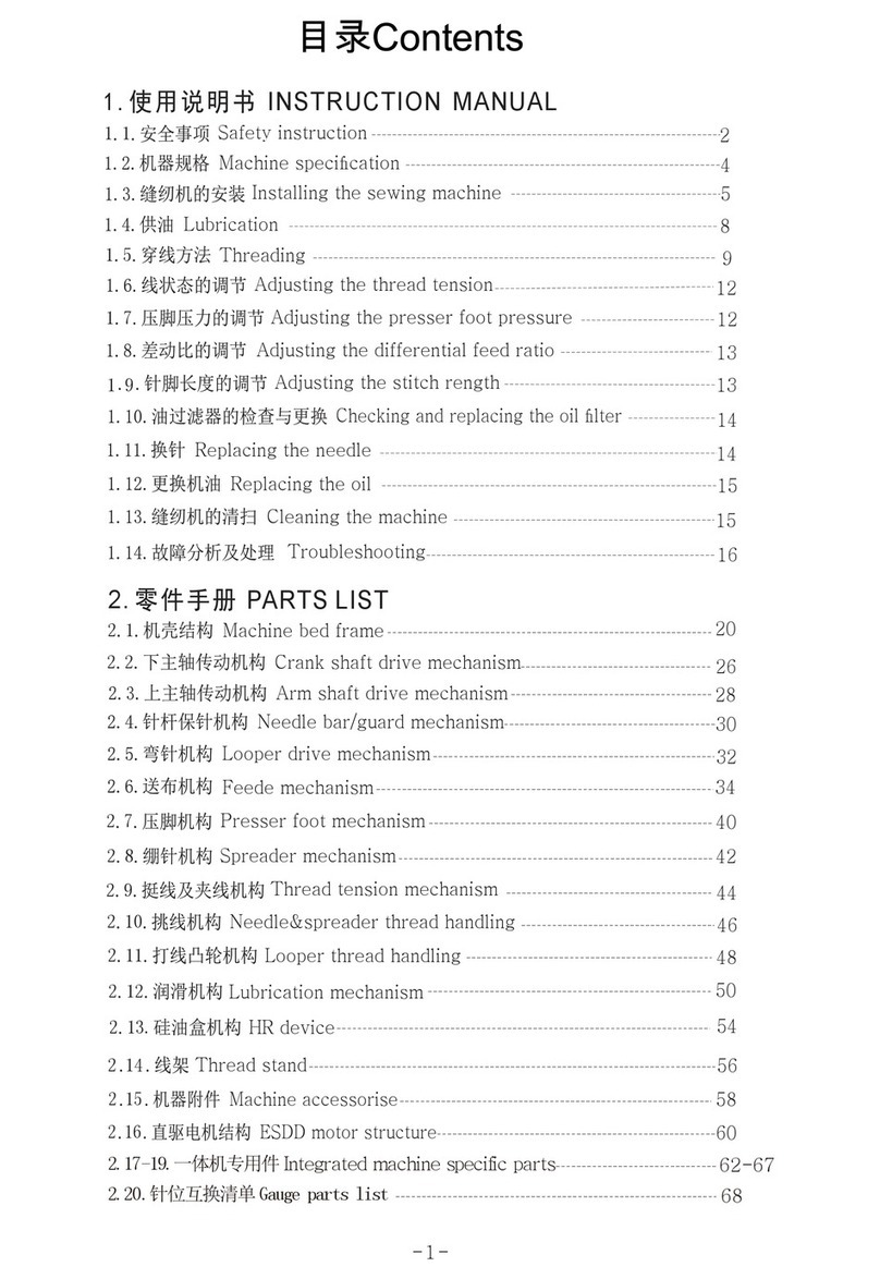
SAFETY INSTRUCTION -------------------------------------------------------------------------------1
一:PRODUCT INTRODUCTION --------------------------------------------------------------------------1
1 OVERVIEW
2 COMPONET
3 PERFORMANCE AND PARAMETER
4 APPLICATION
二:INSTALLATION AND ADJUSTMENT OF PENSILE-TYPE-------------------------------------3
1 INSTALLATION OF SYNCHRO
2 INSTALLATIONOFMOTOR
3 INSTALLATION OF CONTROL BOX
4 INSTALLATION OF PEDAL
5 CONNECTION OF SYSTEM
6 ADJUSTMENT
三:INSTALLATION AND ADJUSTMENT OF DIRECT-DRIVE TYPE ---------------------------7
1 INSTALLATIONOFMOTOR
2 INSTALLATION OF CONTROL BOX
3 INSTALLATION OF PEDAL
4 CONNECTION OF SYSTEM
5 ADJUSTMENT
四:OPERATION INSTRUCTION OF CONTROLPANEL------------------------------------------11
五:OPERATIONAL REQUIREMENTS -----------------------------------------------------------------13
六:MANTAINANCE AND GENERAL RECOVERY PROCESSING -----------------------------13
七:SETTING OF CONTROL BOX -----------------------------------------------------------------------15

1
CAUTION :
Please read instruction manual and completing instruction manual carefully before operation.
The Installation and operation must be operated under professional trained staff.
SAFETY INSTRUCTION:
1: Please read this manual carefully before installation and adjustment.
2: Installation and operation must be operated under professional trained staff.
3: Confirm the power connected to the ground safety and keep in accordance with the voltage range and
technical requirements in the nameplate.
4: Please leave your feet away from the padel when power is turned on or off.
5: You must cut the power off under operation metioned below:
A;install the machine
B;insert or pull out any plug in the control box
C;threading, changing needle and rotate the machine head.
D;machine maintainance and machine is in idle state.
6: The setting of control systemn and maintainance should be operated by trained staff.
7: There should be 5 seconds separate during changes of power
8: The system must be connected to the ground safety
一. PRODUCT INTRODUCTION
1. OVERVIEW
Energy-saving, cost-reducing and eviroment protecting is the core mission of 21th century.
The JK-500/600/700 control system extensively apply for industrial sewing machine and apparel
industry. This systme has the advantages of energy saving, high efficiency, stable performance and
reasonable price which win a good reputation since the system being launched. This system is the
best replace for clutch motor which used widely in industrial sewing machine.
2. COMPONENT
The system is made us of controller and motor.
A; Controller: The controller is made us of speed governor and control box (as picture 1)
1

2
The chip of this controller apply the newest AVR SCM of ATMEL LIMITED,
which can control the motor accurately with optimization algorithm. The power driver
of motor apply power intelligentize driver module of Fairchild Semiconductor. This
module has perfect performance on the protection to overvoltage, overcurrent and
overheating. The struction of controller is perfect and efficient. Padel-driven speed
governor is a part of motor speed controllor.
B; MOTOR
This motor apply mageneto AC motor structure, the rotor is made of
permanent-magnet material which has the advantages of small volume, high power,
energy saving, enviroment protecting and reliable. There is hall position sensor built
within the motor.
The product have mounted type (as picture 2 ) and direct-drive type (as picture 3 )
2 3
Accessories selection: Positioner, also called synchro and detector(as picture 4 showed),
which has a function of provding signal to the controller for needle position. It suits for the
type with function of needle position.
4

3
3 . PERFORMANCE AND PARAMETER
PERFORMANCE AND PARAMETER FOR JK-500/600/700 MAGNETO SERVO SYSTEM
controller model JK-500/600/700
model Energy-saving Servo Motor
power voltage range AC 220±10﹪V 50HZ
motoroutput 380W/550W
speed setting 4000rpm(pensile-type), 6000rpm(direct-drive type)
max speed 5000rpm(pensile-typ), 7000rpm(direct-drive type)
Maximum torque 380W /1N/M 550W / 1.5 N/M
needleup/down Optional(synchronizedneeded)
transistorprotection yes
package Twosetsinonecarton
grossweight 13KG
packing dimension 550×350×260
4. APPLICATION
A; 380W Motor is applicable to ordinary lockstitch sewing machine, overlock sewing machine
and those machines load light.
B; 550W motor is applicable to ordinary heavy duty lockstitch sewing machine, double needle
lockstitch sewing machine , heavy duty overlock sewing machine and interlock sewing
machine.
C; The customers should select proper power accroding to the concrete condition.
The electric power must be cut off in case of installation or dismantlement
二. INSTALLATION AND ADJUSTMENT OF PENSILE TYPE SYSTEM
1. Installation of synchro (non-positioning type can ignore this step) (as picture 5)
5
A:Pull down the driver of machine head, and set the synchro into the mounting hole which being
made beforehand (as picture 6 and 7)

4
6 7
B:Set the alnico in the fix position of driver according to the color mark, regard the first
positioning screw of main shaft as fiducial (counter-clockwise).(as picture 8)
910 8
C:Installation of driver. To adjust the position of drive in main shaft, and make the distance
between alnico and synchro is 2-3mm. To rotate the driver back and forth in order to
make sure the drive could rotate without friction. (as picture 9 and 10)
2. Installation of motor module (as picture 11)
a;Set three lifting screws into the foreseen hole in the table of sewing machine, and
fix the motor to the table. Adjust the postion of motor rack and make the motor
belt puller in the same lever with hand wheel and belt of sewing machine.
b;Adjustment of elasticity: press the belt with a force of one kg. It is ok if the belt
concave-down one centimeters, if not, the belt need adjustment. Install the belt
cover back.
The right make is the
installatioin position of
upper needle position

5
11
3. Installation of control box
Cutting two holes of one centimeters deep with a 3 drill∮in the right front of bottom
table, the distance between them is 195mm, and then fix the control box tightly with
wooden screw. Insert the plug of motor, synchro and speed controller into relevant socke,
and then fix the packed cable conductor to the table which far away from belt. (as picture
12 and 13)
12 13
4. Installation of padel (as picture 14 and 15)
Make sure the tention rod be perpendicular to the pedal. Adjust the angel of
tention rod, keep the filter angel to the ground lever as 15 degree.

6
14 15
5. Connection of system (as picture 16)
Connect controller power supply wire into singal phase 220V power supply
system, which should have seperately earthing device, and the control box must
be connect to earth safely. Insert the plug of motor, speed controller and synchro
into the socket behind the control box. When everything is ready, check if the
connection stable again, and then adjust the position of plastic sheath in order to
cover the plugs totally.
16
Connector defination behind of the control box

7
6.Adjustment
Adjustment of needle position (non-positioning type can ignore this step)
Connect to the power, and turn up the mains switch of control box. Rotate the
driver of sewing machine, when it stop at the up needle position, lighten the
red luminotron in the synchro, adjust the position of alnico which have red
mark, and then fix the screw. In a similar way, Rotate the driver of sewing
machine, when it stop at the lower needle position, adjust the position of
alnico which have blue mark, lighten the green luminotron in the synchro
and then fix the screw.
三. INSTALLATION AND ADJUSTMENT OF DIRECT-DRIVE TYPE
Uninstallthehandwheelasbelowed:
1. decompose the direct-drive motor, break it into forth and back cover, rotor, and stator. (as
picture 17)
17 18

8
2. Make the main shaft cross the forth cover and keep it in the same lever which is
perpendicular to the main shaft, and then fix the screw. (as picture 18)
3. Find the position of main shaft flat, make the flat towards up, then cover it to the end with
rotor of motor, then positioning the screw in rotor shaft to the flat of main shaft and fix it. (as
picture 19)
4. Install the stator to the fixed forward cover of motor (the rotor of motor have strong
magnetism, so please be caution on operation in order to avoid hurt finger and demage the
motor. Please keep caution to the position and direction of down-lead wire of stator before
installation. The position of down-lead wire of stator is under the forward cover.) (as picture
20)
19 20
5. after the installation of stator, it needs to check the distance between stator and
rotor. The standart distance should be 0.5mm per circle. There should be no any
metal materials to be sucked in the distance. (as picture 21)
6. Piece on the forward and backward cover of motor, fix the screw. (as picture 22)
21 22
7. There is blue marked alnico installed near to the second fixing screw (counter-clockwise) ,
and on the other alnico installation position should be red marked alinco.
8. Cover the motor shaft with hand wheel, and towards flat in the motor with first screw in the
hand wheel then fix the screw. Please keep caution to the distance between alnico and sensor
flat during installation, 2-3mm is proper. There should be no friction when rotating the hand
wheel.(as picture 23and 24)

9
23 24
9.Installation of control box
Cutting two holes of one centimeters deep with a 3 drill in the right front of bott∮om
table, the distance between them is 195mm, and then fix the control box tightly with
wooden screw. Insert the plug of motor, synchro and speed controller into relevant
socke, and then fix the packed cable conductor to the table which far away from belt.
(as picture 25 and 26)
25 26
10.Make sure the tention rod be perpendicular to the pedal. Adjust the angel of
tention rod, keep the filter angel to the ground lever as 15 degree.(as picture
27 and 28)

10
27 28
11. Connection of system
Connect controller power supply wire into singal phase 220V power supply
system, which should have seperately earthing device, and the control box must
be connect to earth safely. Insert the plug of motor, speed controller and synchro
into the socket behind the control box. When everything is ready, check if the
connection stable again, and then adjust the position of plastic sheath in order to
cover the plugs totally.
29
Connector defination behind of the control box (as picture 29)

11
12. Adjustment of needle position (non-positioning type can ignore this step)
Connecting to the power, and turning up the mains switch of control box.
Rotate the driver of sewing machine, when it stop at the up needle position,
lighten the red luminotron in the synchro, adjust the position of alnico which
have red mark, and then fix the screw. In a similar way, Rotate the driver of
sewing machine, when it stop at the lower needle position, adjust the position
of alnico which have blue mark, lighten the green luminotron in the synchro
and then fix the screw.
四. OPERATION INSTRUCTION OF CONTROLPANEL

12
1. WPS, the nixietube shows P
图32
2. Press P, the nixietube shows V which is the speed setting interface.
Then press S, you can adjust the speed from 1-9 which increase in a circle, the
matching speed limitation from 500 to 4500 R/S (the concrete speed depend on
the machine type)
3. Press Pagain, function b is the rotating direction setting interface,

13
Press S: It will be corotation when the nixietube shows 0 (the model is suitable for
lockstitch sewing machine, and the point below the number will be lighten)
It will be inversion when the nixietube shows 1 (the model is suitable for
overlock sewing machine, and the point below the number will go out)
4. Conservation of date
When all the parameter is setting ready, press P, the nixietube will show O and
K seperately when date is stored sucessfully, on the contrary, Er means the
store failed. If the data cannot be stored, please turn the controller down, and
then turn it up in a while. Re-operate from 1-4
5. System recovery function:
When the controller cannot work regularly, press S on the P interface till the
nixietube shows O and K which could recover the system parameter to the leave
factory setting.
五OPERATIONAL REQUIREMENTS
1; Please keep this system away from high magnetic fields and environmental
radiation in order to avoid obstructions.
2;The operational temperature must be in the range of 5℃--45℃
3;Please don’t use this product near to the origin of heat (heat, radiator)
4;Please don’t use this product in overwet circumstances.
5;Please don’t use this product near to corrosive liquids and explosion..
6;Keep ventilation to where the controller and motor stored.
7;Keep the power supply voltage steady.
8;There must be qualified connector to the ground in order to make sure safety.
六.MANTAINANCE AND GENERAL RECOVERY PROCESSING
If the machine went wrong, maintainance and repairment should be operated
under professional trained person.

14
1. No reaction when the controller is turning up
34
Please check if the power plug connected to the socket tightly, or if the
protective tube is burnt, if yes, change the protective tube. Open the cover of
controller first, find the position of protective tube, take the burnt protective
tube out and change a new one. The model of protective tube is 5A/250V
¢5mm×20mm
2. Controller is connected, but the motor doesn’t work when pressing the padel.
Please check if the plug of speed adjustor, motor and motor signal wire is
connected to the socket in controller right. Check if the speed adjustor is broken.
3. The rotate speed of motor sometimes fast and sometimes slow
Please check if the belt is too loose, and if the belt puller slipped, or the padel and
tension rod is loose.
4. The motor stopped duiring running
Please check if the machine load too heavy first or there is mechanical bug. Then
check is the power socket and plug connected to the motor hall socket and plugs
well. The same to the socket and plug of speed adjustor.
5. The motor will run without stop when the controller is turning on.
A; Check if the working model is setting at 0, if setting at other model without
installation of synchro, the motor will run without stop.
B; Please check if the position of alnico within speed adjustor changed. The
method is as belowed mentioned:
Open the plastic cover of speed adjustor, loose the fixed screw. Then adjust the
position of swinging arm (picture 35 is the position oof swinging arm when
working), make the alnico within swinging arm on the right up of hall,
generally, the machine could stop. If not, adjust the position again by
clockwise.

15
35 36
6. Nixietube alternate displays E1
This condition shows the motor has operational failure, please check if the
sewing material is too heavy or the machine needs lubrication.
7. Nixietube alternate displays E2
This condition shows the motor is overcurrent or undervoltage, please check if
the power supply voltage is normal, the normal poer supply voltage should be
from 200V and 240V.
8. Nixietube alternate displays E3
You need to cut off the power and then turn it on again.
9. If the protective tube is burnt on boot-start, and the error still exist when
change a new protective tube, please contact to distributor locally.
10. If there is any other error which not included above, please contact with
distributor locally.
七.SETTING OF CONTROL BOX
•P is the user setting interface, F is the facotry setting interface.
•The way to cut over from P to F: Press botton F first, and then press P together
with F, when the liquid cristal box shows F which means factory setting
interface.
•There are two parameters under P interface.
–V shows speed setting, from 0-9.
–B show running direction setting, 0 means clockwise running, 1 means
inverse hours running.
•There are seven parameters under interface F.
–M is working model setting, 0 means ordinary, 1 means upper and
lower needle positioning, 2 mean upper needle positioning.
–L is speed limitation setting, from 0-9.
–C is working current setting, from 0-9
–N is start speed setting, from 0-9
–U is the upper needle positioning setting, from 0-9

16
–D is the lower needle positioning setting, from 0-9
–A can store current parameter as windows default, press F, it will be
suceed when show OK in the interface, if not, it will shows Er.
•Press P to store the setting finally.
Thanks for your using of the product of ZHEJIANG NEW JACK SEWING MACHINE CO.,
LTD, please let us know your opinion and suggestion to our product in order to get better service
from us.
ZHEJIANG NEW JACK SEWING MACHINE CO., LTD
Telephone for after-sales service
800-8576858
This manual suits for next models
2
Table of contents
