Pfaff 1181 Guide

This Adjustment Manual is valid for machines from the
following serial numbers onwards:
# 6001000
Adjustment Manual
118 1
118 3
296-12-18 710/002
Justieranleitung engl. 06.04
1181-D
1183-D

The reprinting, copying or translation of PFAFF Service Manuals, whether in whole or in part,
is only permitted with our previous authorization and with written reference to the source.
PFAFF Industrie Maschinen AG
Postfach 3020
D-67653 Kaiserslautern
Königstr. 154
D-67655 Kaiserslautern

Contents
Contents ...............................................................................Chapter - Page
13 Adjustment ............................................................................................................. 13 - 1
13.01 Tools, gauges and other accessories for adjusting................................................... 13 - 1
13.02 Abbreviations ........................................................................................................... 13 - 1
13.03 Explanation of the symbols ...................................................................................... 13 - 1
13.04 Checking and adjusting aids ..................................................................................... 13 - 2
13.05 Adjusting the basic machine .................................................................................... 13 - 3
13.05.01 Basic position of the machine drive ......................................................................... 13 - 3
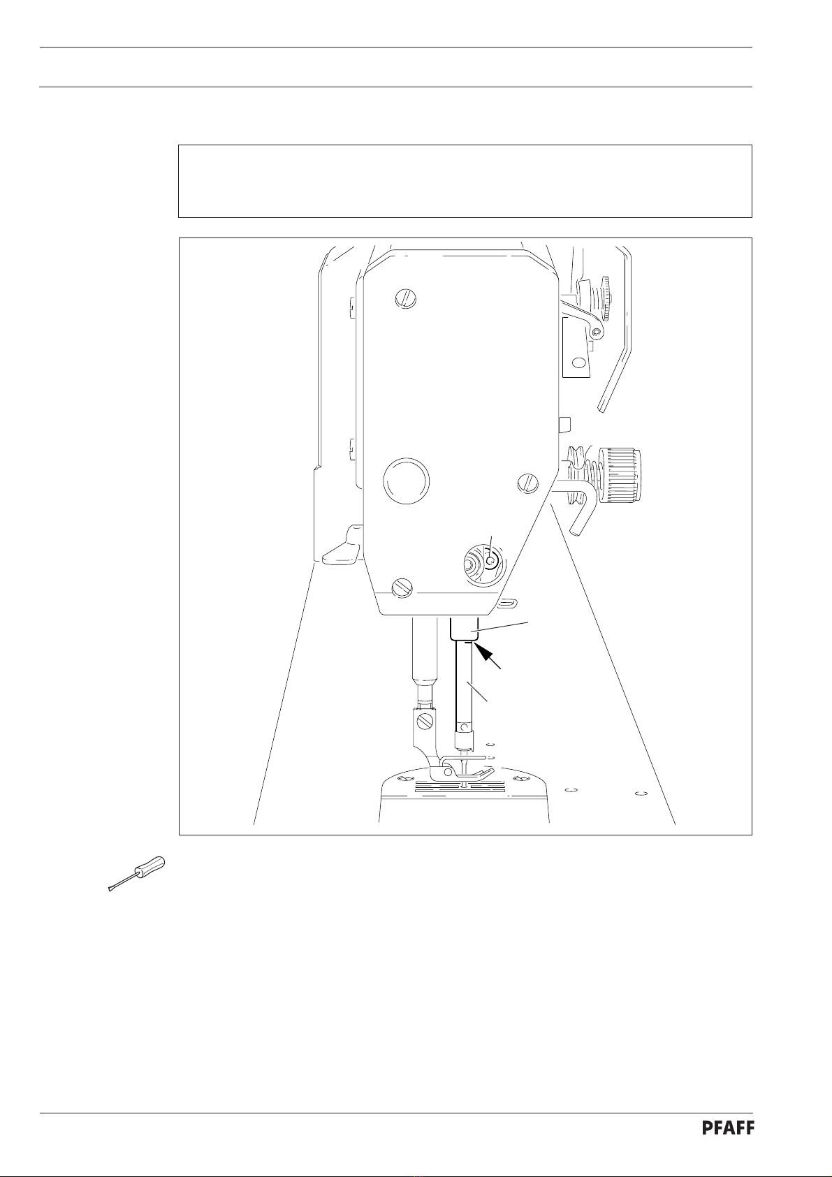
13.05.02 Preadjusting the needle height................................................................................. 13 - 4
13.05.03 Bottom feed neutral position.................................................................................... 13 - 5
13.05.04 Neutral position of the needle feed (only on PFAFF 1181) ....................................... 13 - 6
13.05.05 Bottom feed lifting motion ....................................................................................... 13 - 7
13.05.06 Bottom feed dog height ........................................................................................... 13 - 8
13.05.07 Feed dog motion of bottom feed dog ...................................................................... 13 - 9
13.05.08 Feeding motion of needle feed (only on PFAFF 1181).............................................. 13 - 10
13.05.09 Needle in needle hole center (only on PFAFF 1183) ................................................. 13 - 11
13.05.10 Needle to needle hole centre (on PFAFF 1181) ........................................................ 13 -12
13.05.11 Synchronous strokes of needle- and drop feed (only on PFAFF 1181) ..................... 13 - 13
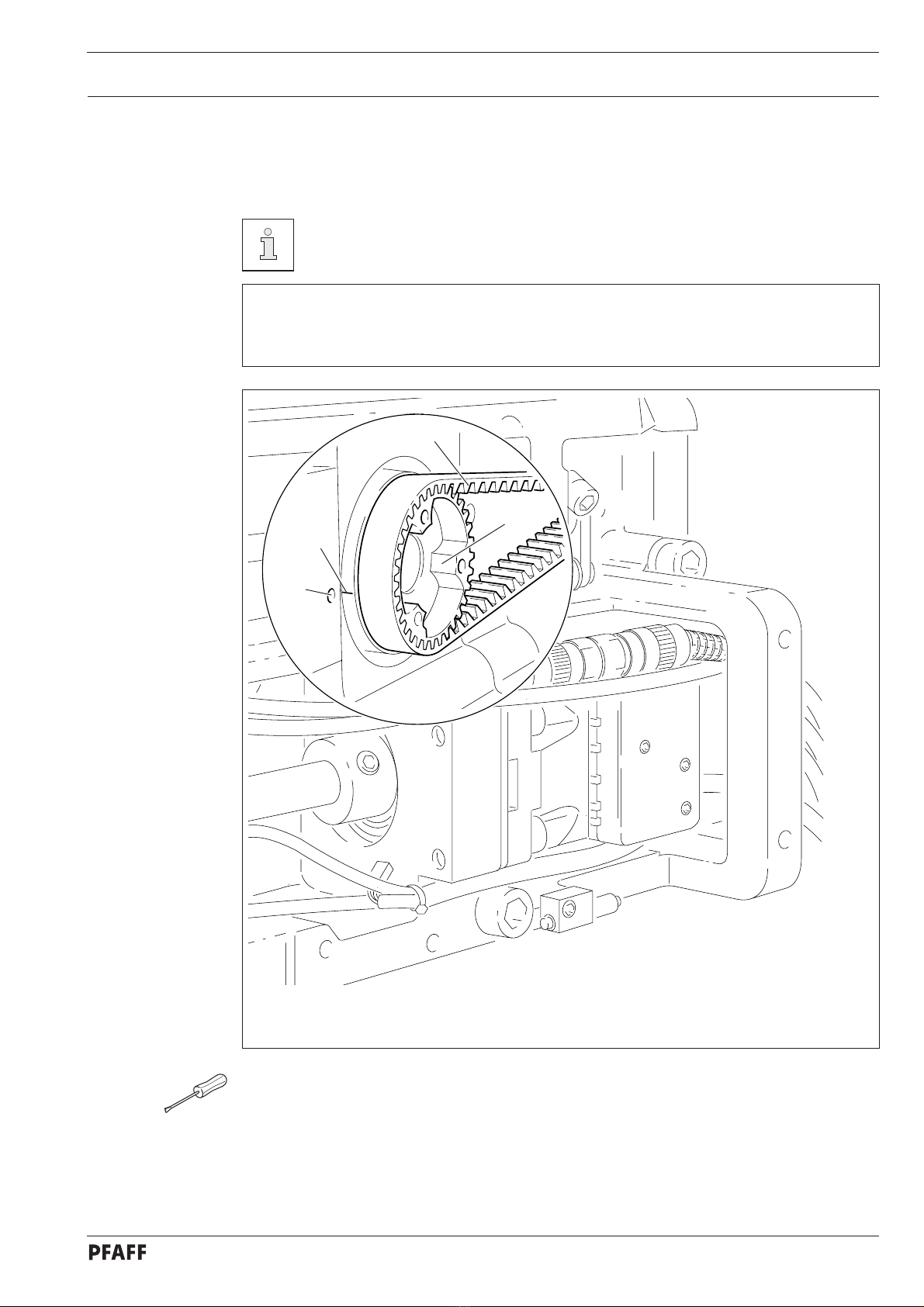
13.05.12 Hook shaft bearing and toothed belt tension ........................................................... 13 -14
13.05.13 Hook lubrication ....................................................................................................... 13 -15
13.05.14 Needle rise, hook-to-needle clearance, needle height and bobbin case position finger 13 - 16
13.05.15 Thread check spring and slack thread regulator ....................................................... 13 -17
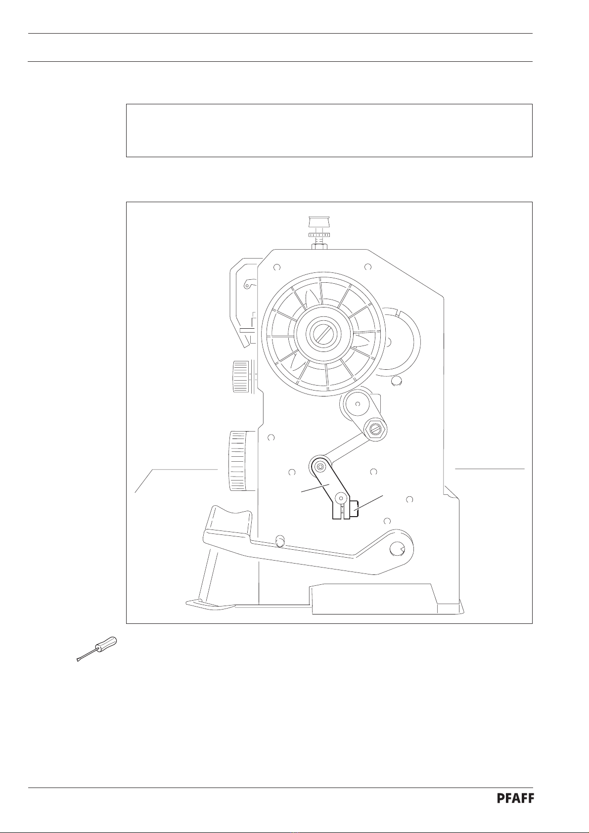
13.05.16 Position of knee lever............................................................................................... 13 - 18
13.05.17 Knee lever stop ........................................................................................................ 13 -19
13.05.18 Bobbin winder .......................................................................................................... 13 - 20
13.05.19 Limiting the stitch length.......................................................................................... 13 - 21
13.05.20 Stitch length adaptation ........................................................................................... 13 - 22
13.05.21 Presser foot pressure .............................................................................................. 13 -23
13.05.22 Modifying the needle bar stroke .............................................................................. 13 - 24
13.06 Adjusting the edge trimmer –731/01........................................................................ 13 - 25
13.06.01 Zero position of the knife ......................................................................................... 13 - 25
13.06.02 Cutting motion ......................................................................................................... 13 - 26
13.06.03 Knife height.............................................................................................................. 13 -27
13.06.04 Knife position in sewing direction............................................................................. 13 - 28
13.06.05 Knife position crosswise to sewing direction ........................................................... 13 - 29
13.07 Adjusting the thread trimming device -900/24.......................................................... 13 - 30
13.0.01 Adjusting the solenoid / preliminary adjustment of the control cam......................... 13 -30
13.07.02 Lateral alignment of the thread catcher ................................................................... 13 -31
13.07.03 Knife position ........................................................................................................... 13-32
13.07.04 Front point of reversal of the thread catcher ............................................................ 13 - 33
13.07.05 Manual trimming check............................................................................................ 13 - 34

Contents
Contents ...............................................................................Chapter - Page
13.07.06 Needle thread tension release ................................................................................. 13 - 35
13.07.07 Readjusting the control cam .................................................................................... 13 - 36
13.08 Adjusting the thread wiper -909/04 .......................................................................... 13 - 37
13.08.01 Thread wiper movement.......................................................................................... 13 - 37
13.08.02 Thread wiper position............................................................................................... 13 -38
13.09 Adjusting the automatic presser foot lift -910/06 ..................................................... 13 - 39
13.10 Adjusting the back-tacking mechanism –911/37 ...................................................... 13 - 40
13.11 Parameter settings................................................................................................... 13 - 41
13.11.01 Selecting the user level............................................................................................ 13 - 41
13.11.02 Example of a parameter input .................................................................................. 13 - 42
13.11.03 Liste der Parameter ................................................................................................. 13 - 43
13.11.04 Reset / Cold start ..................................................................................................... 13 - 44
13.12 Internet update of the machine software................................................................. 13 - 45
13.13 Explanation of the error signals ................................................................................ 13 - 46
14 Circuit diagrams ..................................................................................................... 14 - 1

Adjustment
13 - 1
13 Adjustment
On the PFAFF 1181 and 1183 do not use a screw clamp on the needle bar! The
special coating of the needle bar could be damaged.
Please observe all notes from Chapter 1 Safety of the instruction manual! In
particular care must be taken to see that all protective devices are refitted
properly after adjustment, see Chapter 1.06 Danger warnings of the
instruction manual!
If not otherwise stated, the machine must be disconnected from the electrical
power supply.
All following adjustments are based on a fully assembled machine and may only be carried
out by expert staff trained for this purpose.
Machine covers, which have to be removed and replaced to carry out checks and
adjustments, are not mentioned in the text.
The order of the following chapters corresponds to the most logical work sequence for
machines which have to be completely adjusted. If only specific individual work steps are
carried out, both the preceding and following chapters must be observed.
Screws, nuts indicated in brackets ( ) are fastenings for machine parts, which must be
loosened before adjustment and tightened again afterwards.
13.01 Tools, gauges and other accessories for adjusting
●1 set of screwdrivers with blade widths from 2 to 10 mm
●1 set of wrenches with jaw widths from 7 to 14 mm
●1 set of Allan keys from 1.5 to 6 mm
●1 metal rule, (Part No. 08-880 218-00)
●1 feed dog adjustment gauge, Part No. 61-111 639-71
●1 adjustment pin (5 mm dia.), Part No. 13-033 346-05
●Adjustment gauge, part No. 61-111 639-70
●1 adjustment gauge for tightening the hook drive belt, Part-No. 61-111 639-76
●Sewing thread and test material
13.02 Abbreviations
TDC = top dead center
BDC = bottom dead center
13.03 Explanation of the symbols
In this adjustment manual, symbols emphasize operations to be carried out or important
information. The symbols used have the following meaning:
Note, information
Service, repair, adjustment, maintenance
(work to be carried out by qualified staff only)

Adjustment
13 - 2
13.04 Checking and adjusting aids
With the aid of blocking pin 1(part No. 13-033346-05) and if necessary
adjustment gauge 3(part No. 61-111 639-70) the machine can be blocked in the
following positions for adjustment
Fig. 13 - 01
1
2
4
5
3
Needle bar position 1.8 mm past b.d.c.
●Turn balance wheel until needle bar is roughly in required position
●Insert blocking pin 1in hole
●Turn balance wheel slightly back and forth until blocking pin engages crank 2
Needle bar position 0.6 mm past t.d.c.
●Set needle bar roughly at required position
●Place adjustment gauge 3onto pins 4and 5, making sure right side is used (for 30 or 36
mm needle bar stroke)
Needle bar position 0.6 mm past b.d.c.
●Set needle bar roughly at required position
●Place adjustment gauge 3onto pins 4and 5, making sure right side is used (for 30 or 36
mm needle bar stroke)

Adjustment
13 - 3
13.05 Adjusting the basic machine
13.05.01 Basic position of the machine drive
This adjustment is only required if toothed belt 2has been removed.
Requirement
When the needle bar position is 0.6 mm above the BDC, the marks on the machine
housing 3and toothed belt wheel 1must be flush with each other.
●Set needle bar at 0.6 mm past b.d.c.
●Turn toothed belt sprocket 1according to Requirement and push on toothed belt 2.
Fig. 13 - 02
57-42a
3
4
1
2

Adjustment
13 - 4
13.05.02 Preadjusting the needle height
Requirement
When the needle bar is positioned 1.8 mm above BDC, the mark on the needle bar 1must
be flush with the bottom edge of the needle bar frame 3.
Fig. 13 - 03
●Set needle bar at 1.8 mm past b.d.c. and block machine with blocking pin, see
Chapter 13.04 Checking and adjusting aids.
●Move needle bar 1(screw 2), without turning it, according to the requirement.
2
1
3

Adjustment
13 - 5
13.05.03 Bottom feed neutral position
Requirement
At stitch length setting "0", cranks 1and 3must be flush and the feed dog must not make
any feeding motion when the balance wheel is turned.
●Raise the presser foot and set the stitch length to "0".
●Turn crank 1(screw 2) according to the requirement.
Fig. 13 - 04
31
2

Adjustment
13 - 6
13.05.04 Neutral position of the needle feed (only on PFAFF 1181)
Requirement
At stitch length setting "0"the needle bar must not make any feeding motion when the
balance wheel is turned.
●Set stitch length "0".
●Turn crank 1(screw 2) according to Requirement.
Fig. 13 - 05
12

Adjustment
13 - 7
13.05.05 Bottom feed lifting motion
Requirement
At stitch length setting "0"and needle bar position 0.6 past b.d.c. on the PFAFF 1181 and
at needle bar position t.d.c. on the PFAFF 1183,
1. the bottom feed dog must be at its highest position,
2. control cam 3 must rest on lifting eccentric 1.
●Set stitch length "0"and set needle bar at required position
●Turn eccentric 1(screws 2) according to Requirement 1.
●Adjust control cam 3(screws 4) according to Requirement 2.
Fig. 13 - 06
4
1
3
2

Adjustment
13 - 8
13.05.06 Bottom feed dog height
Requirement
When feed dog 1 is at its highest point at stitch length setting "0"it must
1. be centred in the feed slot crosswise and in feeding direction
2. Rest on feed dog adjustment gauge 2 over its entire length.
●Set stitch length at "0"and feed dog 1at its highest position
●Raise the presser foot.
●Place feed dog adjustment gauge 2on the needle plate cutout with the arrow in sewing
direction so that it is flush with the front edge, and lower the presser foot onto it.
●Adjust feed bar 3(screws 4) according to Requirement 1.
●Loosen screws 5and 6.
●Adjust feed bar 3or eccentric 7according to Requirement 2.
●Tighten screws 5and 6firmly.
4
6
7
3
5
Fig. 13 - 07
57-34
2
1

Adjustment
13 - 9
13.05.07 Feed dog motion of bottom feed dog
Requirement
With the needle bar at a position 0.6 past b.d.c. on the PFAFF 1181 or in position 0.6 past
t.d.c. on the PFAFF 1183 the feed dog must not make any feeding motion when reverse-
feed lever 3is operated at the longest stitch length setting.
●Set the longest stitch and the needle bar at the corresponding position.
●Adjust eccentric 1(loosen screws 2a little) according to Requirement, but make sure it is
not moved sideways.
Fig. 13 - 08
3
1
2

Adjustment
13 - 10
Fig. 13 - 09
1
2
3
3
●Bring the needle bar into the position 0.6 mm past t.d.c.
●Turn eccentric 1(screws 2) until the adjustment pin 3locks into place.
13.05.08 Feeding motion of needle feed (only on PFAFF 1181)
Requirement
When the longest stitch length is set and the needle bar is positioned 0.6 mm past b.d.c.,
the needle should not move when the reverse-feed key 4is operated.

Adjustment
13 - 11
13.05.09 Needle in needle hole center (only on PFAFF 1183)
Requirement
The needle must penetrate the needle hole exactly in the middle.
●Set the needle in the needle hole.
●Loosen screws 1, 2 and 3.
●Move the needle bar frame 4according to the requirement.
●Tighten screw 2and turn screw 3slightly.
●Via screw 1, bring the retracted guide bolt to the eye of the needle bar frame 4and
tighten it.
●Turn the handwheel a few times to prevent distortion to the needle bar frame 4.
●Tighten screw 3.
1
4
Fig. 13 - 10
3
2

Adjustment
13 - 12
13.05.10 Needle to needle hole centre (on PFAFF 1181)
Requirement
The needle must enter excatly in the centre of the needle hole.
●Set stitch length "0".
●Set the needle in the needle hole by turning the balance wheel
●Turn needle bar frame 1(screws 2and 3) according to Requirement.
Fig. 13 - 11
1
3
2

Adjustment
13 - 13
13.05.11 Synchronous strokes of needle- and drop feed (only on PFAFF 1181)
Requirement
At the longest stitch length setting the needle and feed dog must move by the same
stroke when the balance wheel is turned.
●Set the longest stitch.
●Turn eccentric 1(nut 2) according to Requirement .
Fig. 13 - 12
2
1

Adjustment
13 - 14
13.05.12 Hook shaft bearing and toothed belt tension
Requirement
1. The front edge of the hook shaft 6must be at a distance of 14.5 mm to the needle
center. At the same time, the slot in the hook shaft bearing 1(see arrow) must be paral-
lel to the bedplate and pointing opposite to the direction of sewing.
2. The toothed belt should be tightened in such a way that, when the gauge is pushed
onto the toothed belt, the marking in the gauge window corresponds to the marking on
the bushing.
●Align hook shaft bearing 1(screw 2) according to requirement 1.
●Push the gauge (Part-No. 61-111 639-76) onto the toothed belt so that it is centred to the
toothed belt and touching the bearing of the sliding shaft. The gauge window must be
facing the hook.
●Eccentric 3(screw 4) clockwise in accordance with requirement 2, taking care that the
axial position of eccentric 3is not altered.
1
3
Fig. 13 - 13
4
1
5
2
14,5 mm

Adjustment
13 - 15
The adjustment is only necessary if the wick has been replaced.
When replacing the wick, make sure that the new wick is impregnated with oil.
●Move the centrifugal disk 1(screw 2) according to requirement 1.
●Check requirement 2. If necessary, move centrifugal disk 1.
13.05.13 Hook lubrication
Requirement
1. The centrifugal disk 1must be positioned 1.5 mm in front of the oil ring 3.
2. When the machine is running at full speed, after approx. 10 seconds a mark should be
made by a fine stripe of oil on the strip of paper placed over the needle plate cutout.
Fig. 13 - 14
2
1
3
1,5 mm

Adjustment
13 - 16
13.05.14 Needle rise, hook-to-needle clearance, needle height and bobbin case position finger
Requirement
With the needle at 1.8 mm after BDC,
1. the hook point 6must point to the middle of the needle and be at a distance of
0.05 mm - 0.1 mm to the clearance cut of the needle, and
2. the top edge of the needle eye must be 0.8 mm below the hook point.
3. Between the projection of the bobbin case position finger 4and the bottom of the
retaining groove there should be a distance of 0.5 mm.
●Using the adjustment pin, position the needle bar at 1.8 mm after BDC.
●Adjust the hook according to requirement 1.
●Tighten screw 1.
●Move needle bar 2(screw 3) without turning it according to requirement 2.
●Align bobbin case position finger 4(screw 5) according to requirement 3.
Fig. 13 - 15
0.05 - 0.1 mm
6
10.5 mm
4
5
4
2
3
0.8 mm
Other manuals for 1181
4
This manual suits for next models
3
Table of contents
Other Pfaff Sewing Machine manuals

Pfaff
Pfaff 1245 User manual

Pfaff
Pfaff Automatic 260 User manual

Pfaff
Pfaff admire 1000 User manual

Pfaff
Pfaff Creative Performance User manual

Pfaff
Pfaff 333-712/02 User manual

Pfaff
Pfaff creative 2170 Guide

Pfaff
Pfaff ambition 1.0 User manual

Pfaff
Pfaff 3566-2/02 User manual

Pfaff
Pfaff 238 User manual

Pfaff
Pfaff 1070s User manual