New lift Pam-E4 User manual

GATEWAY ELEVISION 4.0
MANUAL

PAM.E4 manual
Manufacturer NEW LIFT
Neue elektronische Wege
Steuerungsbau GmbH
Lochhamer Schlag 8
82166 Gräfelng
Phone +49 89 – 898 66 – 0
Fax +49 89 – 898 66 – 300
E-mail [email protected]
www.newlift.de
Service line Phone +49 89 – 898 66 – 110
E-mail [email protected]
First edition 15/07/2020
Author ASC / DOS
Last change 26.08.2020 AME
Release 26.08.2020 TF
Software version PAM.E4 V1.6.1604
Doc. no. hb_PAM-E4_2020-07_V1.5_en
Copyright © NEW LIFT Steuerungsbau GmbH, 2020.
This manual is protected by copyright. All rights, including those of copying,
of reproduction, of translation and of modication, in whole or in part, are
reserved by the publisher.
No part of this description may be reproduced in any form or copied with an
electronic replication system without written permission.
Although great care has been taken in the production of texts and gures, we
cannot be held legally liable for possible mistakes and their consequences.

PAM.E4 manual 3
Contents
1 General 5
1.1 Functional description 5
1.2 Abbreviations, characters and symbols used 5
1.3 Notation 5
1.4 Further information 6
1.5 How to contact us 6
2 Safety 7
2.1 Handling electronic assemblies 7
2.2 Residual dangers and protective measures 7
3 Technical data 8
3.1 Overview 8
3.2 Technical data 9
4 Installation 10
4.1 Delivery contents 10
4.2 Overview of connection options 11
4.3 Controller side – Connecting PAM.E4 to FST 12
4.4 Server side – Connection to ELEVISION 4 13
4.4.1 Ethernet / Ethernet 13
4.4.2 RS232 / modem 13
4.4.3 RS232 or Ethernet / LTE 14
4.5 Connecting mains supply line (Power) 15
4.6 Checking status of connection 15
5 Conguration 16
5.1 Login and logout 17
5.2 Menu structure 18
5.2.1 Main window 18
5.2.2 Menu and tabs 18
5.2.3 Buttons and slide controls 19
5.3 Status tab 20
5.3.1 Overview 20
5.3.2 Version 21
5.4 Gateway tab 22
5.4.1 Settings for connection to Elevision 4 / Connectivity 23
Interface Settings 24
Setting connection behaviour / Time Settings 25
Setting IP of Elevision 4.0 server / Elevision Server Settings 26
5.4.2 User preferences / User Settings 27
5.4.3 Conguration/CongFile 27
Import/export conguration 27

4PAM.E4 manual
5.5 Controller tab 28
5.5.1 Basic settings / Basic Setup 28
Lift / conguration of lift type and identication 29
Conguration of connection to controller / Interface Settings 29
5.5.2 Input and output settings / Input/Output 30
5.5.3 Shaft settings / Floor Plan – for third‑party controllers 30
5.5.4 Shaft settings / Lift Warden – for third‑party controllers 30
6 Events 31
6.1 List of events / Event List 31
6.2 Event assignments – FST controllers 34
7 FAQ 38
7.1 How do I commission a Base GSM13 in combination with the PAM.E4? 38
7.2 Why can't I set up a connection to the Elevision server? 39
7.3 Why can't I set up a connection to the controller? 39

General
PAM.E4 manual 5
1 General
1.1 Functional description
The PAM.E4 is used to connect the lift controller (NEWLIFT FST controller or a different controller) to
the Elevision4.0 web platform.
Using the PAM.E4
›the lift system can be monitored in real-time via the Elevision 4.0 system
›availability data can be collected and then provided for further evaluation
›the lift system can be checked by means of the lift attendant function in combination with Elevision4.0.
1.2 Abbreviations, characters and symbols used
Symbol /
abbreviation Meaning
MSB‑RC Installation drive pod
► Operational instructions
Perform the tasks that follow this symbol in the specied order.
• Action step under the respective operational instruction
Safety information
This symbol is located in front of safety-relevant information.
Information notice
This symbol is located in front of relevant information.
1.3 Notation
Notation Meaning
Bold ›Designations of switches and actuators
›Input values
Italics ›Captions
›Cross references
›Designations of functions and signals
›Product names
Bold italics ›Remarks
LCD font ›System messages of the controller

General
6PAM.E4 manual
1.4 Further information
The following documents, among others, are available for the FST controller and its components.
›FST-2XT/s manual
›GST-XT manual
›ELEVISION 4.0 manual
These and other current manuals can be found in the download area of our website at
https://www.newlift.de/downloads.html
1.5 How to contact us
If, after referring to this manual, you still require assistance, our service line is there for you:
Phone +49 89 – 898 66 – 110
E-mail [email protected]
Mon. - Thurs.: 8:00 a.m. – 12:00 p.m. and 1:00 p.m. – 5:00 p.m.
Fr: 8:00 a.m. – 3:00 p.m.
Safety
PAM.E4 manual 7
2 Safety
The PAM.E4 must only be operated in perfect working condition in a proper manner, safely and in com-
pliance with the instructions, the valid accident prevention regulations and the guidelines of the local
power company.
The safety guidelines of the FST manual and the FST Installation and Commissioning manual apply
for this product.
2.1 Handling electronic assemblies
Electrostatic charging
›Keep the electronic assembly in its original packaging until installation to prevent damage.
›Before opening the original packaging, a static discharge must be performed!
To do this, touch a grounded piece of metal.
›During work on electronic assemblies, periodically repeat this discharge procedure!
›Equip all bus inputs/outputs not in use with a terminal resistor (terminator) to prevent malfunctions.
2.2 Residual dangers and protective measures
Dangerous electrical voltage!
In its installed state, the PAM.E4 is connected to the 230VAC power supply.
Touching electrically live parts either directly or indirectly can result in an electric shock.
►Take particular care when carrying out all work.

Technical data
8PAM.E4 manual
3 Technical data
Software requirements
›PAM.E4 v1.6.1604
Hardware requirements
›PAM.E4 (GSR 140B)
At present, the PAM.E4 system can be used only in combination with FST controllers.
3.1 Overview
Front side
1 2 3 4 5 6 7
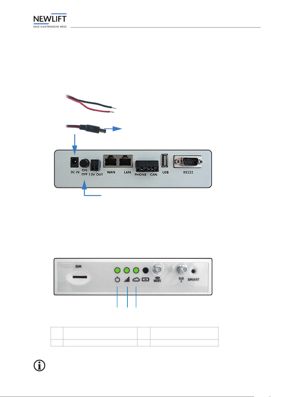
1 SIM card slot 5 LED – battery charge
level
2 LED – power ON 6 WiFi antenna port
3 LED – LTE connection present 7 LTE antenna port
4 LED – E4 cloud connection present
Rear side
Interface Function
DC IN Power supply
ON / OFF Power button
12 V OUT 12V / 1A output
WAN Connection to the Internet
LAN Connection to the control system
PHONE Telephone interface (not available)
CAN CAN interface (not available)
USB Not available
RS232 Connection to the controller / modem

Technical data
PAM.E4 manual 9
3.2 Technical data
Mechanical data Type PAM.E4 (standard version)
Dimensions without cable L x W x H = 177 x 90 x 45 mm
Weight Approx. 500 g
Cable length – serial cable
(null modem, 1:1)
Max. 2 m
Cable length – patch cable (cat5) Max. 100 m
Feed line length – LTE antenna 3 m
Ambient conditions Storage temperature -20°C…+65°C
Operating temperature -20°C…+65°C
EMC emitted interference / inter-
ference immunity
In compliance with (EMC)
2014/30/EU
RED (Radio Equipment Directive) 2014/53/EU
LVD (Low Voltage Directive) 2014/35/EU
Mobile network GSM / GPRS / EDGE bands 900 / 1800 MHz
WCDMA / HSDPA / HSPA+ bands B1 / B5 / B8
TDD-LTE bands B38 / B40 / B41
FDD-LTE bands B1 / B3 / B5 / B7 / B8 / B20
Wireless network
Electrical data
Wi support 150M 2.4 GHz WiFi, 802.11
b/g/n
12VDC output 1A
Lithium battery 2500 mAh
Avg. consumption 400 mA
Max. consumption 2A (18VDC)
Working range 12VDC - 24VDC

Installation
10 PAM.E4 manual
4 Installation
4.1 Delivery contents
›PAM.E4 gateway
›Power supply cable
›WLAN and LTE antenna
›Connection cables – Ethernet or RS232 cables
»Variant 1 – Ethernet / Ethernet: 2x Ethernet (patch cables, 2 m)
»Variant 2 – Ethernet / LTE: 1x Ethernet (patch cable, 2 m)
»Variant 3 – Ethernet / modem: 1x Ethernet (patch cable, 2 m), 1x RS232 (null modem, 2 m,
female-female)
»Variant 4 – RS232 / Ethernet: 1x RS232 (null modem, 2 m, female-female), 1x Ethernet (patch
cable, 2 m)
»Variant 5 – RS232 / LTE: 1x RS232 (null modem, 2 m, female-female)
›PAM.E4 QuickGuide
›NEW LIFT SIM card, where applicable
›Information on modems, where applicable
►Check the components packaged in the delivery contents against the shipping note to ensure that all
items are present
►Check the packaged components for transport damage.
If transport damage has occurred:
•Report any transport damage immediately to the carrier or parcel service.
►Check that all cables are present and of the correct length.
In the case of complaints:
•Report missing components immediately to the NEW LIFT service line.
•When reordering items, have the following information to hand:
›8‑digit NEW LIFT factory number, e.g.: RC980591 (refer to the shipping note)
›Designation of the missing NEW LIFT component (refer to the shipping note)
›type and length of missing cable (refer to the shipping note)
›Your phone/fax number or e‑mail address so we can contact you if necessary

Installation
PAM.E4 manual 11
4.2 Overview of connection options
Dangerous electrical voltage!
If the PAM.E4 is operated with the power supply unit contained in the delivery contents, then a 230VAC
power supply is required.
Touching electrically live parts either directly or indirectly can result in an electric shock.
►Disconnect the system from the power supply before starting installation work.
►Take particular care when carrying out all work.
The type and location of attachment will vary depending on the PAM.E4 version and the local
circumstances.
›Installation in the control cabinet
›Freely selectable installation location
Controller side Server side
Installation
12 PAM.E4 manual
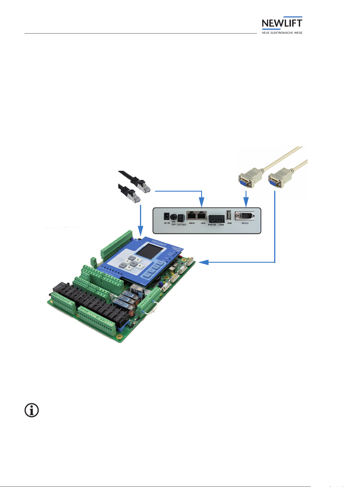
4.3 Controller side – Connecting PAM.E4 to FST
Depending on the version of the FST controller, set up the connection either via Ethernet or via RS232:
►For FST-2XT(s) controllers as of version V2.000-0152, use an Ethernet cable (patch cable):
•Connect the cable to the LAN port on the rear side of the PAM.E4 and to the LAN port of the FST.
•
OR
►For FST-1 and FST-2 controllers as well as FST-2XT(s) controllers up to version V2.000-0151, use an
RS232 cable (null modem):
•Connect the cable to the RS232 port on the rear side of the PAM.E4 and to the RS232 port of the
FST.
RS232
Ethernet
►After connecting the PAM.E4 and controller, check the IP settings of the FST:
See „5.4.1 Settings for connection to Elevision 4 / Connectivity“ on page 23 .
•IP: 192.168.7.10
•Mask: 255.255.255.0
•Server IP: 192.168.7.2
•Port number: 8002
Default settings can be changed.
Installation
PAM.E4 manual 13
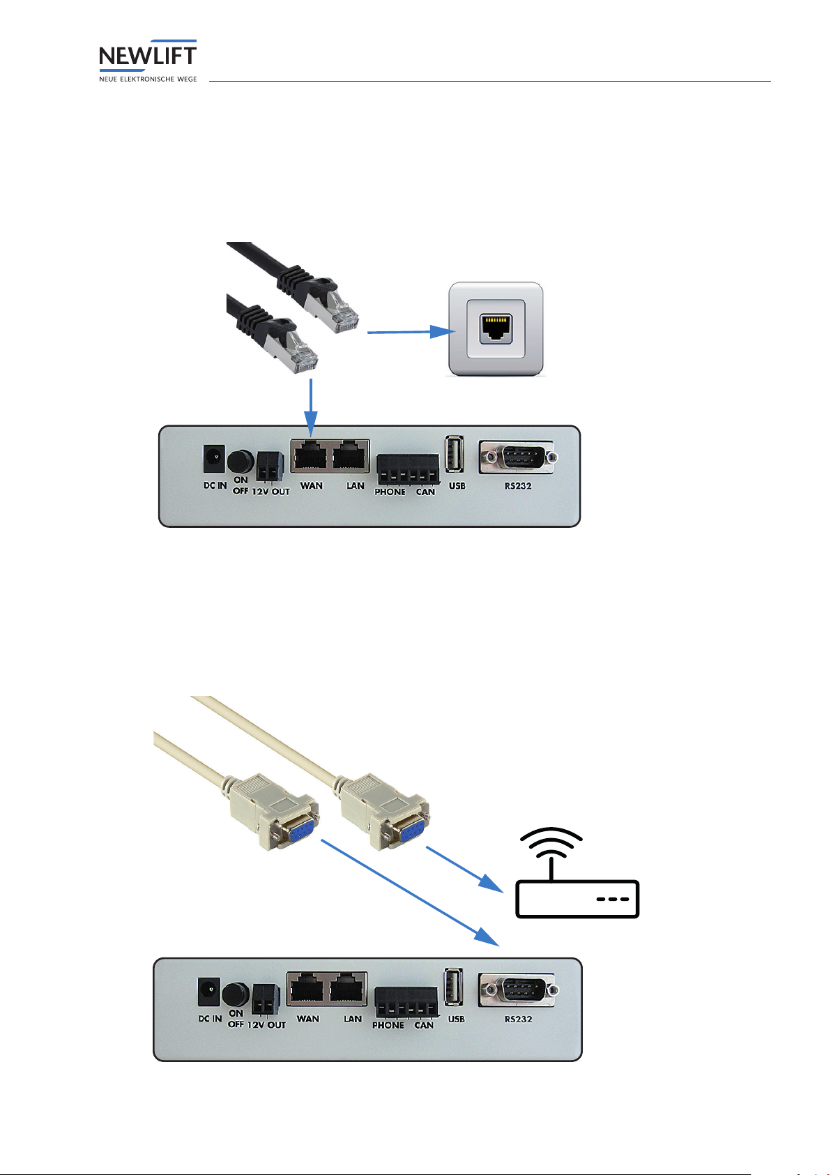
4.4 Serverside–ConnectiontoELEVISION4
4.4.1 Ethernet / Ethernet
►Connect the two connector plugs of the Ethernet cable
•to the WAN port on the rear side of the PAM.E4 and
•to the network socket.
►Check the IPsettings.
See „Conguration of WAN interface“ on page 24 .
4.4.2 RS232 / modem
►Connect the two connector plugs of the RS232 cable (null modem or 1:1, depending on the modem)
•to the RS232 port on the rear side of the PAM.E4 and
•to the modem.
►Check the modem settings.
See „Conguration of modem interface“ on page 25 .
Installation
14 PAM.E4 manual
Connection via modem is only possible for FST controllers as of version V2.000‑0152. On earlier versions,
the RS232 port must be reserved for connection to the FST.
Supported modems
›BASE GSM 13
(Software update of Base modem required, rmware: GSM13-U-3MR-R1.0.17-T9).
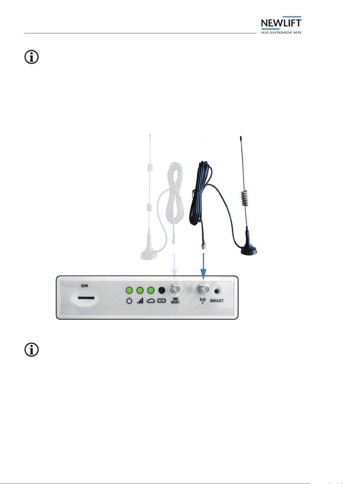
4.4.3 RS232 or Ethernet / LTE
►Connect the connector plug of the LTE antenna to the front side of the PAM.E4.
►Check the settings of the SIMcard.
To unlock the SIMcard:
Please contact the NEWLift service line. See „1.5 How to contact us“ on page 6 .
Installation
PAM.E4 manual 15
4.5 Connecting mains supply line (Power)
►Connect the supplied power supply cable to a 24VDC source at the control cabinet and connect to
the PAM.E4.
►Depending on the conguration, connect the mains cable in the control cabinet or plug in the mains
plug.
►Plug in the DCplug at the DC port on the rear side of the PAM.E4.
►Press the ON/OFF button.
Control cabinet 24 VDC
ON / OFF
4.6 Checking status of connection
►Watch the LEDs on the front side of the PAM.E4:
•The Power ON LED must light up green.
•When an LTE antenna is connected, the LTE LED must light up green.
•As soon as the connection to the E4 is set up, the Cloud LED lights up for approx. one minute.
1 2 3
1 LED – power ON 3 LED – E4 cloud connection
present
2 LED – LTE connection present
In the event of connection problems: See „7 FAQ“ on page 38 .

Configuration
16 PAM.E4 manual
5 Conguration
Precongured
The PAM.E4 units are usually delivered precongured and are immediately ready for use.
Notprecongured
A number of minimal conguration steps are required at the PAM.E4 so that the system can log in to
the Elevision4 server:
Requirements
›Laptop or PC with network port and appropriate conguration privileges
›Conguration of the network settings on the PC/laptop
IPaddress: 192.168.6.x (except for PAM.E4 gateway IP: 192.168.6.2)
Network mask: 255.255.255.0
MinimalPAM.E4conguration
►Set up the interface to the controller (Ethernet or RS232, controller type)
►Set up the interface to the Elevision4 server
(LTE, Ethernet, RS232, modem, connection behaviour, routine call, PAM.E4 wakeup, Elevision server)

Configuration
PAM.E4 manual 17
5.1 Login and logout
Login
►Make sure that an online connection is set up.
►Open any browser and enter the following IPaddress in the address bar
http://192.168.6.2
The login dialogue shown below appears.
►Enter the password 0000 and click on the Login button.
The Conguration Portal starts automatically.
The IPaddress and password can be changed.
Abb. 1 Login dialogue
Remember to log out of the Conguration Portal when you leave your workplace. This will prevent
unauthorisedpersonsfromviewingcondentialdata.
Logout
►Click on the logout icon at the top right edge of the screen.
The current settings are saved automatically.

Configuration
18 PAM.E4 manual
5.2 Menu structure
The following sections provide an overview of the structure of the Conguration Portal as well as infor-
mation on how to use the different interface elements.
5.2.1 Main window
The main window displays the respective working area, depending on which tab you have clicked in the
menu bar.
When the program is started for the rst time, the working area for the Status tab is displayed.
1
3 4
2
1 Menu bar with logout 3 Navigation area
2 Tabs 4 Information and conguration area
5.2.2 Menu and tabs
Menu
In the menu bar, you can select tabs, manage data and close the program again.
Tabs
You use the tabs to open the respective working area.
Abb. 2 Menu bar with tabs
Tabs Function
Opens the Status working area.
The Status working area displays the general state and statistics of
the gateway. Further options are available.
Configuration
PAM.E4 manual 19
Tabs Function
Opens the Gateway working area.
The Gateway working area contains the gateway conguration
for connectivity to the Internet and for behaviour with respect to
Elevision4, as well as general functions (e.g. import/export of the
conguration).
Opens the Controller working area.
The Controller working area contains the gateway conguration for
connectivity and behaviour with respect to the controller.
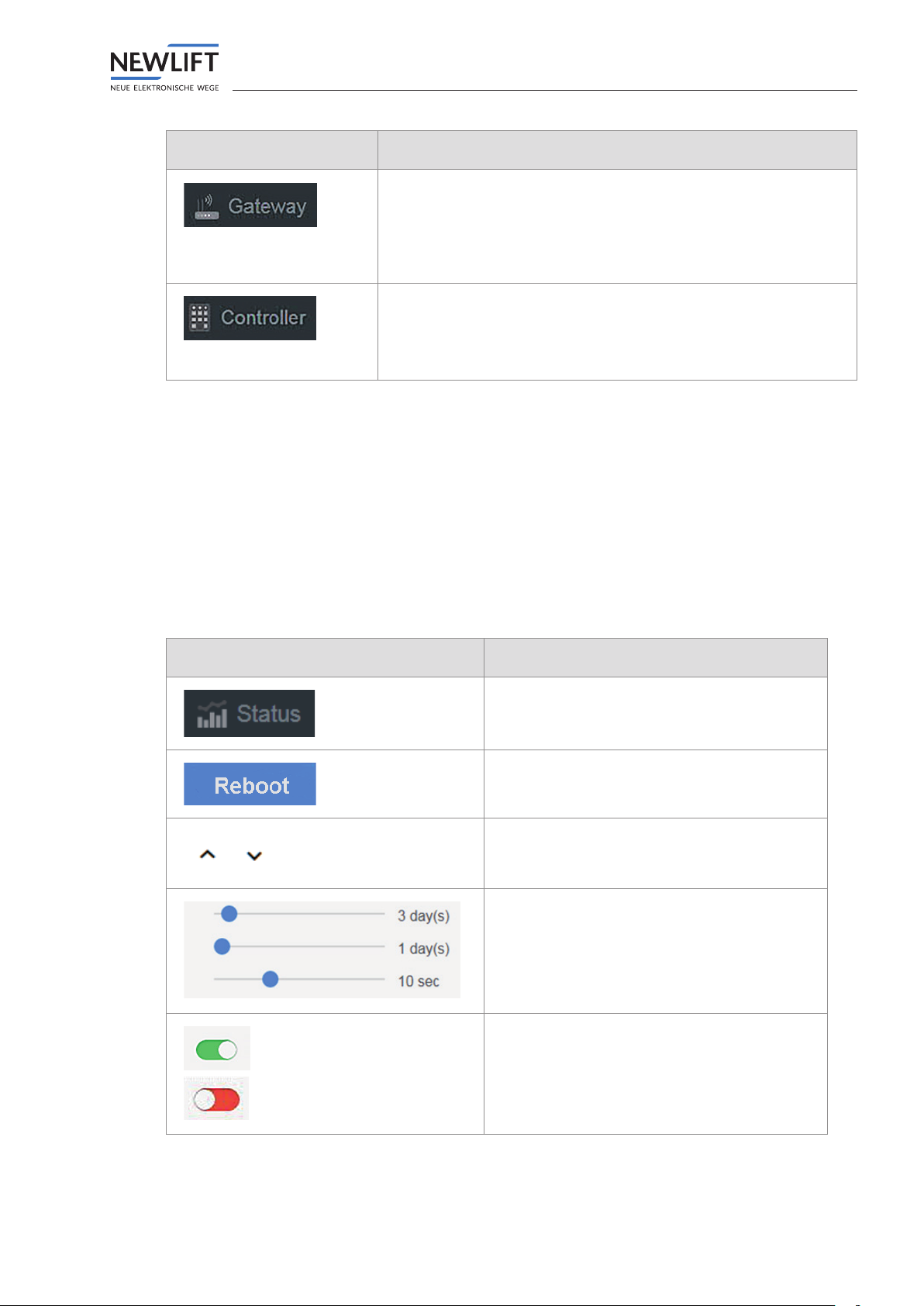
5.2.3 Buttons and slide controls
Buttons
You use buttons to conrm and leave a dialogue or to change to a different view or tab.
Slide controls
You use slide controls to
›switch conditions on or off or
›set values within a predened range.
Button Function
Opens the respective tab
Here e.g. the Status tab
Executes the respective action.
Here e.g. the gateway reboots.
Opens / closes a submenu
To change the value of the slide control:
►left-click the slide control handle
►hold down the mouse key and slide the
handle to the desired position.
The set value is displayed.
Switches a condition on/off
›green: switched on
›red: switched off

Configuration
20 PAM.E4 manual
5.3 Status tab
The Status tab starts in the Overview sub‑tab.
5.3.1 Overview
The quick overview
›shows the status of the connection to Elevision and to the controller
›shows the transmitted data volume (in bytes)
›shows information on the gateway (gateway type, system time, …)
›provides actions (reboot, download logs, …)
1
2 3
4
1 Quick overview showing Connection
status
3Elevision server area
2Controller area 4 Gateway area
Table of contents
Other New lift Gateway manuals


