Chipkin BEST CAS 2700-74 User manual

Toll Free: 1 866 383-1657
3381 Cambie St., #211 Vancouver, BC Canada V5Z 4R3
Chipkin™ BEST Gateway USER MANUAL
VERSION: 0.14
PRODUCT NUMBER: CAS 2700-74
DOCUMENT REVISION: 3

Chipkin™ BEST Gateway User Manual
3381 Cambie Street, #211 © 2018 Chipkin Automation Systems
Vancouver, BC, Canada, V5Z 4R3 All rights reserved
1-866-383-1657 Chipkin.com Page 2of 55
TABLE OF CONTENTS
TABLE OF CONTENTS .........................................................................................................................................2
LIST OF FIGURES ...................................................................................................................................................4
LIST OF TABLES .....................................................................................................................................................5
COPYRIGHT & TRADEMARKS ...........................................................................................................................6
DISCLAIMER ...........................................................................................................................................................6
CONFIDENTIALITY ...............................................................................................................................................6
DOCUMENT REVISION HISTORY.....................................................................................................................6
1. PREFACE..................................................................................................................................................................7
WELCOME ...................................................................................................................................................7
CHIPKIN........................................................................................................................................................7
SAFETY WARNINGS ..................................................................................................................................7
CUSTOMER SUPPORT ..............................................................................................................................7
2. OVERVIEW..............................................................................................................................................................9
PRODUCT SUMMARY...............................................................................................................................9
SYSTEM OVERVIEW..................................................................................................................................9
OPTIONAL EXPANSION MODULES......................................................................................................9
INSTALLATION AND CONFIGURATION SUMMARY........................................................................9
DEVICE WIRING REQUIREMENTS.........................................................................................................9
3. CONNECTIONS ...................................................................................................................................................10
NETWORK CONNECTIONS...................................................................................................................10
COMUNICATION PORTS .......................................................................................................................11
WIRING CONNECTIONS ........................................................................................................................11
4. CONFIGURATION AND SETTINGS.................................................................................................................12
Eniscope MQTT Configuration...............................................................................................................12
3rd Party BACnet Power Meter Configuration....................................................................................14
BEST Cloud Server Settings.........................................................................................................15
Add 3rd Party BACnet Power Meter ..........................................................................................16
Add Task to Read a Data Point from a 3rd Party BACnet Power Meter.............................17
Completing the Configuration ................................................................................................................18
Resetting the Gateway or Deleting the Configuration ......................................................................20
Exporting the Configuration....................................................................................................................21

Chipkin™ BEST Gateway User Manual
3381 Cambie Street, #211 © 2018 Chipkin Automation Systems
Vancouver, BC, Canada, V5Z 4R3 All rights reserved
1-866-383-1657 Chipkin.com Page 3of 55
Importing the Configuration....................................................................................................................21
5. READING DATA AND TEST PROCEDURE....................................................................................................24
READING DATA USING HTML / WEB Browser................................................................................24
READING BACNET DATA.......................................................................................................................25
Interpreting BACnet Data ............................................................................................................25
BACnet Object List ........................................................................................................................26
BACnet Test Procedure................................................................................................................28
6. COMMISIONING, DIAGNOSTICS, AND TROUBLE-SHOOTING .............................................................32
WHAT TO TAKE TO SITE FOR COMMISSIONING ..........................................................................32
Software...........................................................................................................................................32
Hardware .........................................................................................................................................32
DISCOVER GATEWAY’S IP ADDRESS.................................................................................................33
Setup reference card.....................................................................................................................33
Using the IP Setup tool .................................................................................................................34
DEFAULT USERNAME AND PASSWORD ..........................................................................................34
DEBUG LOG OR WIRESHARK LOG.....................................................................................................35
Debug logging.................................................................................................................................35
Wireshark log..................................................................................................................................35
CHANGE THE GATEWAY IP ADDRESS ..............................................................................................35
UPDATE FIRMWARE ...............................................................................................................................36
LIMITATIONS AND BEST PRACTICES................................................................................................................39
APPENDIX A: SAFETY WARNINGS.....................................................................................................................40
APPENDIX B: HARDWARE SPECIFICATIONS ..................................................................................................41
APPENDIX C: LIMITED WARRANTY...................................................................................................................45
APPENDIX D: USING CAS BACNET EXPLORER ..............................................................................................49
THANK YOU..............................................................................................................................................................55

Chipkin™ BEST Gateway User Manual
3381 Cambie Street, #211 © 2018 Chipkin Automation Systems
Vancouver, BC, Canada, V5Z 4R3 All rights reserved
1-866-383-1657 Chipkin.com Page 4of 55
LIST OF FIGURES
Figure 3.1-1. Network Connections Block Diagram..........................................................................................10
Figure 4.1-1 - BEST Config Link ............................................................................................................................12
Figure 4.1-2 - Eniscope Configuration Form.......................................................................................................12
Figure 4.2-1 - Other BACnet Meter Configuration Link ..................................................................................14
Figure 4.2-2 - Other BACnet Meter Configuration Form ................................................................................15
Figure 4.2-3 - Add 3rd Party BACnet Power Meter Link .................................................................................16
Figure 4.2-4 - Add 3rd Party BACnet Power Meter Form...............................................................................16
Figure 4.2-5 - Added 3rd Party BACnet Power Meter .....................................................................................17
Figure 4.2-6 - Add Data Point Link .......................................................................................................................17
Figure 4.2-7 - Add Data Point Form .....................................................................................................................17
Figure 4.2-8 - Added Data Point ...........................................................................................................................18
Figure 4.3-1 - Save Database Link ........................................................................................................................18
Figure 4.3-2 - Save Database Successful.............................................................................................................19
Figure 4.3-3 - Reboot System Link .......................................................................................................................19
Figure 4.3-4 - Reboot System Count....................................................................................................................19
Figure 4.4-1 - Delete Database Link.....................................................................................................................20
Figure 4.4-2 - Delete Database Successful .........................................................................................................20
Figure 4.5-1 - Generate Configuration File Link ................................................................................................21
Figure 4.6-1 - Import Configuration .....................................................................................................................21
Figure 4.6-2 - Import File Browser........................................................................................................................22
Figure 4.6-3 - Configuration File Ready for Import...........................................................................................22
Figure 4.6-4 - Importing the Configuration File .................................................................................................22
Figure 4.6-5 - Import Successful ...........................................................................................................................23
Figure 4.6-6 - Export Configuration .....................................................................................................................23
Figure 5.1-1 - Reports Link.....................................................................................................................................24
Figure 5.1-2 - Reports Page....................................................................................................................................25
Figure 5.3-1 –CAS BACnet Explorer - Devices were discovered..................................................................29
Figure 5.3-2- CAS BACnet Explorer –Device Selection ..................................................................................29
Figure 5.3-3 - CAS BACnet Explorer - Discover Dialogue...............................................................................30
Figure 5.3-4 - CAS BACnet Explorer - Discovered Objects.............................................................................31
Figure 5.3-5 - CAS BACnet Explorer - Single Object ........................................................................................31
Figure 6.1-1 - DB9 Gender Changers...................................................................................................................33
Figure 6.1-2 - RS232 Mini-Tester .........................................................................................................................33
Figure 6.2-1 Setup reference card ........................................................................................................................34
Figure 6.2-2 IP Setup tool.......................................................................................................................................34
Figure 6.5-1 IP Setup tool.......................................................................................................................................36
Figure 6.6-1 AutoUpdate tool window ................................................................................................................37
Figure 6.6-2 AutoUpdate tool window ................................................................................................................37
Figure 6.6-3 Firmware update success ................................................................................................................38

Chipkin™ BEST Gateway User Manual
3381 Cambie Street, #211 © 2018 Chipkin Automation Systems
Vancouver, BC, Canada, V5Z 4R3 All rights reserved
1-866-383-1657 Chipkin.com Page 5of 55
LIST OF TABLES
Table 1-1 - Document Revision History ................................................................................................................6
Table 3-1 - Communication Ports .........................................................................................................................11
Table 5-1 - Sample BACnet Object List ...............................................................................................................28

Chipkin™ BEST Gateway User Manual
3381 Cambie Street, #211 © 2018 Chipkin Automation Systems
Vancouver, BC, Canada, V5Z 4R3 All rights reserved
1-866-383-1657 Chipkin.com Page 6of 55
COPYRIGHT & TRADEMARKS
Copyright © 2018 Chipkin Automation Systems All rights reserved.
TM(TM) are trademarks of Chipkin Automation Systems
DISCLAIMER
Chipkin Automation Systems™ has limited its liability for damages incurred by the customer or its
personnel in the contractual documents pursuant to which the product is provided to the customer.
The information and specifications contained throughout this user manual are up to date at the time of
publication. Chipkin Automation Systems has used, and continues to use, its best efforts to maintain
this user manual to reflect the most current configuration of the product. Chipkin Automation Systems
reserves the right to change the contents of this user manual at any time without notice and assumes
no liability for its accuracy. In the preparation of this user manual, Chipkin Automation Systems has
incorporated, and/or compiled service information and maintenance procedures sourced from
manufacturers and vendors of parts and components used in the manufacturing of this product.
Therefore, Chipkin Automation Systems shall not be liable for omissions or missing data. It is not the
intension of this user manual to instruct service technicians in using common sense, basic skills and
rules of service repair.
CONFIDENTIALITY
The information contained in this document is the intellectual property of Chipkin Automation
Systems and is Commercially Confidential. No part of this document may be reproduced or
transmitted in any form or by any means, electronic or mechanical, for any purpose, without the
express written permission of Chipkin Automation Systems.
DOCUMENT REVISION HISTORY
REVISION
DATE
AUTHOR
NOTE
1
2018-May-10
ACF
- Created document
2
2018-May-11
ACF
- Updated description and block diagram
3
2018-June-11
ACF
- Added Appendix D with example of using CAS
BACnet Explorer to help configure the driver
Table 1-1 - Document Revision History

Chipkin™ BEST Gateway User Manual
3381 Cambie Street, #211 © 2018 Chipkin Automation Systems
Vancouver, BC, Canada, V5Z 4R3 All rights reserved
1-866-383-1657 Chipkin.com Page 7of 55
1. PREFACE
WELCOME
As a new owner of Chipkin Automation Systems’™ (CAS) Gateway you have joined thousands of
satisfied customers who use Chipkin’s protocol gateways, data clients and integration services to meet
their building and industrial automation requirements. Our configuration expertise in this field
combined with free BACnet and other tools ensure your success; and our customer support via phone,
email and remote desktop tools means that we’re there when you need us. Thank you for choosing
Chipkin’s products.
CHIPKIN
Chipkin offers expert solutions for your building and industrial automation requirements. We develop,
configure, install and support gateways (protocol converters), data loggers, and remote monitor and
controlling applications. Founded in October 2000, Chipkin provides expert solutions for converting
BACnet®, Modbus®, and Lonworks®—to name just a few—and enabling interfaces for HVAC, fire,
siren, intercom, lighting, transportation and fuel systems. The high-quality products we offer (including
those from other vendors) interface with Simplex™, Notifier™, McQuay™, GE™ and many others—so
you can rest assured that Chipkin will select the most appropriate solution for your application.
SAFETY WARNINGS
The CAS Gateway User Manual provides information on how to install and configure the gateway and
is intended for engineers, project management consultants and building management services. Before
you install the device, please observe the safety warnings described in in this manual.
CUSTOMER SUPPORT
Chipkin is a small responsive company, and we live or die by the quality of our service—and with
offices in two time-zones—we can provide support when you need it. For information on sales,
service, obtaining documentation or submitting a service request, please call us toll free at 1-866-383-
1657. Thanks for choosing Chipkin’s protocol gateways, data clients and integration services to meet
your building and industrial automation requirements.

Chipkin™ BEST Gateway User Manual
3381 Cambie Street, #211 © 2018 Chipkin Automation Systems
Vancouver, BC, Canada, V5Z 4R3 All rights reserved
1-866-383-1657 Chipkin.com Page 8of 55
SALES AND CUSTOMER SUPPORT
TOLL FREE: 1-866-383-1657
FAX: 1-416-915-4024
EMAIL: [email protected]
GENERAL
TOLL FREE: 1-866-383-1657
FAX: 1-416-915-4024
EMAIL: support@chipkin.com
SHIPPING ADDRESS
3381 Cambie St., #211
Vancouver, BC, Canada V5Z 4R3

Chipkin™ BEST Gateway User Manual
3381 Cambie Street, #211 © 2018 Chipkin Automation Systems
Vancouver, BC, Canada, V5Z 4R3 All rights reserved
1-866-383-1657 Chipkin.com Page 9of 55
2. OVERVIEW
PRODUCT SUMMARY
The BEST Eniscope to BACnet IP and HTTP gateway is a protocol converter for the BEST Eniscope
Power Meter system. The gateway operates by receiving data from the Eniscope system and storing
the parse values internally. These values can then be read using BACnet® and via the web page. The
gateway also allows users to read data from other BACnet Power Meters and serve the data using
HTTP POSTs to a BEST Cloud Server for further analysis.
The gateway requires minimal configuration and can be considered a ‘plug and play’ component of any
network system. It’s ready to operate ‘out of the box’ and can be installed without an engineer’s
approval.
SYSTEM OVERVIEW
The BEST Gateway is a protocol converter that converts data from one protocol and makes it available
to devices that support a different protocol. The gateway typically sends polling messages, extracts
any data values, and stores the values in an internal database. The data is then made available via
other protocol specific formats.
OPTIONAL EXPANSION MODULES
The BEST Gateway does not have any optional expansion modules.
INSTALLATION AND CONFIGURATION SUMMARY
For more information on how to install and setup the BEST Gateway please refer to the CAS Gateway
Quick Start Guide. For instructions on configuring this device, please refer to Configuration and
Settings Section of this document. Configuration of the device is completed primarily through a web
interface.
DEVICE WIRING REQUIREMENTS
For more information on how to wire up the BEST Gateway, please refer to the Connections section
of this document. The Connections Section contains wiring pictures and diagrams (if applicable) as
well as port pin-outs.

Chipkin™ BEST Gateway User Manual
3381 Cambie Street, #211 © 2018 Chipkin Automation Systems
Vancouver, BC, Canada, V5Z 4R3 All rights reserved
1-866-383-1657 Chipkin.com Page 10 of 55
3. CONNECTIONS
NETWORK CONNECTIONS
This block diagram lists common network connections that can monitor BEST Eniscope Power Meters
using BACnet IP and can read BACnet IP Power Meters and push the data to a BEST cloud server.
Figure 3.1-1. Network Connections Block Diagram

Chipkin™ BEST Gateway User Manual
3381 Cambie Street, #211 © 2018 Chipkin Automation Systems
Vancouver, BC, Canada, V5Z 4R3 All rights reserved
1-866-383-1657 Chipkin.com Page 11 of 55
COMUNICATION PORTS
The Gateway uses the following ports for communication over the ethernet port.
Protocol
Port
Notes
HTTP
TCP 80
Web server, not configurable.
Syslog
UDP 514
Can be disabled.
FTP
TCP 21
Can be disabled, requires Firmware Update
MQTT
TCP 1883
Configurable.
BACnet IP
UDP 47808
Configurable.
Table 3-1 - Communication Ports
WIRING CONNECTIONS
The BEST Gateway only uses the ethernet port for communication. Use a standard ethernet patch
cable to connect the gateway to the network. For more information on changing the IP Address of the
gateway, please refer to section 6.5 Change the Gateway IP Address.
Chipkin™ BEST Gateway User Manual
3381 Cambie Street, #211 © 2018 Chipkin Automation Systems
Vancouver, BC, Canada, V5Z 4R3 All rights reserved
1-866-383-1657 Chipkin.com Page 12 of 55
4. CONFIGURATION AND SETTINGS
This section contains instructions and screenshots on how to configure this device
Eniscope MQTT Configuration
Follow these steps to setup the BEST Gateway to receive data from Eniscope Power Meters.
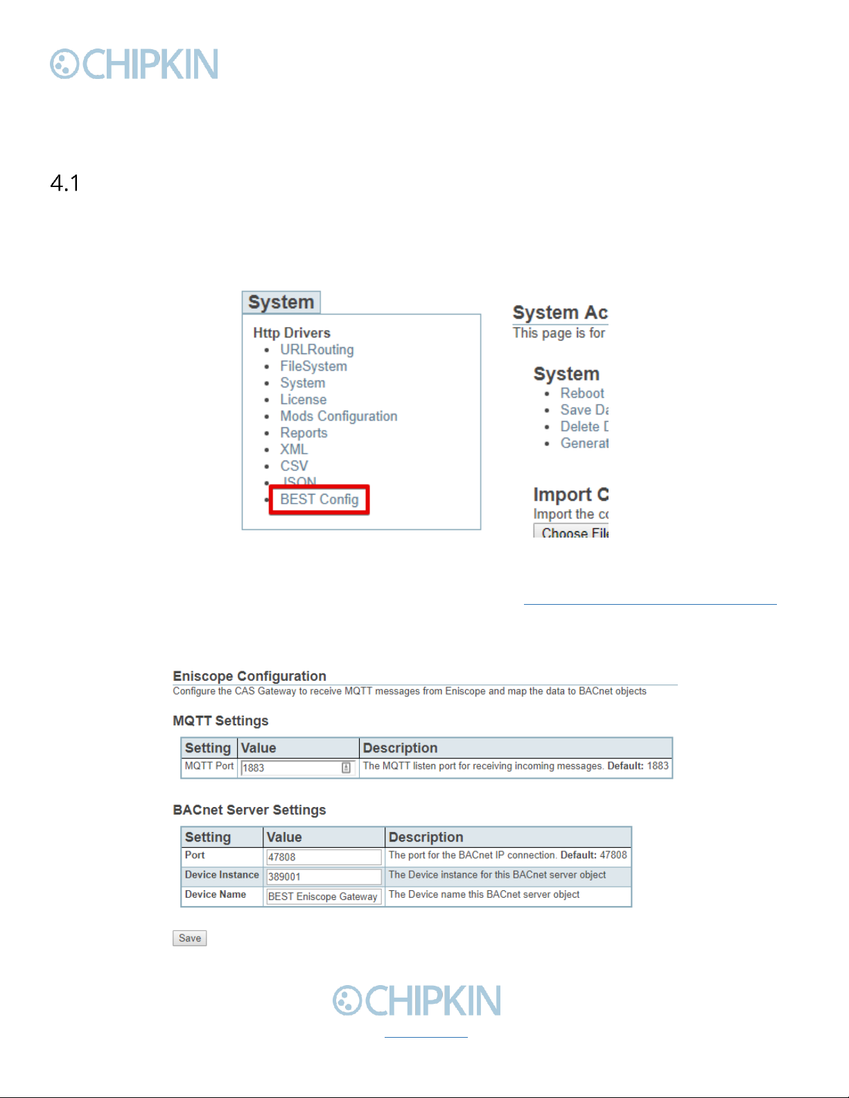
First, browse to the configuration page by clicking on the ‘BEST Config’ link as shown in the image
below:
Figure 4.1-1 - BEST Config Link
Or type the following url into the address bar of a web browser: http://{ipAddress}/bin/best/config
where {ipAddress} is the IP Address of the BEST Gateway.
On the BEST Config page, you will see the following form:
Figure 4.1-2 - Eniscope Configuration Form

Chipkin™ BEST Gateway User Manual
3381 Cambie Street, #211 © 2018 Chipkin Automation Systems
Vancouver, BC, Canada, V5Z 4R3 All rights reserved
1-866-383-1657 Chipkin.com Page 13 of 55
The form has the following fields:
MQTT Settings
•MQTT Port –The MQTT listen port for receiving incoming messages. Default: 1883.
BACnet Server Settings
•Port –The port for the BACnet IP connection. Default: 47808
•Device Instance –The Device instance for this BACnet server object.
•Device Name –The Device name for this BACnet server object.
Fill out the fields and click the ‘Save’ button to save the settings.
Note: If either the MQTT Port or BACnet Port settings were changes, please reboot the gateway for
the changes to take effect. For more information on how to reboot the gateway, please refer to
section 4.3 Completing the Configuration.
After saving the settings and possibly rebooting the device, the gateway is ready to accept Eniscope
data. As the gateway received data, it will auto-configure the mapped BACnet objects. You can view
the full list of BACnet objects in the reports page. For more information about the reports page,
please refer to section 5.1 Reading Data Using HTML/Web Browser
Use the reports page to confirm that the expected data points exist. Finally save the configuration and
reboot the gateway.
Chipkin™ BEST Gateway User Manual
3381 Cambie Street, #211 © 2018 Chipkin Automation Systems
Vancouver, BC, Canada, V5Z 4R3 All rights reserved
1-866-383-1657 Chipkin.com Page 14 of 55
3rd Party BACnet Power Meter Configuration
Follow these steps to configure the BEST Gateway to read data from other BACnet IP Power Meters
and push the data to a BEST Cloud Server.
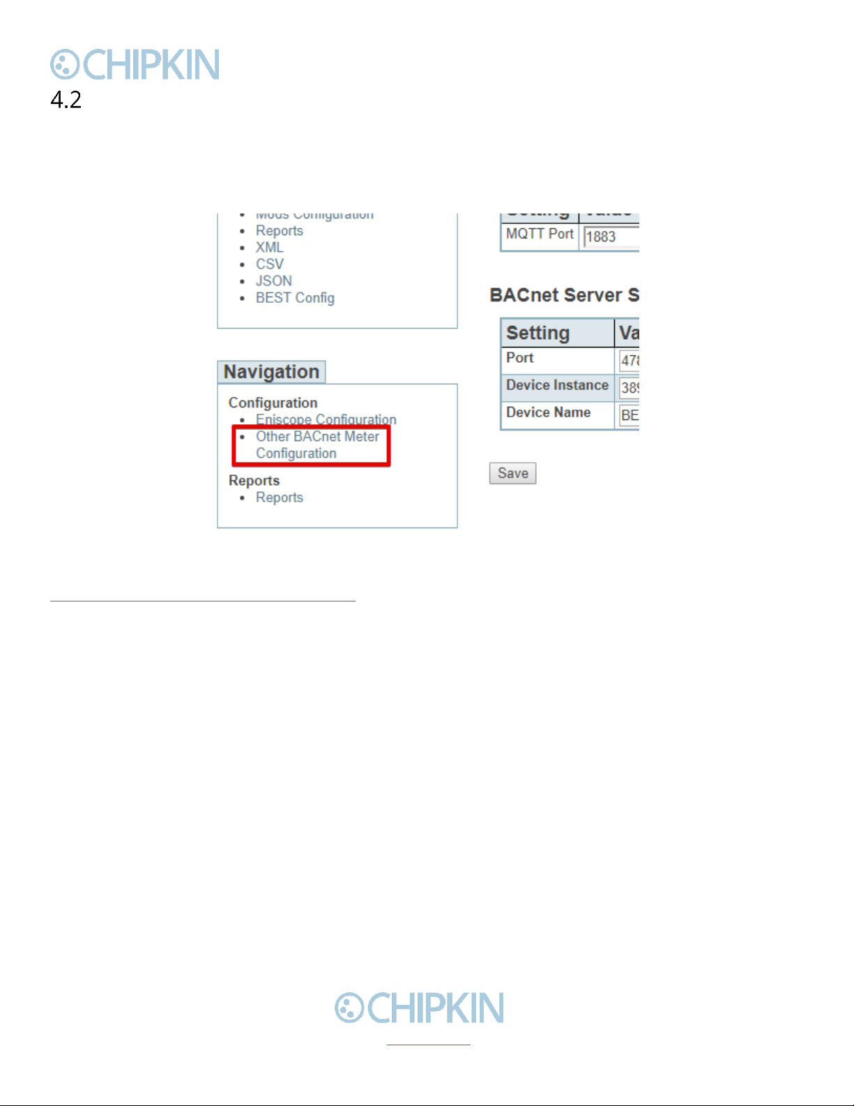
First, browse to the Other BACnet Meter Configuration page by clicking on the link as show in the
image below:
Figure 4.2-1 - Other BACnet Meter Configuration Link
Or type the following url into the address bar of a web browser:
http://{ipAddress}/bin/best/bacnetconfig where {ipAddress} is the IP Address of the BEST Gateway.
You will see the following form:

Chipkin™ BEST Gateway User Manual
3381 Cambie Street, #211 © 2018 Chipkin Automation Systems
Vancouver, BC, Canada, V5Z 4R3 All rights reserved
1-866-383-1657 Chipkin.com Page 15 of 55
Figure 4.2-2 - Other BACnet Meter Configuration Form
BEST Cloud Server Settings
The first part of the form is used to set the cloud server settings. The fields are:
•Host –The host for the cloud server.
•Port –The port for the cloud server. Default: 80, use 443 for https.
•Post url –The url to send the HTTP POST containing the meter data.
•Post Interval –How often to send the HTTP POST in seconds. Default: 60
Click the ‘Save Cloud Server Settings’ button to save the cloud server settings.

Chipkin™ BEST Gateway User Manual
3381 Cambie Street, #211 © 2018 Chipkin Automation Systems
Vancouver, BC, Canada, V5Z 4R3 All rights reserved
1-866-383-1657 Chipkin.com Page 16 of 55
Add 3rd Party BACnet Power Meter
Next, add the BACnet Power Meter device information. Before doing this, please contact BEST with a
list of the BACnet Device Instances that these power meters have, and BEST will provide UIDs to
assign to each one of them.
To add a power meter, first click on the ‘Insert’ link as shown in the image below:
Figure 4.2-3 - Add 3rd Party BACnet Power Meter Link
You will see this form:
Figure 4.2-4 - Add 3rd Party BACnet Power Meter Form
Fill out the fields as follows:
•Assigned UID –The UID provided by BEST to represent this BACnet Power Meter.
•IP Address –The IP Address of the BACnet Power Meter.
•Port –The BACnet Port of the BACnet Power Meter. Default: 47808
•BACnet Device Instance –The Device Instance of the BACnet Power Meter
•BACnet Network –The BACnet network that this device is on. Default: 0 (Local Network).
•BACnet Device SADR –The Source Address of the device. Only provide this if the network is
not zero.
Once the fields are filled out, click the ‘insert’ button. You will see the entry in the table if successful,
otherwise, any errors will be displayed at the top of the page.

Chipkin™ BEST Gateway User Manual
3381 Cambie Street, #211 © 2018 Chipkin Automation Systems
Vancouver, BC, Canada, V5Z 4R3 All rights reserved
1-866-383-1657 Chipkin.com Page 17 of 55
Figure 4.2-5 - Added 3rd Party BACnet Power Meter
Repeat these steps for each power meter.
Refer to Appendix D: Using CAS BACnet EXPLORER for information on how to use the CAS BACnet
Explorer to get the data to input into the configuration fields when adding a 3rd party BACnet Power
Meter.
Add Task to Read a Data Point from a 3rd Party BACnet Power Meter
Finally, add the data points to push to the BEST Cloud Server.
Click on the ‘Insert’ link as show in the image below:
Figure 4.2-6 - Add Data Point Link
You will see this form:
Figure 4.2-7 - Add Data Point Form
Fill out the fields as follows:
•UID –The UID that represents the device this object is from. The drop-down menu contains
the list of UIDs that were added in section 4.2.2.
•Data Type –The type of data point this task will read.
•BACnet Object Type –The BACnet Object type for this data point.
Chipkin™ BEST Gateway User Manual
3381 Cambie Street, #211 © 2018 Chipkin Automation Systems
Vancouver, BC, Canada, V5Z 4R3 All rights reserved
1-866-383-1657 Chipkin.com Page 18 of 55
•BACnet Object Instance –The BACnet Object instance for this data point.
•Scan Interval –How often to poll for the data point in seconds. Default: 30.
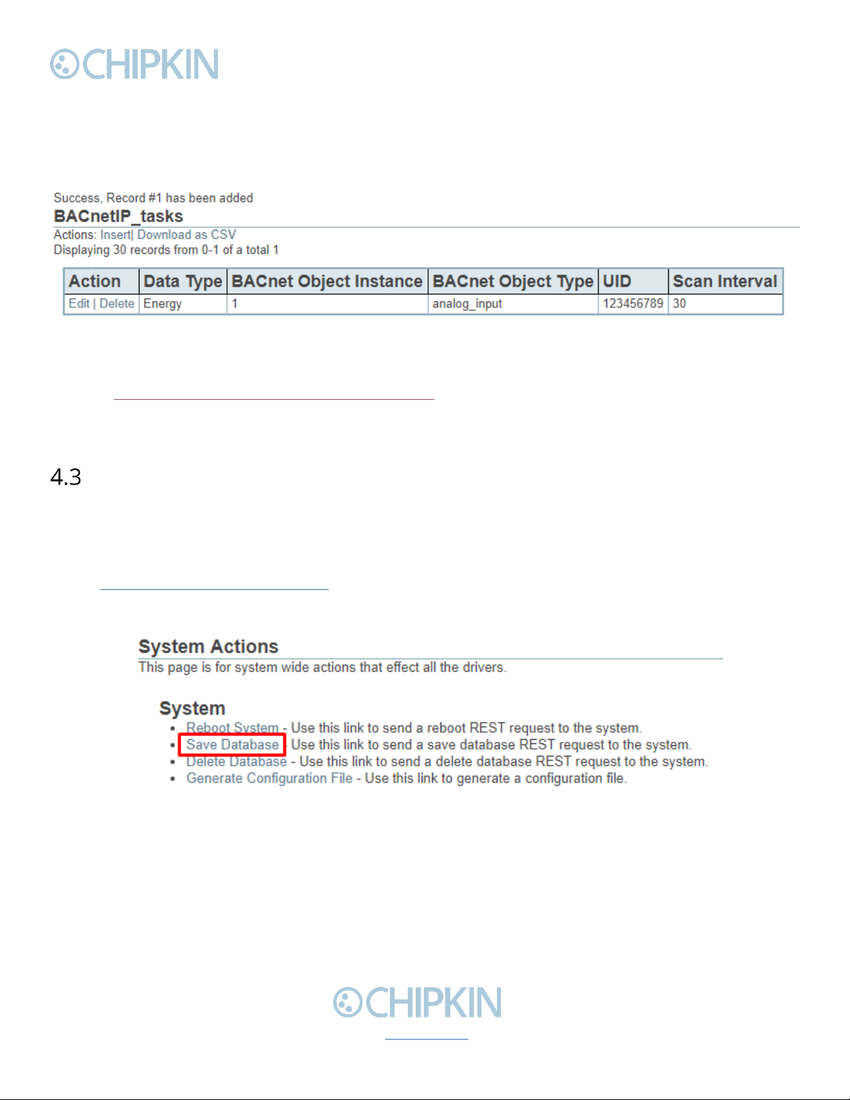
Click the ‘insert’ button once the fields have been filled out. You will see the entry in the table if
successful. Otherwise, any errors will be displayed at the top of the page.
Figure 4.2-8 - Added Data Point
Refer to Appendix D: Using CAS BACnet EXPLORER for information on how to use the CAS BACnet
Explorer to get the data to input into the configuration fields when adding a data point for a 3rd party
BACnet Power Meter.
Completing the Configuration
Once the configuration process has finished, you will need to reboot the system for the new
configuration to take effect.
First, return to the main system page by typing in the follow URL into a web browser:
-http://{ipAddress}/bin/system/ where {ipAddress} is the IP Address of the gateway.
From this page, under the System actions, first click the “Save Database” link to save all changes.
Figure 4.3-1 - Save Database Link
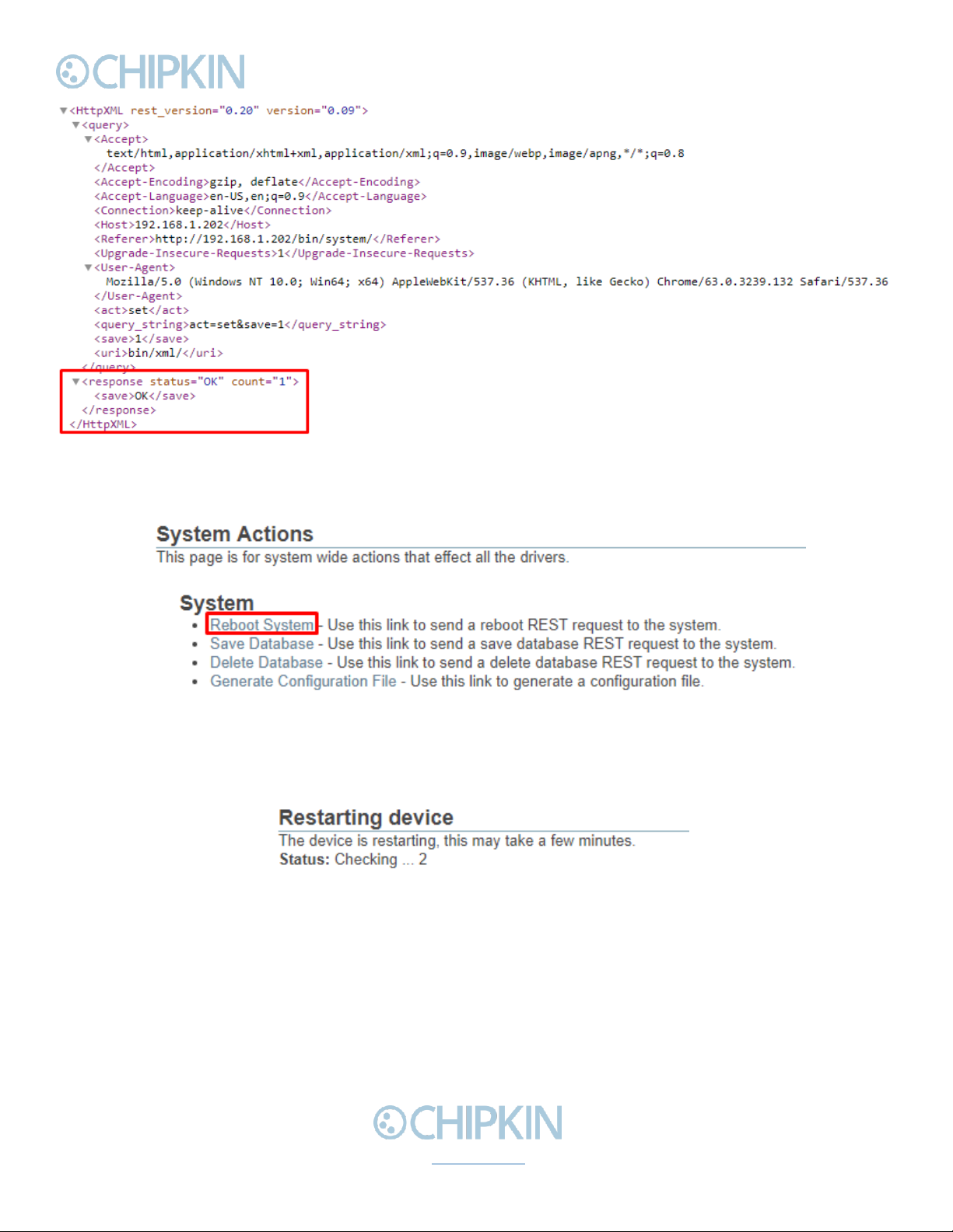
Click “Ok” when prompted and you will see the following XML, check that the response status is OK.
Chipkin™ BEST Gateway User Manual
3381 Cambie Street, #211 © 2018 Chipkin Automation Systems
Vancouver, BC, Canada, V5Z 4R3 All rights reserved
1-866-383-1657 Chipkin.com Page 19 of 55
Figure 4.3-2 - Save Database Successful
Click the back button in your web browser and then click the “Reboot System” link:
Figure 4.3-3 - Reboot System Link
Click “Ok” when prompted and you will see the following screen with a timer counting up:
Figure 4.3-4 - Reboot System Count
The system page will refresh once the device has been properly rebooted.

Chipkin™ BEST Gateway User Manual
3381 Cambie Street, #211 © 2018 Chipkin Automation Systems
Vancouver, BC, Canada, V5Z 4R3 All rights reserved
1-866-383-1657 Chipkin.com Page 20 of 55
Resetting the Gateway or Deleting the Configuration
Sometimes you want to delete the entire configuration and begin again. To do this, return to the
system page as described in the Completing the Configuration section above. Then click on the
“Delete Database” Link:
Figure 4.4-1 - Delete Database Link
Click “Ok” when prompted and verify that the result XML has a response status of OK:
Figure 4.4-2 - Delete Database Successful
Click the back button in the web browser and then follow the instructions in the Completing the
Configuration section.
Table of contents
Other Chipkin Gateway manuals


Popular Gateway manuals by other brands

WELLTECH
WELLTECH ATA-S user guide

WePresent
WePresent WiPG-1000 Deployment guide

ZyXEL Communications
ZyXEL Communications USG60 quick start guide

Denwa Communications
Denwa Communications DW-GTW-AC-E1030 Quick installation guide

ProSoft
ProSoft PLX51-PBS user manual

Visual Circuits
Visual Circuits MG user manual


