Newave PowerValue 11 User manual
PowerValueTM 11 and 31
Newave_OPM_PV11_PV31 _GB_250805.doc Page 1
User Manual
POWERVALUETM 11 and 31
Single-phase UPS System
7.5 - 20kVA
CABINET
A
CABINET B CABINET C

Newave_OPM_PV11_PV31 _GB_250805.doc Contents Page 2
CONTENTS
1SAFETY ...................................................................................................................................................... 4
2DESCRIPTION............................................................................................................................................ 5
2.1 RELIABILITY AND QUALITY STANDARDS......................................................................................5
2.2 POWERVALUE MODELS..................................................................................................................5
2.3 WARRANTY.......................................................................................................................................5
2.4 EXTENDED WARRANTY .................................................................................................................. 6
3INSTALLATION.......................................................................................................................................... 7
3.1 INTRODUCTION................................................................................................................................7
3.1.1 Receipt of the UPS ........................................................................................................................7
3.1.2 Nameplate......................................................................................................................................7
3.2 UNPACKING ...................................................................................................................................... 7
3.3 BATTERIES .......................................................................................................................................7
3.4 STORAGE..........................................................................................................................................8
3.4.1 UPS................................................................................................................................................8
3.4.2 Battery............................................................................................................................................8
3.5 POSITIONING....................................................................................................................................8
3.6 CABLING............................................................................................................................................9
3.6.1 Cabling of POWERVALUE 7.5, 10 and 12kVA with SINGLE PHASE INPUT..............................9
3.6.2 Connection Diagram ......................................................................................................................9
3.6.3 Preparation for the Input Cabling...................................................................................................9
3.6.4 Earthing..........................................................................................................................................9
3.6.5 Connection of the Mains Supply ..................................................................................................10
3.6.6 Single Input Feed.........................................................................................................................10
3.6.7 Dual Input Feed ...........................................................................................................................11
3.6.8 Preparation for the Output Cabling ..............................................................................................11
3.6.9 Connection of the Load................................................................................................................11
3.6.10 Output Cabling.........................................................................................................................12
3.6.11 How to fix the POWERVALUE to the floor .............................................................................. 12
3.6.12 Cabling of POWERVALUE 7.5, 10, 12, 15 and 20kVA with THREE PHASE INPUT ............. 14
3.6.13 Connection Diagram................................................................................................................14
3.6.14 Preparation for the Three Phase Input Cabling....................................................................... 14
3.6.15 Earthing ...................................................................................................................................14
3.6.16 Connection of the Mains Supply.............................................................................................. 15
3.6.17 Single Input Feed ....................................................................................................................15
3.6.18 Dual Input Feed .......................................................................................................................15
3.6.19 Preparation for the Output Cabling3........................................................................................16
3.6.20 Connection of the Load ...........................................................................................................16
3.6.21 Output Cabling.........................................................................................................................17
3.6.22 How to fix the POWERVALUE to the floor .............................................................................. 17
3.7 CONNECTION OF EXTERNAL BATTERÎES FOR UPS POWERVALUE .....................................20
3.8 INTERFACING .................................................................................................................................21
3.8.1 SMART PORT (Serial RS 232).................................................................................................... 21
3.8.2 DRY PORT (volt-free contacts)....................................................................................................22
4OPERATION............................................................................................................................................. 23
4.1 COMMISSIONING ...........................................................................................................................23
4.2 CONTROL PANEL...........................................................................................................................23
4.2.1 Power Management Display (PMD) ............................................................................................ 23
4.2.2 LED Indicators .............................................................................................................................24
4.2.3 Keys .............................................................................................................................................24
4.2.4 ON/OFF Start-up and Shutdown Buttons ....................................................................................25
4.3 DESCRIPTION OF THE LCD ..........................................................................................................26
4.3.1 Status Screens.............................................................................................................................26

Newave_OPM_PV11_PV31 _GB_250805.doc Contents Page 3
4.3.2 Main Menu Screen.......................................................................................................................26
4.3.3 Event Log Screen ........................................................................................................................26
4.3.4 Measurements Screen.................................................................................................................26
4.3.5 Commands Screen ......................................................................................................................27
4.3.6 UPS Data .....................................................................................................................................27
4.3.7 Set-Up User .................................................................................................................................27
4.3.8 Set-Up Service.............................................................................................................................28
4.4 OPERATING MODES......................................................................................................................29
4.4.1 Mode "ON LINE" (INVERTER MODE) ........................................................................................29
4.4.2 Mode "OFF-LINE" (ECO- or BYPASS MODE)............................................................................29
4.4.3 "MAINTENANCE BYPASS" - Mode.............................................................................................30
4.5 START-UP PROCEDURE ...............................................................................................................31
4.6 SHUTDOWN PROCEDURE ............................................................................................................33
4.7 LOAD TRANSFER: FROM INVERTER OPERATION TO MAINTENANCE BYPASS....................34
4.8 LOAD TRANSFER: FROM MAINTENANCE BYPASS TO INVERTER OPERATIONS..................35
5MAINTENANCE ....................................................................................................................................... 36
5.1 INTRODUCTION..............................................................................................................................36
5.2 USER RESPONSIBILITIES .............................................................................................................36
5.3 ROUTINE MAINTENANCE..............................................................................................................36
5.4 BATTERY TEST...............................................................................................................................36
6TROUBLESHOOTING ............................................................................................................................. 37
6.1 ALARMS...........................................................................................................................................37
6.2 MENU, COMMANDS, EVENT LOG, MEASUREMENTS,...............................................................37
6.3 FAULT IDENTIFICATION AND RECTIFICATION...........................................................................37
7OPTIONS .................................................................................................................................................. 38
7.1 INTRODUCTION..............................................................................................................................38
7.2 REMOTE EMERGENCY FACILITIES .............................................................................................38
7.3 REMOTE SIGNALLING PANEL (RSP)............................................................................................39
7.3.1 How to Connect the Remote Signaling Panel (RSP)...................................................................40
7.4 GENERATOR ON FACILITIES........................................................................................................40
7.5 WAVEMON SHUTDOWN AND MANAGEMENT SOFTWARE .......................................................41
7.5.1 Why is UPS Management important?..........................................................................................41
7.5.2 Wavemon Shutdown and Monitoring Software............................................................................41
7.6 SNMP CARD/ADAPTER FOR NETWORK MANAGEMENT /REMOTE MONITORING ................43
8TECHNICAL SPECIFICATIONS.............................................................................................................. 44
Newave_OPM_PV11_PV31 _GB_250805.doc Safety Page 4
1Safety
BEFORE ATTEMPTING TO INSTALL OR START UP THIS UPS THE USER MUST
ENSURE THAT THE SAFETY INSTRUCTIONS IN THIS MANUAL ARE CAREFULLY
READ AND OBSERVED BY TECHNICALLY COMPETENT PERSONNEL. KEEP THIS
MANUAL WITH THE UPS FOR FUTURE REFERENCE.
THIS UPS MUST NOT BE STARTED UP OR PUT INTO USE WITHOUT HAVING BEEN
COMMISSIONED BY A FULLY TRAINED AND AUTHORISED PERSON.
ALL SERVICING MUST BE PERFORMED ONLY BY QUALIFIED PERSONNEL. DO NOT
ATTEMPT TO SERVICE THE UPS YOURSELF.
BY OPENING OR REMOVING THE UPS-COVERS YOU RUN RISK OF EXPOSURE TO
DANGEROUS VOLTAGES!
IN CASE OF ANY KIND OF DOUBT REGARDING THIS UPS, CONTACT:
«NEWAVE SA, SWITZERLAND
Tel. +41 91 850 29 29
Fax. +41 91 840 12 54
www.newave.ch
NEWAVE SA WILL ASSUME NEITHER RESPONSIBILITY NOR LIABILITY DUE TO
INCORRECT OPERATION OR MANIPULATION OF THE UPS.
HIGH LEAKAGE CURRENT!
MAKE SURE THAT THE EARTHING IS CARRIED OUT CORRECTLY BEFORE YOU
CONNECT THE MAINS POWER SUPPLY!
THE POWERVALUE 7.5-20 kVA IS CLASS A - UPS-PRODUCT (ACCORDING TO EN
50091/Part-2).
IN A DOMESTIC ENVIRONMENT IT MAY CAUSE RADIO INTERFERENCE. IN SUCH AN
ENVIRONMENT THE USER MAY BE REQUIRED TO UNDERTAKE ADDITIONAL
MEASURES.
NEWAVE S.A. HAS TAKEN EVERY PRECAUTION TO PRODUCE AN ACCURATE,
COMPLETE AND EASY TO UNDERSTAND MANUAL AND WILL THEREFORE ASSUME
NO RESPONSIBILITY NOR LIABILITY FOR DIRECT, INDIRECT OR ACCIDENTAL
PERSONAL OR MATERIAL DAMAGE DUE TO ANY MISINTERPRETATION OR
UNDESIRED MISTAKES IN THIS MANUAL.
THIS MANUAL MAY NOT BE COPIED NOR REPRODUCED PRIOR TO WRITTEN
PERMISSION OF NEWAVE SA.
USER MUST HANG A WARNING LABEL ON ALL PRIMARY UPS POWER ISOLATORS.
ELECTRICAL MAINTENANCE PERSONNEL SHOULD BE AWARE OF DANGEROUS
VOLTAGES. THE WARNING LABEL SHOULD CARRY THE FOLLOWING WORDING:
“ISOLATE UPS BEFORE WORKING ON THIS CIRCUIT”
!
!
!
!
!

Newave_OPM_PV11_PV31 _GB_250805.doc Description Page 5
2Description
2.1 RELIABILITY AND QUALITY STANDARDS.
Congratulation on your purchase of the PowerValueTM.
The PowerValueTM will provide your critical equipment with a steady and reliable power supply for
many years.
NEWAVE SA is situated in Switzerland and is specialized in the design and manufacture of
Uninterruptible Power Supplies.
The unique and modular UPS PowerValueTM belongs to the newest generation of midrange 3phase
UPS-Systems. High reliability, low operating cost and excellent electrical performance are only some
of the highlights of this innovative UPS solution.
The criteria and methods implemented at NEWAVE SA for the design and manufacture correspond to
the most stringent quality standards.
The Swiss Association for Quality and Management System (SQS) certified that, according to the
model of the International Standard ISO 9001/EN 29001, the whole Newave SA company complies
successfully. (Registration No.: 14879-01, date issued: 12 April 1999.)
2.2 POWERVALUE MODELS
The PowerValueTM UPS series consists of:
Single Phase Input/Single Phase Output Models: 7.5, 10 and 12kVA
Three Phase Input/Single Phase Output Models: 7.5,10,15 and 20kVA
2.3 WARRANTY
The PowerValueTM is supplied with a limited warranty that the UPS and its component parts are free
from defects in materials for a period of 12 months from the date of original commissioning or 15
months from the date of original delivery, whichever is the sooner. Transportation cost is not included
in the warranty and has to be paid by the end-user.
Do not return anything without written authorisation from NEWAVE or your closest service centre.
NEWAVE or the closest service centre will then give you further instructions how to proceed.
Any product must be returned with transportation charges prepaid and must be accompanied by a
description of the failure. Products without description will not be handled.
This warranty is invalidated if the UPS is put into use without having been commissioned by a fully
trained and by NEWAVE authorised person.
This warranty does not apply to any damage or losses caused by misuse, abuse, negligence, neglect,
unauthorised repair or modification, incorrect installation, inappropriate environment, accident, act of
God or inappropriate application.
If the UPS fails to conform to the above within the warranty period then NEWAVE SA or an authorized
service centre will, at its sole option, repair or replace the UPS or parts of it. All repaired or replaced
parts will remain the property of NEWAVE or of the authorized service centre.
NEWAVE is not liable for any costs, such as loss of profits or revenue, loss of equipment, loss of data
or software, cost of substitutes, claims by third parties or otherwise.
As general policy, NEWAVE does not recommend the use of any of its products in life support
applications where failure or malfunction of the NEWAVE product can be reasonably expected to
cause failure of the life support device or to significantly affect us safety or effectiveness. NEWAVE

Newave_OPM_PV11_PV31 _GB_250805.doc Description Page 6
does not recommend the use of any of its products in direct patient care. NEWAVE will not knowingly
sell its products for use in such applications unless it receives in writing assurances satisfactory to
NEWAVE that the risks of injury or damage have been minimized, the customer assumes all such risks
and the liability of NEWAVE is adequately protected under the circumstances.
The UPS may contain batteries that must be re-charged for a minimum of 24 hours every 6
months to prevent deep discharging. Batteries that have been, for whatever reason, deep
discharged are not covered by the warranty.
2.4 EXTENDED WARRANTY
The standard warranty may be enhanced by protecting the UPS with an Extended Warranty
Agreement (maintenance contract).
For more details please contact the nearest representative.
!

Newave_OPM_PV11_PV31 _GB_250805.doc Installation Page 7
3Installation
3.1 INTRODUCTION
This chapter contains all the necessary information for the correct unpacking, positioning, cabling and
installation of the UPS PowerValueTM.
ALL THE OPERATIONS IN THIS SECTION MUST BE PERFORMED BY AUTHORISED
ELECTRICIANS OR BY QUALIFIED PERSONNEL.
NEWAVE will take no responsibility for any personal or material damage caused by
incorrect cabling or operations or activities, which are not carried out as per the
instructions contained in this manual.
3.1.1 Receipt of the UPS
Upon receiving the UPS, carefully examine the packing container and the UPS for any sign of physical
damage. In case of rupture or suspect inform immediately:
a) The carrier and
b) NEWAVE SA.
Ensure that the received UPS corresponds to the material indicated in the delivery note.
The packing container of the PowerValueTM protects it from mechanical and environmental damage.
To increase its protection the UPS is wrapped with a plastic sheet.
3.1.2 Nameplate
The technical specifications of the PowerValueTM are provided on the nameplate, which is situated at
the front of the UPS. Check if it corresponds to the purchased material mentioned in the delivery note.
3.2 UNPACKING
When unpacking the UPS observe the "FRAGILE" and "ARROW" on the packing container.
Perform the following steps to unpack the UPS:
• Cut wrappers and remove packing container by pulling it upwards;
• Remove the plastic cover from the UPS;
• Remove pallet from the UPS;
• Retain the packaging materials for future shipment of the UPS;
• Examine the UPS for any sign of damage. Notify your carrier or supplier immediately if
damage is apparent.
3.3 BATTERIES
The standard batteries of PowerValueTM are sealed, maintenance-free batteries, internally mounted
and will typically be connected when the UPS is commissioned.
The battery life depends very much on the ambient temperature. A temperature range between +18°
and +23°C will achieve the optimum battery life.
If the UPS is delivered without batteries, NEWAVE is not responsible for any damage or
malfunctioning caused to the UPS by incorrect wiring
!

Newave_OPM_PV11_PV31 _GB_250805.doc Installation Page 8
UPS
X
Y
Battery
Cabinet
UPS
X
Y
3.4 STORAGE
3.4.1 UPS
If you plan to store the UPS prior to use, keep the UPS unpacked in a dry, clean and cool storage
room with an ambient temperature between (+5 °C to +40°C) and humidity of less than 90%.
If the packing container is removed protect the UPS from dust.
3.4.2 Battery
The battery life depends very much on the ambient temperature.
It is therefore important not to store the battery longer than 6 months at 20°C, 3 months at 30°C and 2
months at 35°C storage temperature without a battery recharge.
For longer-term storage make sure that the battery is fully recharged every 6 months.
SEALED BATTERIES MUST NEVER BE STORED IN A DISCHARGED OR PARTIALLY
DISCHARGED STATE.
EXTREME TEMPERATURE, UNDER- AND OVERCHARGE AND OVERDISCHARGE WILL
DESTROY BATTERIES!
Before and after storing, charge the battery.
Always store the batteries in a dry, clean, cool environment in their original packaging.
If the packing container is removed protect the batteries from dust and humidity.
3.5 POSITIONING
The PowerValueTM is a compact and light UPS and can easily be moved to the final position.
All parts of the PowerValueTM are accessible from the front and rear making it a service-friendly and
maintenance-friendly UPS.
The UPS should be located where:
• Humidity and temperature are within prescribed limits;
• Fire protection standards are respected;
• Cabling can be performed easily;
• Available front accessibility for service or periodic maintenance;
• Requested air cooling flow should be granted;
• The air conditioning system should have sufficient capacity;
• Dust or corrosive/explosive gases must be absent;
• The place is vibration free;
• Minimum 10cm rear space is recommended for accessibility (see Figure 3.1 and 3.2);
• Only front and rear access is necessary for service and maintenance.
Clearances XClearances X
X (Rear ) 100mm X (Rear ) 100mm
Y (Right Side) 400mm Y (Right Side) 400mm
NOTE: Cabinet A and B are provided with rollers and if on the installation side 1m longer cables are
foreseen the UPS can be moved to the front and serviced.
Cabinet C needs left and right access of 400mm
Fi
g
ure 3.1: UPS s
p
ace recommendation Figure 3.2: UPS + Battery cabinet space recommendation

Newave_OPM_PV11_PV31 _GB_250805.doc Installation Page 9
3.6 CABLING
POWERVALUE cabling must be achieved in accordance with one of the three following
configurations:
POWERVALUE 7.5, 10 and 12kVA with SINGLE PHASE INPUT (Cabinet A)
POWERVALUE 7.5, 10 and 15kVA with THREE PHASE INPUT (Cabinet A)
POWERVALUE 7.5, 10, 15 and 20kVA with THREE PHASE INPUT (Cabinet B)
NOTE:Before you start cabling your UPS PowerValueTM make sure you have determined
the correct Version with the correct POWER, CABINET and INPUT CONFIGURATION.
3.6.1 Cabling of POWERVALUE 7.5, 10 and 12kVA with SINGLE PHASE INPUT
NOTE: THIS UPS COMES (STANDARD VERSION) WITH A SINGLE CABLE FEED (FOR
RECTIFIER AND BYPASS). IF DUAL FEED IS REQUESTED PLEASE CONTACT YOUR
SERVICE OFFICE BEFORE PERFORMING ANY CABLING OF UPS.
3.6.2 Connection Diagram
To ensure correct operation of the UPS and its ancillary equipment it is necessary to provide the mains
cables with appropriate fuse protection.
To connect the PowerValueTM to the mains power supply see Figures 3.3, 3.4 and 3.5.
ALL THE OPERATIONS IN THIS MANUAL MUST BE PERFORMED BY AUTHORISED
ELECTRICIANS OR BY QUALIFIED INTERNAL PERSONNEL.
DO NOT OPERATE IN CASE OF PRESENCE OF WATER OR MOISTURE.
BY OPENING OR REMOVING THE UPS-COVERS YOU RUN RISK OF EXPOSURE TO
DANGEROUS VOLTAGES!
3.6.3 Preparation for the Input Cabling
Before you start connecting the UPS, ensure that:
• MAINS VOLTAGE (INPUT VOLTS) AND FREQUENCY (FREQUENCY) CORRESPOND
TO THE VALUES INDICATED ON THE NAMEPLATE OF THE UPS.
• EARTHING IS PERFORMED IN ACCORDANCE WITH THE PRESCRIBED IEC
STANDARDS OR WITH LOCAL REGULATIONS;
• UPS IS CONNECTED TO THE MAINS THROUGH A LV-DISTRIBUTION BOARD
WITH A SEPARATE MAINS LINE (PROTECTED WITH A CIRCUIT BREAKER OR
FUSE) FOR THE UPS.
Provide input breaker and cables according to the indications in TECHNICAL SPECIFICATIONS at the
end of this USER MANUAL or in accordance with the prescribed IEC Standards or in accordance with
the local regulations.
The input of the UPS must be fitted with circuit breakers or other kind of protection. The circuit
breakers will be connected between the mains supply and the UPS and will provide additional
protection to the UPS in the event of overloads and short circuits.
3.6.4 Earthing
ALL THE OPERATIONS IN THIS SECTION MUST BE PERFORMED BY AUTHORISED
ELECTRICIANS OR BY QUALIFIED TRAINED INTERNAL PERSONNEL.
To ensure protection of personnel during the installation of UPS make sure that the connections are
performed under the following conditions:
• No mains voltage is present;
• Loads are shut down and disconnected;
• UPS PowerValueTM is shut down and voltage-free.
• Maintenance Bypass(MANUAL BYPASS) is open in position OFF
!
!
Newave_OPM_PV11_PV31 _GB_250805.doc Installation Page 10
Connecting sequence of earthing wire (see Figure 1):
1) Unscrew both screws of the terminal cover plate (4) and remove the terminal cover plate.
2) Carefully remove terminal cover plate (4) and don’t pull on the earthing wire (5). If necessary the earthing
wire may be removed during the cabling. When the cabling has been performed the earthing wire must be
connected again.
3) Connect the earthing wire coming from the LV-Distribution Board to the terminal "PE".
Under the connection terminal of the UPS there is a cable-fixing rail to ensure that the cables have
been fastened properly.
3.6.5 Connection of the Mains Supply
After the UPS has been unpacked and brought to its final position the authorized technician may start
with the cabling.
ALL THE OPERATIONS IN THIS SECTION MUST BE PERFORMED BY AUTHORISED
ELECTRICIANS OR BY QUALIFIED INTERNAL PERSONNEL.
To ensure protection of the personnel during the installation of the UPS make sure that the
connections are performed under the following conditions:
• No mains voltage is present;
• All loads are shut down and disconnected;
• UPS PowerValueTM is shut down and voltage-free.
• Remove the terminal cover of the UPS
Before connecting the input power cables make sure that:
• UPS-System is placed in its correct position;
• Maintenance Bypass IA1 is open in position OFF;
Connect the input power cable coming from the LV-Distribution Board to the terminals of the UPS in
accordance with see Figure 1.
NOTE: Neutral input wire must always be connected!
NOTE: The UPS PowerValueTM is provided with facilities for both single feed (one common
input cable for rectifier and bypass) and dual feed (two separate input cables for rectifier and
bypass respectively).
The standard UPS PowerValueTM is always supplied with facilities for a single feed. If dual feed
is required please contact next Service Centre.
3.6.6 Single Input Feed
To achieve correct Input Cabling see Drawing in see Figure 1.
For single input feed connect the mains input cable to UPS Terminal Block according to the following
table:
For minimum recommended Input Cable Sections and Fuse Ratings for the PowerValueTM see table
in Section Technical Specifications at the end of this User Manual.
Under the connection terminal of the UPS there is a cable-fixing rail to ensure that the cables have
been fastened properly.
MAINS INPUT CABLE UPS TERMINAL
Phase L1 1L1
NEUTRAL 1N
EARTH PE
!
!

Newave_OPM_PV11_PV31 _GB_250805.doc Installation Page 11
3.6.7 Dual Input Feed
NOTE: In the standard version POWERVALUE comes with SINGLE INPUT FEED. If DUAL INPUT
FEED is required please contact your next service office before performing any cabling.
3.6.8 Preparation for the Output Cabling
Before you start connecting the loads, ensure that the sum of the indicated UPS-Systems rated
powers (OUTPUT POWER) on the nameplates (on the front side of the UPS-Systems) is equal to or
larger than the total load requirements.
The output of the UPS must be fitted with circuit breakers or other kind of protection. These circuit
breakers will be connected between the loads and the UPS and will provide additional protection to the
UPS in the event of overloads and short circuits.
These circuit breakers will enable the protection of each load separately.
The size of the circuit breakers depends on the load rating of the load sockets. The circuit breakers
must comply with the prescribed IEC Standards. It is recommended to provide a separate output
distribution board for the load.
The following values should be indicated on the output distribution board:
• Maximum total load rating;
• Maximum load rating of the load sockets.
If a common distribution board is used (sockets for Mains and UPS voltage), ensure that on each
socket there is an indication of the applied voltage (“Mains” or “UPS”).
Output power cable ratings should be in accordance with the recommended cable sections and fuses
ratings or in accordance with the prescribed IEC Standards or with the local regulations.
Under the connection terminal of the UPS there is a cable-fixing rail to ensure that the cables have
been fastened properly.
Ensure that the earthing is performed in accordance with the prescribed IEC Standards or with the
local regulations.
3.6.9 Connection of the Load
ALL THE OPERATIONS IN THIS SECTION MUST BE PERFORMED BY AUTHORISED
ELECTRICIANS OR BY QUALIFIED INTERNAL PERSONNEL.
To ensure protection of the personnel during the installation of the UPS make sure that the
connections are performed under the following conditions:
• No mains voltage is present;
• All loads are shut down and disconnected;
• UPS PowerValueTM is shut down and voltage-free.
Before connecting the output power cables make sure that:
• UPS-Systems is fitted in its correct position;
• Maintenance Bypass(MANUAL BYPASS)is open in position OFF
Remove the terminal cover of the UPS.
Connect the output power cable coming from the LV-Distribution Board to the terminals of the UPS
Figure 1.
!

Newave_OPM_PV11_PV31 _GB_250805.doc Installation Page 12
3.6.10 Output Cabling
To achieve correct Output Cabling see Figure 1.
OUTPUT CABLE UPS TERMINAL
Phase L1 3L1
NEUTRAL 3N
EARTH PE
Under the connection terminal of the UPS there is a cable-fixing rail to ensure that the cables have
been fastened properly.
3.6.11 How to fix the POWERVALUE to the floor
After having performed the connections screw the terminal cover plate back on the UPS.
Make sure that the earthing wire is correctly connected on the terminal cover plate.
Once the UPS has been brought to its final position it should be blocked by means of the blocking feet.
Release the blocking feet on the terminal cover plate until the UPS is blocked

Newave_OPM_PV11_PV31 _GB_250805.doc Installation Page 13
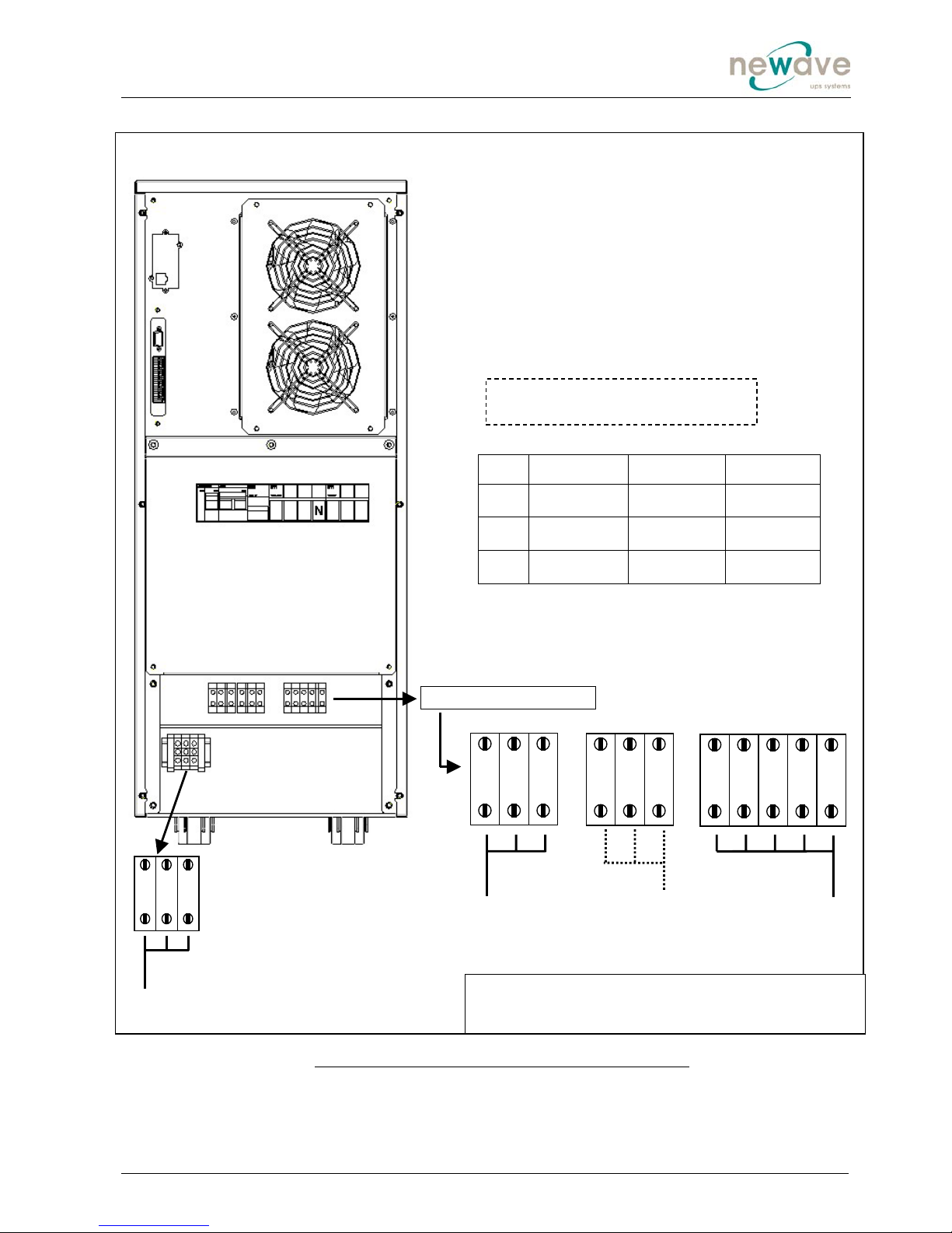
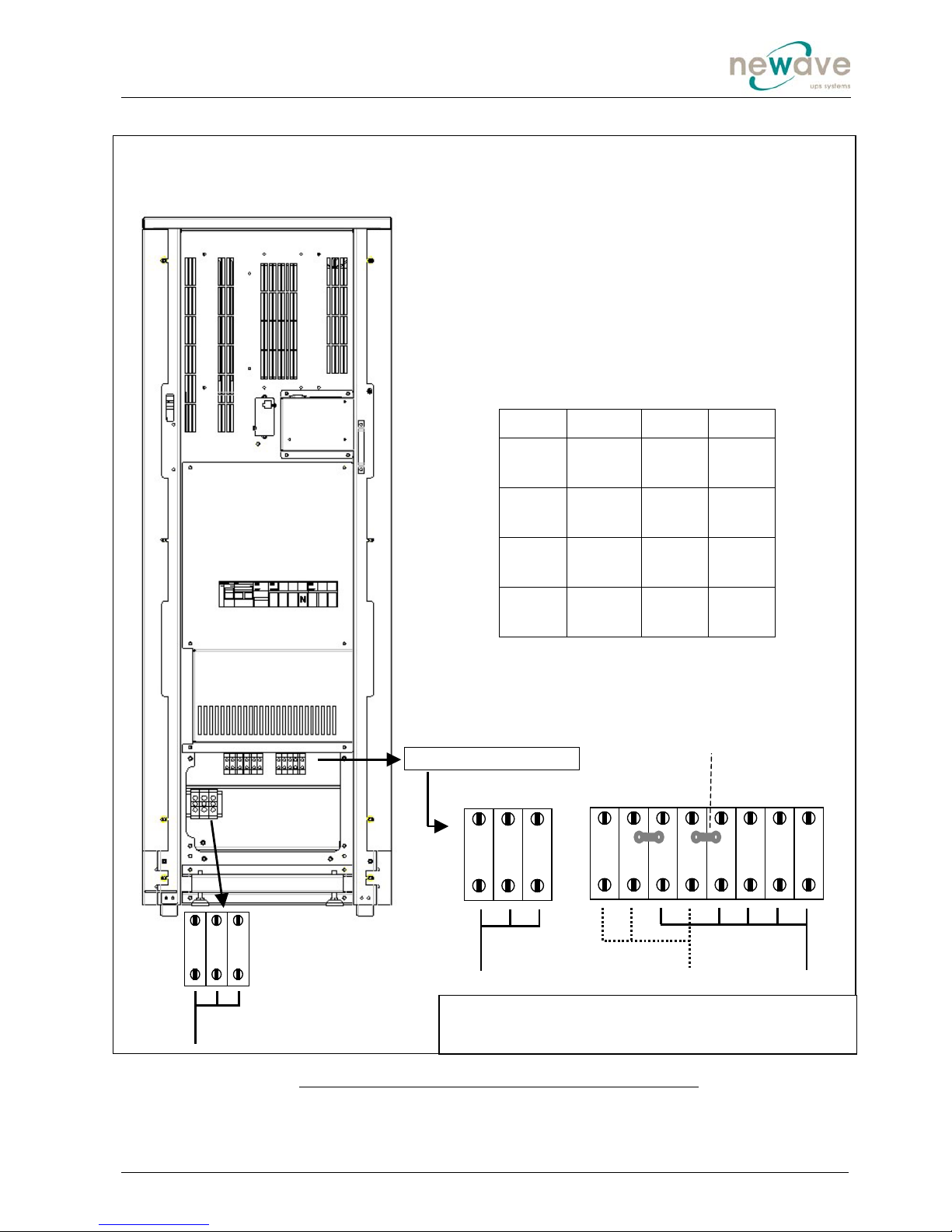
Elements:
FA1 Rectifier Line Fuse
FA2 Bypass Line Fuse
FA3 Battery Fuse
IA1 Maintenance Bypass
IA2 Output Switch
JD1 Smart Port-RS232 (SUB-D9P/F)
X1-X21 Dry Port-volt-free contacts on
terminal block (see chapter 3.8.2)
In/Out Terminal Block
+ N -
Only for
external
battery
FA1
IA1 IA2 FA2 FA3
X1-X21
JD1
SNMP
FA1 (A) FA2 (A) FA3 (A)
7,5kVA 50 A
(14x51)
ultrafast
50 A
(14x51)
GL/GC
32 A
(10x38)
ultrafast
10kVA 50 A
(14x51)
ultrafast
50 A
(14x51)
GL/GC
32 A
(10x38)
ultrafast
12kVA 50 A
(14x51)
ultrafast
50 A
(14x51)
GL/GC
32 A
(10x38)
ultrafast
Figure 1 Connection of UPS POWERVALUE 7.5, 10 and 12kVA with single phase input mains supply. Output
Load connection terminals and connection of possible optional battery cabinet (SINGLE INPUT FEED).
PowerValue
TM
11
Cabinet “A” rear View / Cabinet “B and C ” front View
Output
(To Load)
3L1 3N PE
Mains Input
(Single Feed)
1N 1L1 PE
Separate Bypass
(For Dual Feed)
PE 2L1 2N
Cabinet A
Cabinet B and C
SNMP
JD1 X1-
X21
FA1
IA1 IA2 FA2 FA3
Note: the number of fans depend on
the power of the UPS.

Newave_OPM_PV11_PV31 _GB_250805.doc Installation Page 14
3.6.12 Cabling of POWERVALUE 7.5, 10, 12, 15 and 20kVA with THREE PHASE INPUT
NOTE: Before you start cabling your UPS POWERVALUE make sure you have determined
the correct Version with the right POWER and INPUT CONFIGURATION.
NOTE: THIS UPS COMES (STANDARD VERSION) WITH A SINGLE CABLE FEED (FOR
RECTIFIER AND BYPASS). IF DUAL FEED IS REQUESTED PLEASE CONTACT YOUR
SERVICE OFFICE BEFORE PERFORMING ANY CABLING OF UPS.
3.6.13 Connection Diagram
To ensure correct operation of the UPS and its ancillary equipment it is necessary to provide the mains
cables with appropriate fuse protection.
To connect the PowerValueTM to the mains power supply see Figures 2 and 3.
ALL THE OPERATIONS IN THIS MANUAL MUST BE PERFORMED BY AUTHORISED
ELECTRICIANS OR BY QUALIFIED INTERNAL PERSONNEL.
DO NOT OPERATE IN CASE OF PRESENCE OF WATER OR MOISTURE.
BY OPENING OR REMOVING THE UPS-COVERS YOU RUN RISK OF EXPOSURE TO
DANGEROUS VOLTAGES!
3.6.14 Preparation for the Three Phase Input Cabling
Before you start connecting the UPS, ensure that:
• MAINS VOLTAGE (INPUT VOLTS) AND FREQUENCY (FREQUENCY) CORRESPOND
TO THE VALUES INDICATED ON THE NAMEPLATE OF THE UPS.
• EARTHING IS PERFORMED IN ACCORDANCE WITH THE PRESCRIBED IEC
STANDARDS OR WITH LOCAL REGULATIONS;
• UPS IS CONNECTED TO THE MAINS THROUGH A LV-DISTRIBUTION BOARD WITH A
SEPARATE MAINS LINE (PROTECTED WITH A CIRCUIT BREAKER OR FUSE) FOR
THE UPS.
Provide input breaker and cables according to the indications in TECHNICAL SPECIFICATIONS at the
end of this USER MANUAL or in accordance with the prescribed IEC Standards or in accordance with
the local regulations.
The input of the UPS must be fitted with circuit breakers or other kind of protection. The circuit
breakers will be connected between the mains supply and the UPS and will provide additional
protection to the UPS in the event of overloads and short circuits.
3.6.15 Earthing
ALL THE OPERATIONS IN THIS MANUAL MUST BE PERFORMED BY AUTHORISED
ELECTRICIANS OR BY QUALIFIED INTERNAL PERSONNEL.
To ensure protection of personnel during the installation of UPS make sure that the connections are
performed under the following conditions:
• No mains voltage is present;
• Loads are shut down and disconnected;
• UPS PowerValueTM is shut down and voltage-free.
Maintenance Bypass (MANUAL BYPASS) is open in position OFF
1) Unscrew both screws of the terminal cover plate (4) and remove the terminal cover plate.
2) Carefully remove terminal cover plate (4) and don’t pull on the earthing wire (5). If necessary the
earthing wire may be removed during the cabling. When the cabling has been performed the earthing
wire must be connected again.
3) Connect the earthing wire coming from the LV-Distribution Board to the terminal "PE".
!
!

Newave_OPM_PV11_PV31 _GB_250805.doc Installation Page 15
Under the connection terminal of the UPS there is a cable-fixing rail to ensure that the cables have
been fastened properly
3.6.16 Connection of the Mains Supply
After the UPS has been unpacked and brought to its final position the authorized technician may start
with the cabling.
ALL THE OPERATIONS IN THIS MANUAL MUST BE PERFORMED BY AUTHORISED
ELECTRICIANS OR BY QUALIFIED INTERNAL PERSONNEL.
To ensure protection of the personnel during the installation of the UPS make sure that the
connections are performed under the following conditions:
• No mains voltage is present;
• All loads are shut down and disconnected;
• UPS PowerValueTM is shut down and voltage-free.
Remove the terminal cover of the UPS
Before connecting the input power cables make sure that:
• UPS-System is placed in its correct position;
• Maintenance Bypass IA1 is open in position OFF;
Connect the input power cable coming from the LV-Distribution Board to the terminals of the UPS in
accordance with Figures 2 and 3.
NOTE: Neutral input wire must always be connected!
NOTE: The UPS PowerValueTM is provided with facilities for both single feed (one common input
cable for rectifier and bypass) and dual feed (two separate input cables for rectifier and bypass
respectively).
The standard UPS PowerValueTM is always supplied with facilities for a single feed. If dual feed
is required please contact next Service Centre.
3.6.17 Single Input Feed
To achieve correct Input Cabling see Drawing in see Figures 3.
For single input feed connect the mains input cable to UPS Terminal Block according to the following
table:
For minimum recommended Input Cable Sections and Fuse Ratings for the PowerValueTM see table in
Section Technical Specifications at the end of this User Manual.
Under the connection terminal of the UPS there is a cable-fixing rail to ensure that the cables have
been fastened properly.
3.6.18 Dual Input Feed
NOTE:In the standard version PowerValueTM comes with SINGLE INPUT FEED. If DUAL
INPUT FEED is required please contact your next service office before performing any cabling.
MAINS INPUT CABLE UPS TERMINAL
Phase L1 1L1
Phase L2 1L2
Phase L3 1L3
NEUTRAL 1N
EARTH PE
!
!

Newave_OPM_PV11_PV31 _GB_250805.doc Installation Page 16
3.6.19 Preparation for the Output Cabling3
Before you start connecting the loads, ensure that the sum of the indicated UPS-Systems rated
powers (OUTPUT POWER) on the nameplates (on the front side of the UPS-Systems) is equal to or
larger than the total load requirements.
The output of the UPS must be fitted with circuit breakers or other kind of protection. These circuit
breakers will be connected between the loads and the UPS and will provide additional protection to the
UPS in the event of overloads and short circuits.
These circuit breakers will enable the protection of each load separately.
The size of the circuit breakers depends on the load rating of the load sockets.
The circuit breakers must comply with the prescribed IEC Standards. It is recommended to provide a
separate output distribution board for the load.
• The following values should be indicated on the output distribution board:
• Maximum total load rating;
• Maximum load rating of the load sockets.
• If a common distribution board is used (sockets for Mains and UPS voltage), ensure that on
each socket there is an indication of the applied voltage (“Mains” or “UPS”).
Output power cable ratings should be in accordance with the recommended cable sections and fuses
ratings or in accordance with the prescribed IEC Standards or with the local regulations.
Under the connection terminal of the UPS there is a cable-fixing rail to ensure that the cables have
been fastened properly.
Ensure that the earthing is performed in accordance with the prescribed IEC Standards or with the
local regulations.
3.6.20 Connection of the Load
ALL THE OPERATIONS IN THIS MANUAL MUST BE PERFORMED BY AUTHORISED
ELECTRICIANS OR BY QUALIFIED INTERNAL PERSONNEL.
To ensure protection of the personnel during the installation of the UPS make sure that the
connections are performed under the following conditions:
• No mains voltage is present;
• All loads are shut down and disconnected;
• UPS PowerValueTM is shut down and voltage-free.
Before connecting the output power cables make sure that:
• UPS-Systems is fitted in its correct position;
• Maintenance bypass is in position OFF;
Remove the terminal cover of the UPS.
Connect the output power cable coming from the LV-Distribution Board to the terminals of the UPS as
shown in drawing in Figure 3.
!

Newave_OPM_PV11_PV31 _GB_250805.doc Installation Page 17
3.6.21 Output Cabling
To achieve correct Output Cabling see Terminal Block in Figure 3.
For output cabling connect output cable to UPS Terminal according to following Output to UPS
terminal block correlation.
OUTPUT CABLE UPS TERMINAL
Phase L1 3L1
NEUTRAL 3N
EARTH PE
Under the connection terminal of the UPS there is a cable-fixing rail to ensure that the cables have
been fastened properly
3.6.22 How to fix the POWERVALUE to the floor
After having performed the connections screw the terminal cover plate back on the UPS.
Make sure that the earthing wire is correctly connected on the terminal cover plate.
Once the UPS has been brought to its final position it should be blocked by means of the 2 castors
which are situated near the two front rollers of the UPS.
Newave_OPM_PV11_PV31 _GB_250805.doc Installation Page 18
FA1 (A) FA2 (A) FA3 (A)
7,5kVA 32 A (10x38)
ultrafast
50 A (14x51)
GL/GC
32 A (10x38)
ultrafast
10kVA 32 A (10x38)
ultrafast
50 A (14x51)
GL/GC
32 A (10x38)
ultrafast
15kVA 32 A (10x38)
ultrafast
80 A (22x58)
GL/GC
50 A (14x51)
ultrafast
PowerValue
TM
31
Cabinet “A” rear view
Mains Input
(Single Feed)
Separate Bypass
(For Dual Feed)
Output
(To Load)
3L1 3N PE PE 2L1 2N
Cabinet A
Elements:
FA1 Rectifier Line Fuse
FA2 Bypass Line Fuse
FA3 Battery Fuse
IA1 Maintenance Bypass
IA2 Output Switch
JD1 Smart Port-RS232 (SUB-D9P/F)
X1-X21 Dry Port-volt-free contacts on terminal block
(see chapter 3.8.2)
1N 1L1 1L2 PE1L3
Figure 2 Connection of UPS POWERVALUE 7.5,10 and 15 kVA with three phase input mains supply. Output
Load connection terminals (SINGLE INPUT FEED).
IA1 IA2 FA2 FA1 FA3
In/Out Terminal Block
+ N -
Only for
external
battery
X1-X21
JD1
SNMP
Note: the number of fans depend on
the power of the UPS.
Newave_OPM_PV11_PV31 _GB_250805.doc Installation Page 19
FA1 (A) FA2 (A) FA3 (A)
7,5kVA 32 A
(10x38)
ultrafast
50 A
(14x51)
GL/GC
30 A
(10x38)
ultrafast
10kVA 32 A
(10x38)
ultrafast
50 A
(14x51)
GL/GC
30 A
(10x38)
ultrafast
15kVA 32 A
(14x51)
ultrafast
80 A
(22x58)
GL/GC
50 A
(14x51)
ultrafast
20kVA 32 A
(10x38)
ultrafast
100 A
(22x58)
GL/GC
50 A
(10x38)
ultrafast
Mains Input
(Single Feed)
Remove Link between 2L1
and 1L1for Dual Feed
Separate Bypass
(For Dual Feed)
Output
(To Load)
2L1 1L1 1L2 1L3 PE
3L1 3N PE PE 2N 1N
Cabinet B and C Elements:
FA1 Rectifier Line Fuse
FA2 Bypass Line Fuse
FA3 Battery Fuse
IA1 Maintenance Bypass
IA2 Output Switch
JD1 Smart Port-RS232 (SUB-D9P/F)
X1-X21 Dry Port-volt-free contacts on terminal
block (see chapter 3.8.2)
PowerValue
TM
31
Cabinet B and C, front view
Figure 3 Connection of UPS POWERVALUE 7.5, 10, 15 and 20kVA with three phase input mains supply. Output
Load connection terminals (SINGLE INPUT FEED).
In/Out Terminal Block
+ N -
Only for external
battery
SNMP
JD1 X1-
X21
FA1
IA1 IA2 FA2 FA3

Newave_OPM_PV11_PV31 _GB_250805.doc Installation Page 20
3.7 CONNECTION OF EXTERNAL BATTERIES FOR UPS POWERVALUE
For the standard POWERVALUE products no external battery cabinets are provided. Longer
autonomies are achieved by using one of the higher UPS Cabinets B or C which have more space for
batteries than the Cabinet A.
The PowerValueTM UPS is delivered with an optional external batteries connection terminals only if it
has been ordered without batteries.
THE CONNECTION OF THE EXTERNAL BATTERIES MUST BE PERFORMED BY AUTHORISED
ELECTRICIANS OR BY QUALIFIED INTERNAL PERSONNEL.
To connect external batteries :
SNMP
X1-X21
JD1
In/Output Terminal Block
IA1 IA2 FA2 FA1 FA3
+ N -
External
battery
Internal
battery
1. Disconnect the wires for internal
battery at the bottom of FA3 (red).
2. Connect the wires from external
battery terminals at the bottom of FA3
(green).
3. Connect the wires from the external
battery cabinet to the UPS.
12
3
This manual suits for next models
1
Table of contents
Other Newave UPS manuals


