Newave 1000-3000VA User manual

UserManual
1000-3000VA(singlephaseIn/Output)
IntelligentTrueOn-LineUninterruptiblePowerSupply(UPS)
ForCorporate& ITUserInstallationGuide
IntelligentTrueOn-LineUninterruptiblePowerSupply(UPS)
ForCorporate& ITUserInstallationGuide

TABLEOFCONTENTS
1StandardUnitInstallationGuide4
1.1Important– Pleasereadcarefullypriortoinstallation4
1.2StorageInstruction4
2ProductIntroduction5
2.1GeneralCharacteristics5
2.2SpecialFeatures5
3UPSFunctionalDescriptions6
3.1UPSFrontPanelDisplayDescriptions6
3.2RealPanelDescriptions7
3.3OperatingModes& VoltageSystemConfigurations8
3.3.1SystemConfigurationSettings8
3.3.2Programmableoutletsetting9
4InstallationandOperation10
4.1Unpacking10
4.2SelectingInstallationPosition11
4.3TowerConfigurationSetup12
4.4Rack-MountConfigurationSetup14
4.5Operation16
4.5.1StartUpinNormalACMode16
4.5.2Start-upinBatteryMode(ColdStart)16
4.5.3Shutdown16
4.5.4SelfTestingduringACmode17
4.5.5Status& AlarmBuzzer17
4.5.6BatteryReplacement18
5UPSWorkingPrinciple20
5.1UPSSystemBlockDiagram20
5.2WhenUtilityisNormal21
5.3WhenUtilityisAbnormal/Absent21
5.4OverloadCondition22
5.5InverterFailure23
5.6Inverter/InternalOvertemperature23
5.7InverterOver-currentandInverterOutputVoltageOutoftolerance23
6MaintenanceGuide24
6.1TroubleShooting24
6.2ErrorCodesandTheirDescriptions26
7BundleSoftwareInstallationGuide26
7.1HardwareInstallation26
7.2WAVEMONShutdownandManagementSoftware27
7.2.1WhyisUPSManagementimportant?27
7.2.2WavemonShutdownandMonitoringSoftware27
7.3SNMPCARD/ADAPTERForNetworkManagement/RemoteMonitoring29
8CommunicationPortExplanation30
8.1TrueRS232PortDescriptions30
8.1.1USBPortDescriptions31
8.2ThePinassignmentsoftheEPOInputportare:31
9OptionalCommunicationCards31
9.1AS400(DryContact)card31
9.2SNMPCards32
10BatteryBankInstallation33
10.1Chapter1:ImportantSafetyInstructions33
10.2Chapter2:IntroductiontotheFrontandRearPanel34
10.2.1FrontandRearPanelDescriptions34

10.3Chapter3:InstallationandOperation35
10.3.1Unpacking35
10.3.2SelectingInstallationPosition36
10.3.3InstallationInstructions37
10.3.4RackMountinstallation39
10.3.5StorageInstruction42
10.3.6ReplacingtheBattery42
10.3.7Specifications43
10.3.8RecyclingtheUsedbattery44
11TechnicalSpecifications45

1StandardUnitInstallationGuide
1.1Important– Pleasereadcarefully priortoinstallation
1.ThoughthisUPSisdesignedforeasyPlug-and-Playinstallation,itisadvisabletoengage
qualifiedElectricalEngineerortrainedtechnicalpersonneltocommissionorrepairtheUPS.
2.ThisUPSisequippedwithanEMIfilter.Topreventpotentialleakagecurrenthazard,ensurethat
theACmainsupplyissecurelygrounded.
3.TopreventanyoverheatingoftheUPS,keepallventilationopeningsfreefromobstruction,and
donotplaceanythingontopoftheUPS.KeeptheUPSrearpanel30cmawayfromthewallor
otherobstructions.
4.ThisUPSisdesignedtobeinstalledandcommissionedina sheltered,controlledenvironmentas
follows:
-Operatingtemperature0-40°Cand30-90%non-condensinghumidity
-Alwaysavoidcontactwithdirectsunlight
5.TheUPSinternalbatteryshouldberechargedevery2-3monthsifnotinusetopreventbattery
self-discharge.ThebatterycanberechargedwhentheUPSisconnectedtotheutilitysupplì.
6.AlwaysswitchofftheUPSanddisconnectthebatterieswhenrelocatingtheUPS.
7.PleaseensurethattheinputvoltageoftheUPSmatchestheutilitysupplyvoltage.Usea certified
inputpowercablewiththecorrectplugsandsocketsfortheappropriatevoltagesystem.
8.CAUTION-TheWarrantyoftheUPSwillberenderedvoidandthemanufacturerreservesthe
righttorefusereplacement/compensationunderthefollowingconditions:
-AccidentaldamagetotheUPS
-InstallingtheUPSininflammableorhazardousenvironment.
-Improperinstallationormaintenancebyunauthorisedpersonnel
1.2StorageInstruction
Forextendedstorageinmoderateclimate,thebatteriesshouldbechargedfor12hoursevery3
monthsintervalbyconnectingtheUPStotheutility supplyandswitchoninputbreakerlocatedat
UPSrearpanel.Repeatthisprocedureevery2 monthsifthestorageambienttemperatureisabove
30°C.

2Product Introduction
2.1GeneralCharacteristics
1.Trueonlinetechnologycontinuouslysuppliesyourcriticaldevicewitha stable,regulated,
transient-freepuresinewaveACPower.
2.High-efficiencyPWMsine-wavetopologyyieldsanexcellentoverallperformance.Thehighcrest
factoroftheinverterhandlesallhighin-rushcurrentloadswithouttheneedtoupgradethepower
rating.
3.User-friendlyPlug-and-Playdesignallowshassle-freeinstallation.Allunitsupto3Kvaare
suppliedwithinputcablesandoutputsocketsasstandard.
4.Built-inMaintenance-freesealed-typebatteryminimisestheneedforfrequentafter-salesservice.
5.Toprotecttheunitfromoverloading,theUPSwillautomaticallyswitchtobypassmodein30
secondsifloadingisat105%~120%ofratedcapacity.Itwillautomatically switchbacktoinverter
modeonceoverloadconditionceases.
6.Shouldtheoutput becomesshort-circuited,theUPSputsthesystemonstand-bymode,provide
visual& audiblealarm,andcutstheoutputsupplyautomaticallytilltheshortcircuitsituationis
resolvedmanually.
2.2SpecialFeatures
1.HighFrequencyTransformer-lesstechnologywithrack/towerconvertibleenclosureenablesthe
UPSforintegrationeveninthemostdifficultofenvironmentwithspaceconstraints.
2.ThisUPSisequippedwithfullydigitalizedcontrollogicforgreaterfunctionalityandenhanced
highlevelofpowerprotection.Digitalsignalprocessing(DSP)alsoprovidestheUPSwith
powerfulcommunicationcapability,whichenhancestheflexibilityforeasyremotecontroland
monitoring
3.Wideinputvoltagetolerancefrom120V~288V(220Vversion)allowsunder-voltageorover-
voltagecorrectionwithoutunnecessarybatterydrainandhelpsextendthebatterylifespan.
4.DC-startfunctionensuresthestart-upofUPSevenduringpoweroutages.
5.Revolutionarybatterymanagementcircuitanalyzesbatterydischargingstatustoadjustbattery
cut-offpointandextendthebatteries’lifespan.
6.ActivePowerFactorCorrection(PFC)controlfunctionconstantlymaintainstheUPSInputPower
Factor(PF)at> 0.99forsuperbenergyefficiency.
7.SelectableBypassinputvoltagetolerance(Sensitivitylow/high)topreventunderorovervoltage
beingsupplytotheloadsatBypassmode.TheselectableVoltagerangesare(i)SensitivityLow:
184~260V& (ii)SensitivityHigh: 194~260V.
8.VastSelectableOutputVoltages(200/208/220/230/240)tomeetvariousvoltagesystems.
9.TheUPSisdesignedtocomplywithvariousstringentinternationalstandardsforElectromagnetic
Interference& protection(EMC).
3UPSFunctionalDescriptions
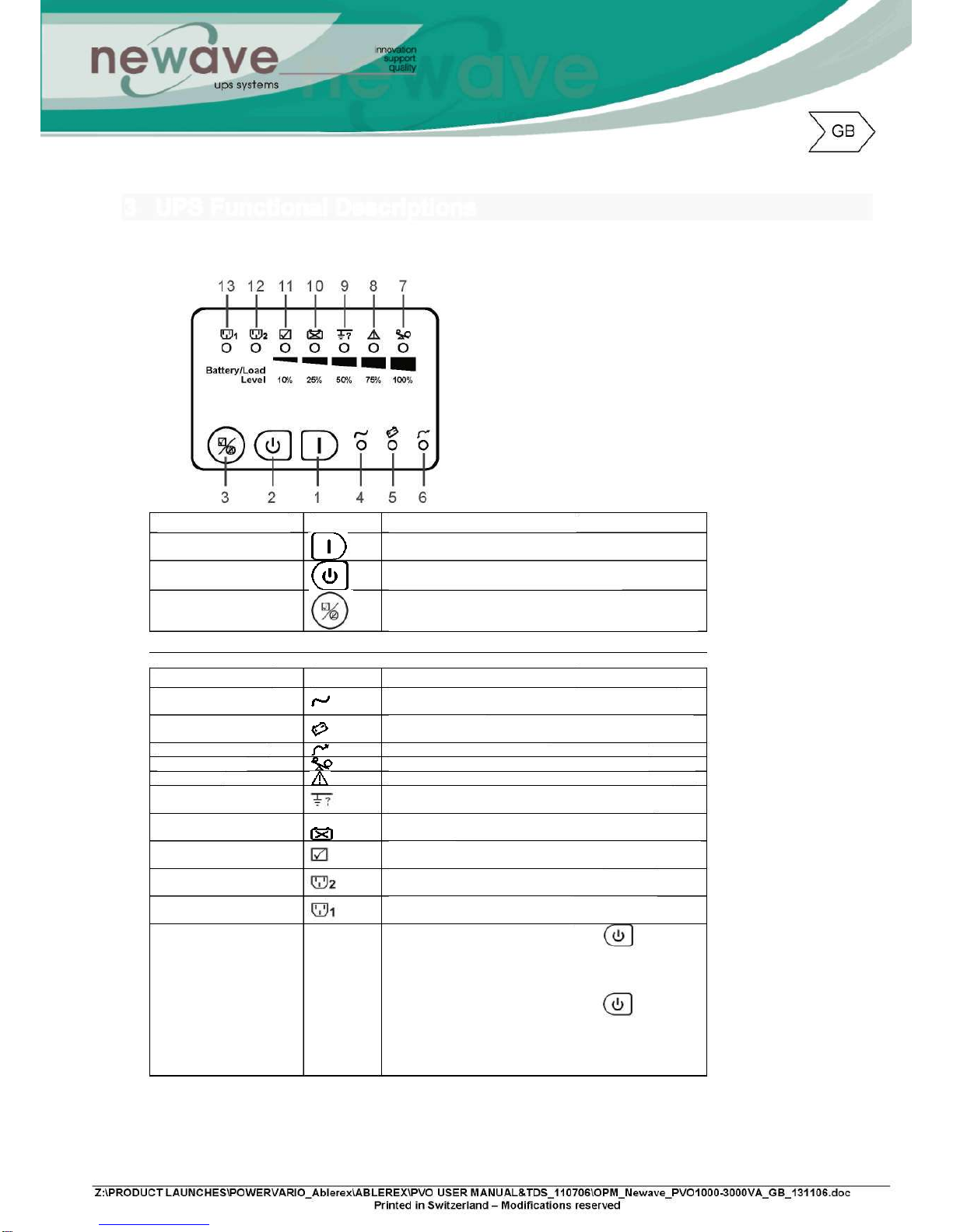
3.1UPSFrontPanelDisplayDescriptions
ControlKeypads Symbols FunctionalDescriptions
1.
ON UPSPower-OnSwitch
2.OFF UPSPower-OffSwitch
3.Self-Test(AlarmSilence) a.CommandtheUPStoperformself-testing
b.AlarmSilence-
Tomutethealarmbuzzer(Donotpress& holdfor> 1 sec)
LEDIndicators Symbols FunctionalDescriptions
4.NormalModeLED LEDilluminatedindicatesutilityvoltagewithintolerance
(120Vac~280Vac)
5.BatteryModeLED LEDilluminatedindicatesutilityoutageoroutoftolerance,
loadssupplybybatterypower
6.BypassModeLED LEDilluminatedindicatesbypasssupplyisnormal
7.OverloadLED RedLEDilluminatedindicatesUPSisoverloaded
8.FaultLED RedLEDilluminatedindicatesfaultorabnormalconditions
9.SitewiringfaultLED RedLEDilluminatedindicatesLive& Neutrallinesare
connectedwronglyorHighNeutral-Groundvoltage
10.BatteryBad/WeakLED RedLEDilluminatedindicateslowbatterypowerorfaulty
batterybank
11.SelfTestLED GreenLEDilluminatedindicatessuccessfulself-testandno
abnormalconditionsor faultswerefound
12.Outlet2LED GreenLEDilluminatedindicatesUPSOutlets2 are
enabledandreadytosupplyloads
13.Outlet1LED
GreenLEDilluminatedindicatesUPSOutlets1 are
enabledandreadytosupplyloads
711LEDs(%Indicating
Bars)
a.DuringNormalMode: Pressandholdfor1 sec,
the7~11LEDswillfunctionasLoadRateindicators
showing100%,75%,50%,25%or10%ofUPScapacity
used.TheseLEDswillstopilluminatingafter10sec.
b.DuringBatteryMode: Pressandholdfor1
sec> the7~11LEDswillfunctionasBatteryPower
indicatorsshowing100%,75%,50%,25%or10%Battery
Powerremaining.TheseLEDswillstopilluminatingafter10
sec.
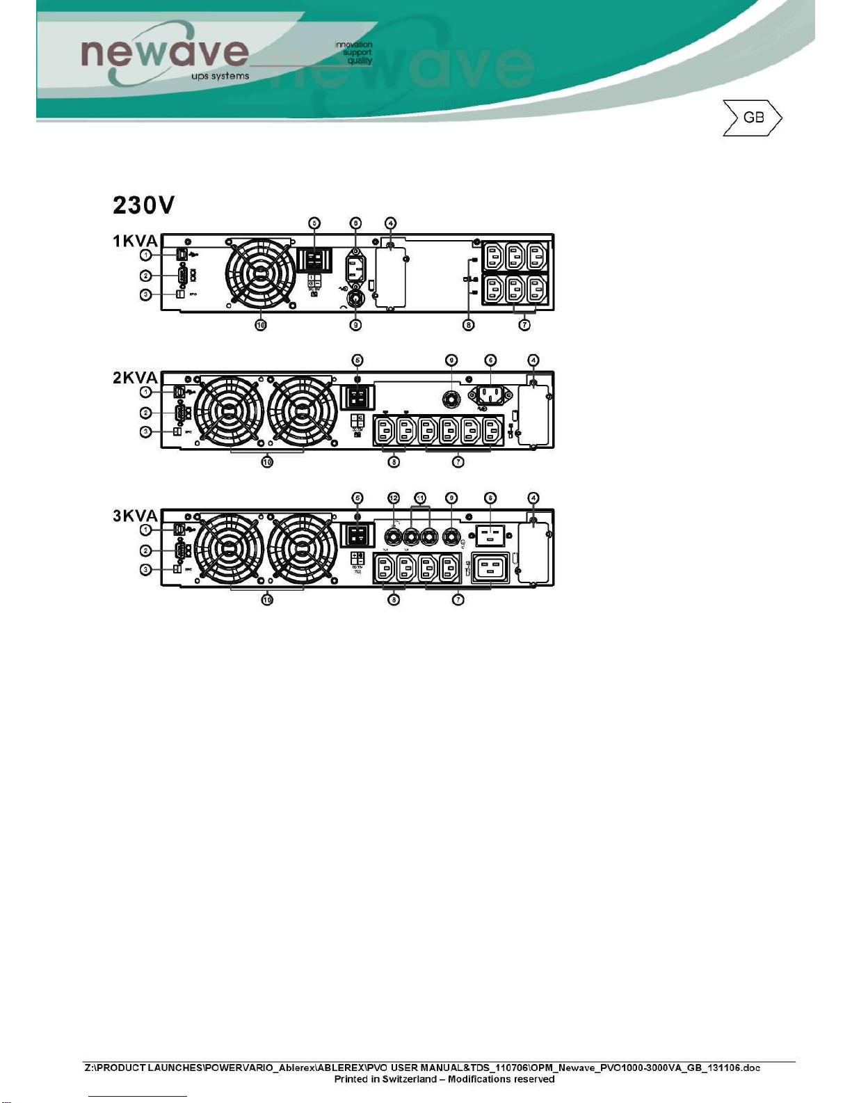
3.2RealPanelDescriptions
1.USBPort
2.RS232Port
3.EmergencyPowerOff(EPO)DryContactSignalinputs
4.CommunicationCardOptionsSlot
5.ExternalBatteryConnector
6.ACpowerconnectionsocket
7.ACOutlets
8.Twoprogrammableoutlets
9.UtilityInputfuseholder
10.CoolingFans
11.Output
fuseholders
12.Outputfuseholdersfortwoprogrammableoutlets

3.3OperatingModes& VoltageSystemConfigurations
Throughthesoftwarethatisdeliveredwiththeunityoucanregulatetheoutputvoltageandthe
powersocket
3.3.1SystemConfigurationSettings
1.System:SelectInputVoltage220V
2.Vo:SelectUPSOutputVoltage
200V/208V/220V/230V/240V/250V
3.UPSModes: SelectNormal/CF50*/CF60*Mode
4.Fineturningof:OutputVoltageRegulationfrom0 ±3%
5.BypassSensitivity:SelectSensitivityLow/SensitivityHigh**
6.Synchronizing:Select3Hz/1HzInverterFreqsynchronizingrange
7.KVA:Keyin1 or2 or3 fortheUPSKVArating
8.ComPort:SelectComPorttoPC
9.Clickon“Write”toconfirmtheconfigurationsettings.TheUPSwillsound2 “beeps”to
acknowledgesettingissuccessful.
Note:*CF50/CF60= FrequencyConvertermode50to60Hzorviceversa
**SensitivityLow: 184~260V,High:194~260V
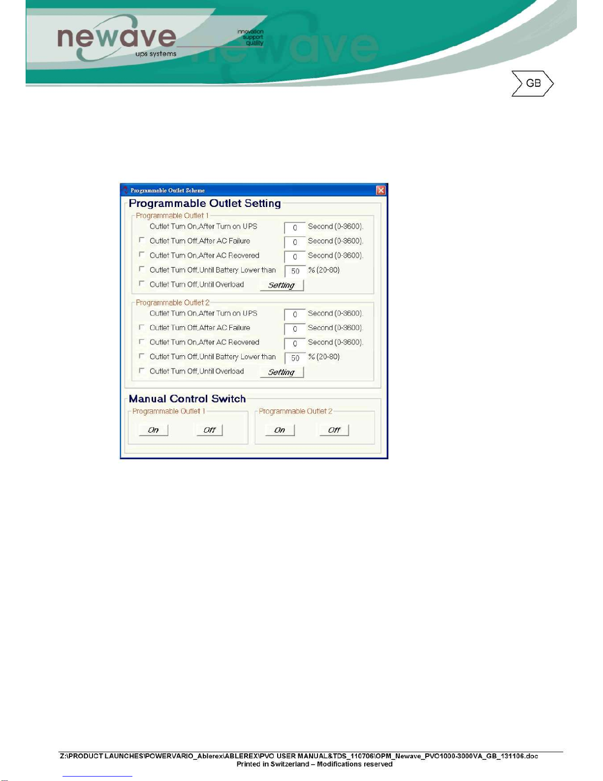
3.3.2Programmableoutletsetting
TheUPSisequippedwith2 programmableoutletsforusetosupplytolesscriticalloads.These
outletscanbedisabledtoshedthelesscriticalloadsduringback-upmodesoroverload
conditionstomaintainqualitypowersupplytothemorecriticalloadsconnectedtotheUPS.
Clickonthe“Programmableoutletsetting”bartoentertothesettingscreenasshownbelow.
1.OutletTurnOnAfterTurnonUPS– selectthetimetoautomaticallyenablethisoutletwithinthe
specifiedtimewhentheUPSispoweron.If“0”secisselected,theoutletwillbeenabledonce
theUPSispoweron.
2.OutletTurnOffAfterACFailure– selectthisoptiontoautomaticallydisabletheoutletwithinthe
specifiedtimeafterutility outagetoshedthelesscriticalloadstoprovidelongerbatteryback-up
timefortheothermorecriticalloadsconnectedtotheUPS.
3.OutletTurnOnAfterACRecovered– selectthisoptiontoautomatically enabletheoutletwithin
thespecifiedtimeaftertheutilityisrestored.
4.OutletTurnOffWhenBatteryLowerthan- selectthisoptiontoautomaticallydisabletheoutlet
atthespecifiedremainingbatterypowercapacity(%)duringbatterymodetoshedtheless
criticalloadstoprolongbatteryback-uptimefortheothermorecriticalloadsconnectedtothe
UPS.
5.OutletTurnOffWhenOverload– selectthisoptiontoautomatically disabletheoutletduring
overloadcondition(bypassmode)topossiblyallowthemorecriticalloads:
a)TobecontinuallysuppliedviaBypasswithoutshutdown
b)TobetransferredbacktoInvertermodeiftheoverloadconditionisremovedbyshedding
thelesscriticalloads.
6.Clickon“setting”toconfirmtheconfigurations.TheUPSwillsound2 “beeps”toacknowledge
settingissuccessful.
7.ManualControlSwitch– Click“On”or“Off”tomanuallyenabledordisabledtheprogrammable
outlets,overridingallprevioussettings.

4InstallationandOperation
ReadtheSafetyInstructionguide(page2 to3)beforeinstallingtheUPS
4.1Unpacking
InspecttheUPSuponreceipt.Themanufacturerdesignedrobustpackagingforyourproduct.
However,accidentsanddamagemayoccurduringshipment.Notifytheforwarderanddealerifthere
isdamage.
Thepackagingis recyclable;saveit forreuseor disposeof it properly.
RemovetheUPSfromthecartonbox.
Checkthepackagecontents.Standardcontentshallincludes:
1setofUser'sManual
2pcsofIECoutputcables(forUPSwithIECsocketsonly)
1pcofACInputPowerCord
1setofUPScommunicationsoftwarewithRS232cable
1setofTower/RackAccessoriesKitasbelow:
Optiona
l
Optiona
l
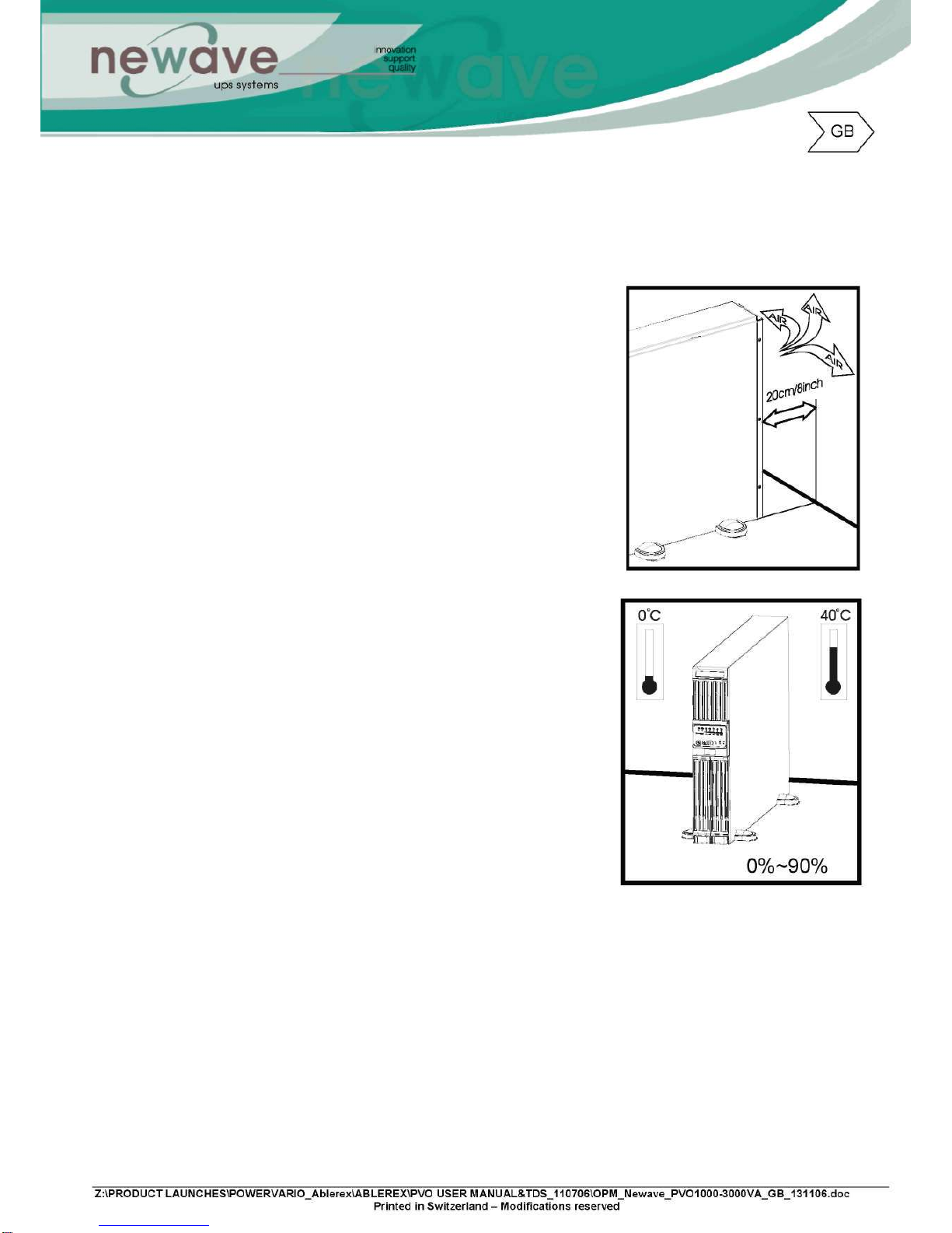
4.2SelectingInstallationPosition
TheUPSisheavy.Selecta locationsturdyenoughtohandletheUPSweight.
Toensureproperoperationandlongoperatinglife,alwayspositiontheUPSaccordingtothe
followingrequirement:
1.Keepminimum20cm(8inches)distanceclearancefrom
therearpaneloftheUPStoavoidanyobstructions.
2.Donotblocktheair-flowtotheventilationlouversofthe
unit.
3.Pleaseensuretheinstallationsiteisfreefromexcessive
dustandtheambienttemperatureandhumidityshouldbe
withinthespecifiedlimits.
4.DonotplacetheUPSina dustyorcorrosiveenvironment
ornearanyflammableobjects.
5.ThisUPSisnotdesignedforoutdooruse.
Relativehumidity
(noncondensation)

4.3 TowerConfigurationSetup
Step1
Step2
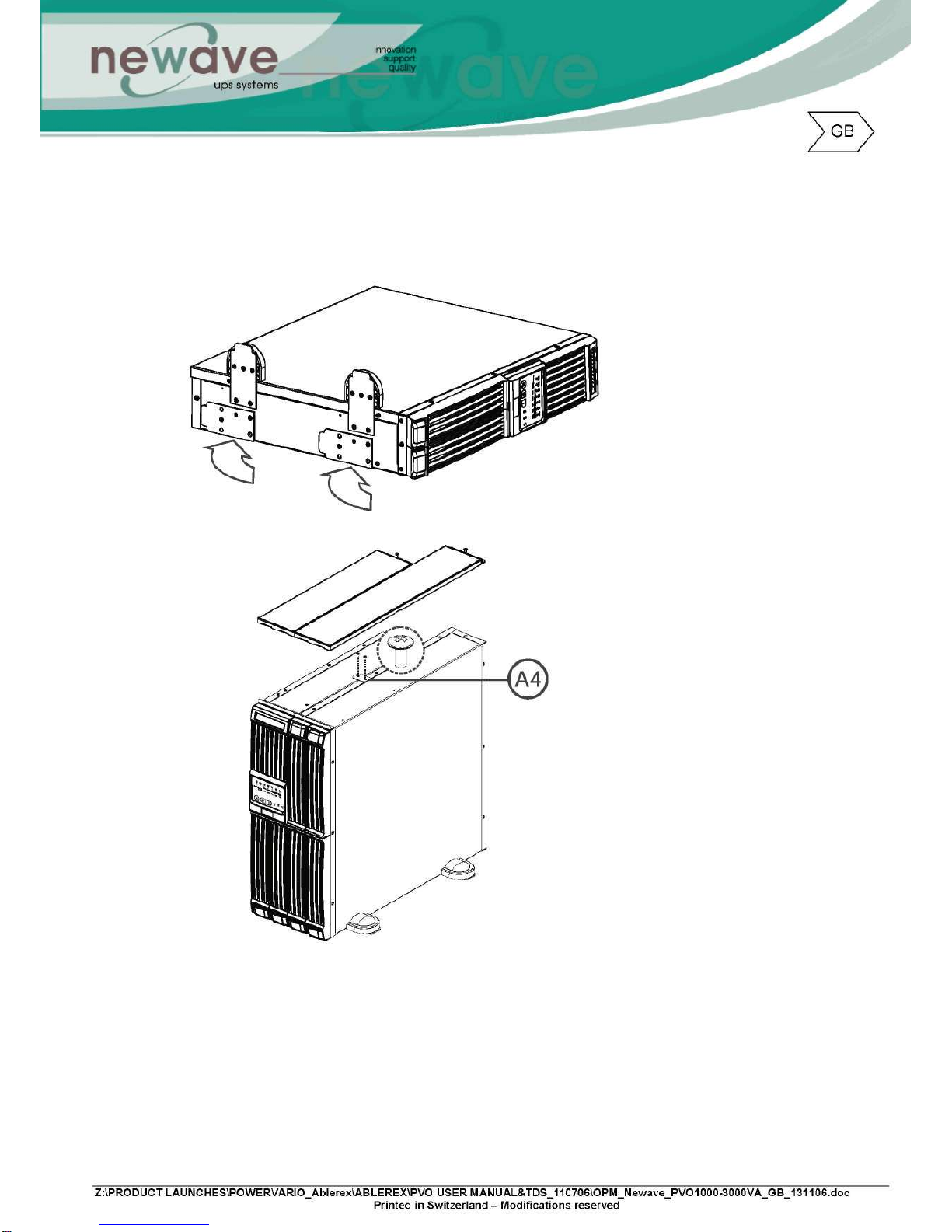
Step3
Step4
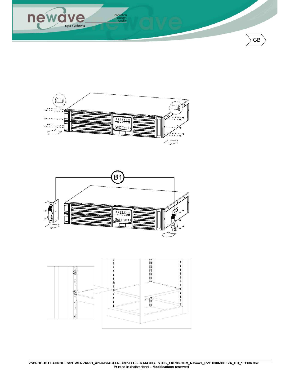
4.4Rack-MountConfigurationSetup
Step3
Step4
Step5

Step6
Step7
4.5Operation
4.5.1StartUpinNormalACMode
1.Beforecommencingtheinstallation,pleaseensurethegroundingisconnectedproperly.
2.EnsurethevoltageofUtilitymatcheswiththeinputvoltagewindowoftheUPS.
3.ConnectUPSmainpowercordintoUtilityACpowersourcereceptacle.
4.SwitchontheACpowersource,alltheLEDsonthefrontpaneldisplaywillflashonceafter3
seconds,exceptwhichwillremainilluminated(Green).Atthesametime,thefanat
therearoftheUPSwillstartoperating.
5.PresstheSwitchforapproximately3 secondstostarttheUPS,thebuzzerwillbeepand
theLEDdisplayofandwilllightupafter30seconds.Thestart-upprocedureis
completedandtheUPSoutletsarereadytosupplytoload.
6.Itisadvisabletoperforma batterymodetestbeforeconnectingtheloadstotheUPStoensure
thebatteriesareworkingproperly.
SwitchOfftheACpowersourcewhentheUPShadbeenswitchedon.TheLEDonthefront
paneldisplaywilllightoffwhiletheLEDwillbeilluminatedandthebuzzeralarmwillbeep
intermediately,indicatingtheUPSisinBatteryMode.
Connecta noncriticalloadtotheUPSoutletstoconfirmiftheBatteryissupplyingpower.
Repeatthetestbyswitchingon& offtheACpowersourcetoensuretheUPSisfunctioning
properly
4.5.2Start-upinBatteryMode(ColdStart)
ThisUPSisabletobeSwitchOnforoperationwithoutthepresenceofanACpowersource.
PressandholdtheSwitchuntilthebuzzerbeep,withinthenext10secpressandholdthe
Switchfortime.TheUPSshallperformitsstart-upprocedure.TheLEDdisplayof
andwilllightupafter30seconds,thebuzzerwillbeepintermediatelytoindicate
successfulpoweron.
Note: Ensure the UPS Battery is pre-charge for minimum 4 hours by simply connecting the AC power cord to the
Utility receptacle.
IftheBatteryVoltageisbelowthepresetvalue(1Kva= 33.5V;2Kva/3Kva= 67V)theUPS
willnotbeabletostartupinBatteryMode.
4.5.3Shutdown
ShutdowninACMode:-
PresstheSwitchforapproximate5 secondsuntilthebuzzerbeeps,theUPSwillstop
powersupplytotheoutlets.LEDsshallremainsilluminatedandtheventilatingfans
shallcontinuetooperate.SwitchOfftheACpowersource,after10sectheLEDswill
lightoffandtheventilatingfansstopoperating.TheUPSisnowcompletelyshutdown.

ShutdowninDCMode:-
PresstheSwitchforapproximate5 secondsuntilthebuzzerbeeps.TheUPSwillstop
powersupplytotheoutlets,LEDslightoffandtheventilatingfansshallstopto
operateafter10sec.TheUPSisnowcompletelyshutdown.
4.5.4SelfTestingduringACmode
AftertheUPShasbeensuccessfullystart-upinACmode,presstheSwitchfor
approximately5 secondsuntilthebuzzerbeeps.TheLEDwillblinktoindicateselftestin
progress.TheLEDwillstopblinkingandremainsilluminatedwhentheselftestiscompleted
withoutfindinganyfaultsorabnormalconditions.TheLEDwillautomatically lightsoff30sec
afterthesuccessfulselftest.
4.5.5Status& AlarmBuzzer
ThefollowingtablehelpstodefinesomeofthecommonUPSstatuses
withrespecttotheirbuzzerbeepdescriptions.
StatusDefinitions BuzzerBeepDescriptions
UPSfaulty,Inverter
shutdown.All
functionsinhabited.
LongContinuousBeep
UPSfaulty,loads
continuetobe
suppliedviaInverter
orBypass.
Singlesuccessivebeepwith~ 2 sec
interval
batterymode Singleshortsuccessivebeepwith~1
secinterval
batterylow Veryquickandshortsuccessive
beep
confirm/RS232port
receiving 2quick& shortbeeps
servicemodeok 1quick& shortbeep
UPSinitialstartsup
withselftest 2successivequick& shortbeeps,
repeatingper~2secinterval.

4.5.6BatteryReplacement
Step1
Step2
Step3

Step4
This manual suits for next models
3
Table of contents
Other Newave UPS manuals


Popular UPS manuals by other brands


Eaton
Eaton Nova AVR 500 Installation and user manual

Integra
Integra EPRO-RACK 1.1KVA user manual

Eaton
Eaton 5E700UD-KR Advanced user's guide

SurgeX
SurgeX SX-DS-154 DEFENDER SERIES MULTIPAK quick start guide

Belkin
Belkin SILVER SERIES F6C350ZSER-SB user manual

Schrack Technik
Schrack Technik GENIO Dual Midi USPRD 1000 VA user manual