Neways Electric MMT01 User manual

Mid-
mounted motor user manual
1
mounted motor user manual
mounted motor user manual

2
Catalogue
1. About the user manual………………………………………………………… 1
2. Motor parameters……………………………………………………………… 2
3. Drive Unit Structure and Dimensions ………………………………………… 4
4. Vehicle schematic diagram………………………………………………… 5
5. List of installation tools…………………………………………………………6
6. Install the meter………………………………………………………………… 7
7. Install auxiliary switch……………………………………………………………8
8. Install speed sensor………………………………………………………………9
9. Install the drive unit………………………………………………………………11
10. System wiring……………………………………………………………………13
11. Install the front chainring………………………………………………………15
12. Install the full-inclusive chain guard……………………………………………15
13. Install half-wrapped chain guard………………………………………………17
14. Install the crank…………………………………………………………………18
15. Change lubricating oil operation…………………………………………………18
16. Overview of instrument functions………………………………………………20
17. Overview of instrument settings……………………………………………… 22
18. The error code of the instrument corresponds to the fault definition…………24
19. Bill of materials………………………………………………………………… 24

1
About User’s Manual
When installing this product, be sure to follow the instructions given in the user's
manual.
Dear users, in order to better assemble the MMT01 mid-mounted motor, please read
the MMTO1 mid-mounted motor operation manual carefully before assembling. We
will tell you every aspect of motor installation in the most concise language to
facilitate your normal use. At the same time, it helps you to solve the confusion and
obstacles that may arise.

2
Motor Parameters
Voltage (DCV) 36V 48V
Rated Power (W) 250W 350W 350W 500W
Rated Voltage
(%)
≧80%
Wheel Size (inch) 20-28
Rated Rotating
Speed
(KM/H)
350W 500W
30±1 35±1
Maximum
Efficiency (Nm)
350W 500W
≧110 ≧130
Chain Wheel 38T(Optional) 42T(Optional) 44T (optional)
Optional Chain
Cover
Half-wrapped chain cover/Full chain cover
Lubricating
Oil
GL-4 75W/90Vehicle gear oil
Weight(KG) 4.6KG
Built-in Sensor Speed assist, torque assist and wheel speed measurement
Noisy (dB) <50
Working
Environment
-30°C-45°C
Dust-proof/ IP66

3
water-proof
grade
Other functions DC6V/100mAFront and rear light modules, programming
function, variable speed sensor module
Drive Unit Structure and Dimensions

Vehicle schematic diagram
4
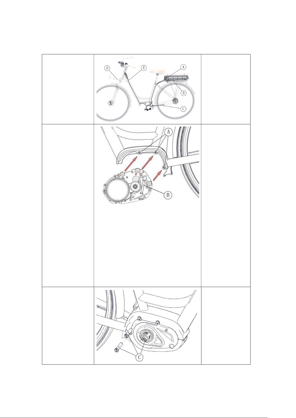
Vehicle schematic diagram

5
A. Drive unit B. Front chain wheel
C.External RPM detecting sensor
D. Display E. Auxiliary keypad

6
List of installation tools
Component utilized location tool
Instrument Fixing screwM4
Allen wrench
Drive
components
Install crankset fixing Bicycle bottom bracket
Chain cover fixing screw
Phillips screwdriver
Connecting the frame and
the drive assembly fixing
Allen wrench
Crank mounting screwM8
Allen wrench
Speed sensor
Magnet installation
Slotted screwdriver
Screw to fix the sensorM5
Allen wrench

Install the meter
According to the diameter
of the tube, the choice is
whether you need a rubber
clamp ring and model
(Applicable to handle
specifications: φ22.2, φ
23.4, φ25.4, Φ31.5),
after the bracket and the
instrument are installed,
the rubber clamp ring is
inserted into the bracket as
shown in the figure position
of the wrist so that the
bracket aligns the notch of
the wrist with the notch of
the rubber clamp ring.
Turn the auxiliary switch on
the wrist and put it on the
handlebar for proper
operation. Adjust the angle
of the auxiliary switch to
make the switch easier to
see and operate when
riding. (Suitable for
handlebars with an outer
diameter of Φ22.2mm.
Use an Allen wrench to fix
and tighten the handlebar
fixing screws in the
direction shown in the
figure.
Locking torque: 1N.m
7
A Rubber clamp ring
model (225,254)
Outer diameter
22.2Choose the
rubber clamp ring
model of the tube:
Left clamp ring
Right clamp
Outer diameter
25.4Choose the
rubber clamp ring
model of the tube:
Left clamp ring
Right clamp
B:
Bracket wrist
C:
Hexagon socket
head screw
A Rubber clamp ring
model (225,254)
Outer diameter
φ
22.2Choose the
rubber clamp ring
model of the tube:
Left clamp ring
-225
Right clamp
-225
Outer diameter
φ
25.4Choose the
rubber clamp ring
model of the tube:
Left clamp ring
-254
Right clamp
-254.
Bracket wrist
Hexagon socket
head screw
M4*6

Turn the auxiliary switch on
the wrist and put it on the
handlebar for proper
operation. Adjust the angle
of the auxiliary switch to
make the switch easier to
see and operate when
riding. (Suitable for
handlebars with an outer
diameter of Φ22.2mm.
Use an Allen wrench to fix
and tighten the handlebar
fixing screws in the
direction shown in the
figure.
Locking torque: 1N.m
Install auxiliary switch
Turn the auxiliary switch on
the wrist and put it on the
handlebar for proper
operation. Adjust the angle of
the auxiliary switch to make
the switch easier to see and
operate when riding.
( Suitable for outer diameter
Φ 22.2mm The handle)
8
tool
Install auxiliary switch
Turn the auxiliary switch on
the wrist and put it on the
handlebar for proper
operation. Adjust the angle of
the auxiliary switch to make
the switch easier to see and
( Suitable for outer diameter
D Switch wrist
EHandlebar
diameter
D Switch wrist
EHandlebar
diameter
φ22.2

Use an Allen wrench to fix and
tighten the handlebar fixing
screws in the direction shown
in the figure.
Locking torque:1N.m
Connect the instrument
connector and the client
connector according to the
markings.
Install speed sensor
Before installing the
speed sensor, please
check to make sure
that the gap between
the speed sensor and
the magnet assembly
is 5 To 25mm Inside.
9
Use an Allen wrench to fix and
tighten the handlebar fixing
screws in the direction shown
F: Hexagon
socket head
screwM4*10
tool
Connect the instrument
connector and the client
connector according to the
Connectors in
accordance with
customer
requirements
Install speed sensor
A.
speed sensor
B.
Magnet
assembly
C.
Spokes
D.
Rear fork
F: Hexagon
socket head
screwM4*10
tool
Connectors in
accordance with
customer
requirements
speed sensor
Magnet
assembly
Spokes
Rear fork

10
If the gap is within the
specified range, fix
the speed sensor with
the speed sensor
fixing bolt.
If the gap will exceed
25mm, please use a
spacer between the
sensor and the rear
fork boss to adjust.
Locking torque:1.5-2
N.m
A. Dust cover
B. Sensor fixing
screw M5*12
C. speed sensor
tool
Arrange the speed sensor
and magnet as shown in
the picture, and snap the
magnet onto the spokes.
A. speed sensor
B. Magnet bolt
C. Spokes
Arrange the speed
sensor and magnet as
shown in the figure so
that their centers are
aligned with the center
of the sensor's sensing
area.
Tightening torque
1.5Nm
D. Magnet nut
tool
11
Install the drive unit
Before installing the
drive unit, it needs to
be wired in advance
according to different
models and wiring
structures.
A. Power cable
B. Rear light cable
C. Speed sensor
cable
D. Headlight cable
E. Assembly cable
Align the three
mounting holes in the
drive unit with the
mounting holes in the
frame.
Note: Pay attention
to the corresponding
position of the cable
when aligning the
holes, and note that
the cable cannot be
squeezed by the drive
unit.
A. Mounting hole
B. Drive unit
Will M6 Insert the
special nut into the
frame and drive unit
hole from the right
C. M6Long nut
12
Make M6A special
boltinsert into the
frame from the left
side and fixed with
a nut and
tightened to the
specified
The torque.
Locking torque:
18- 20 N.m
D. M6Bolt
tool
Connect the cable
connectors of the
drive unit to the
connectors of other
components
respectively, and fix
the cables at the
designated positions
with cable ties.
E. Tie
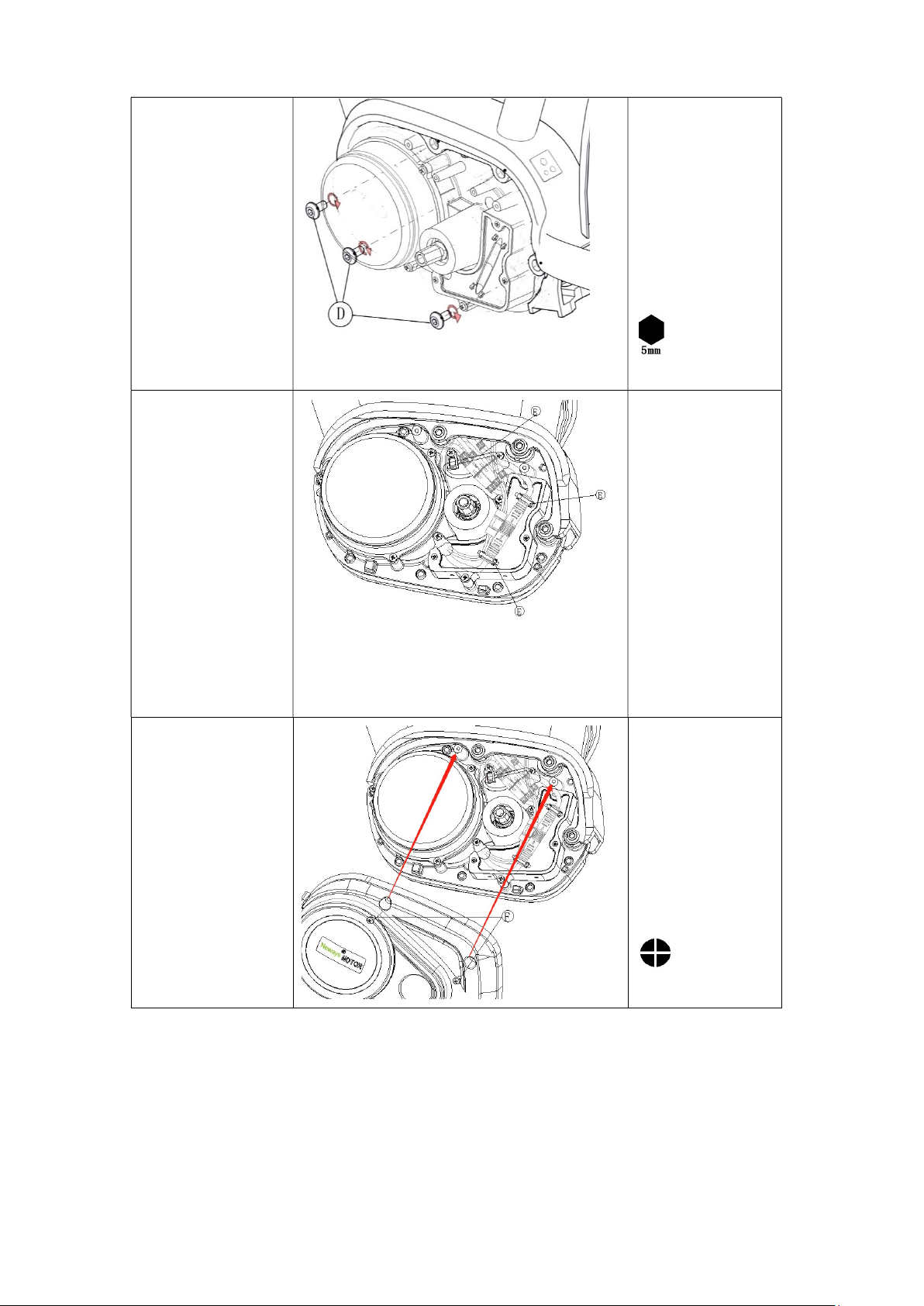
Install the housing of
the drive assembly to
the drive unit.
Locking force
1.5Nm
F. M4*8Screw
tool

Use screws to
lock the bottom
of the housing
and the bottom
of the drive unit
body, as shown
in the figure.
If you consider
arrange the brake
cable or shift cable
at the bottom of the
unit body, lock
the C pressure line
plate together.
Locking force1.5Nm
System wiring
power cable
Connect the positive and
negative connectors of the
power cord to the positive and
negative connectors of the
power supply on the
controller end of the drive unit
(2Core)
Speed sensor line
13
A.Motor housing
screw hole
B.Screw hole for
motor right cover
C.Crimping board
D.M4*8Screw
tool
Connect the positive and
negative connectors of the
power cord to the positive and
negative connectors of the
power supply on the
controller end of the drive unit
a.
Power cord positive and
negative
terminals
Connector
A.Driver unit power cord
female end connector
A.Motor housing
screw hole
B.Screw hole for
motor right cover
C.Crimping board
D.M4*8Screw
Power cord positive and
terminals
A.Driver unit power cord
female end connector

Connect the connector of the
speed sensor unit to the
controller speed sensor
connector of the drive unit
(3Core)
Assembly line
Connect the assembly line
connector to the connector at
the end of the drive unit
(10Core)
Front light wire
Connect
the connector of the
front light wire to the front
light wire connector (2Core)
Rear light wire
Connect the connector of the
rear light cord to the rear light
cord connector of the
drive
unit (2Core)
Variable speed sensor line
Connect the connector of the
variable speed sensor to the
connector of the variable
speed sensor port of the drive
unit (3core)
14
Connect the connector of the
speed sensor unit to the
controller speed sensor
connector of the drive unit
b.
Drive unit speed sensor
male connector
B.Speed
sensor female
connector
Connect the assembly line
connector to the connector at
the end of the drive unit
c
.Drive component end
assembly line female end
connector
C.Assembly line male end
connector
the connector of the
front light wire to the front
d.Drive unit female
connector
D.Headlight cable male end
connector
Connect the connector of the
rear light cord to the rear light
drive
e.Drive unit male connector
E
.Rear light wire female end
connector
Connect the connector of the
variable speed sensor to the
connector of the variable
speed sensor port of the drive
f.Drive
unit female connector
F.Variable speed sensor male
connector
Drive unit speed sensor
male connector
sensor female
.Drive component end
assembly line female end
C.Assembly line male end
d.Drive unit female
D.Headlight cable male end
e.Drive unit male connector
.Rear light wire female end
unit female connector
F.Variable speed sensor male

15
Install the front chain ring
Insert the front gear piece into
the spline shaft in the drive
assembly along the spline
direction, and use a tool
(bicycle bottom shaft spline
sleeve) to lock the locking bolt
counterclockwise.
Locking force
30—35N.m
A. Front sprocket
B. Locking bolt (M24*1)
Install the full-inclusive chain guard
This kind of full-wrapped
chain cover needs to be
used with the chain
cover pressure plate and
screws as shown in the
figure to be fixed with
the drive assembly.

16
Open this kind of
all-inclusive chain
cover according to the
product manual and
adjust it to the proper
position so that the
inner side of the chain
cover is close to the
convex surface of the
outer side of the drive
unit. Then use screws
to press the pressure
plate against the inner
wall of the chain cover
and lock the screws.
Locking force:2N.m
A.Full chain
cover
B.Full-inclu
sive chain
cover
tablet
C.M4Phillip
s screw
tool
Install the sprocket
according to the
installation method of
the sprocket.
After installing the gears,
follow the chain cover
product instructions to
assemble the chain
cover completely.

Install half-
wrapped chain guard
Adjust the attachment angle
of the half-
pack chain cover,
and lock the half-
pack chain
cover removal and
attachment with the locking
part of the drive unit with
screws.
Locking force:2N.m
Install the sprocket in
place
according to the installation
method of the sprocket.
Fasten the half-
pack chain
cover with the half-
pack chain
cover bracket with screws.
Locking force 2 N.m
17
wrapped chain guard
Adjust the attachment angle
pack chain cover,
pack chain
cover removal and
attachment with the locking
part of the drive unit with
place
according to the installation
pack chain
pack chain
A. Half-wrappe
d chain cover
mounting
bracket
B. M4Phillips
screw
tool
D.M4Phillips
screw
E.Half-wrapped
chain cover
tool

Install the crank
Mount
the right crank on
the right bottom bracket,
And use one M8 hexagon
socket screws to lock, install
the left crank in the same
way.
Locking force 35-40N.m
Change gear oil operation
Drain oil
Place the right side of
the drive unit up and
horizontally, and
open the oil filling
hole bolt and the oil
drain hole bolt
respectively.
18
the right crank on
the right bottom bracket,
And use one M8 hexagon
socket screws to lock, install
the left crank in the same
Change gear oil operation
A.Right crank
B.Crank
mounting
screwM8
tool
A. Filling hole
B. Oil drain hole
C. Grease hole
bolt
D. Oil drain bolt
tool
Table of contents
Popular Engine manuals by other brands


Parker
Parker ETH Series Mounting instructions

MTU
MTU 12V2000M84 operating instructions

Nice
Nice Era Star P Series Instructions and warnings for installation and use

MTU
MTU 20 V 4000 M93 operating instructions

King gates
King gates Modus Installation and use instructions and warnings

Siemens
Siemens M20 Terminal Technical description