6
4. ASSEMBLY
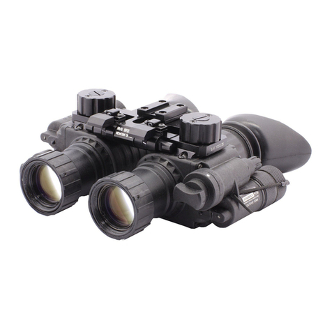
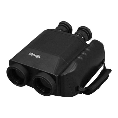
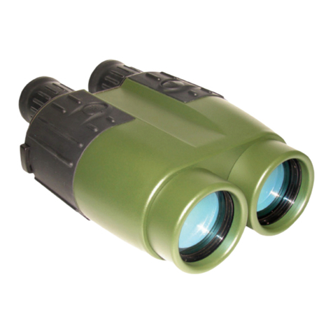
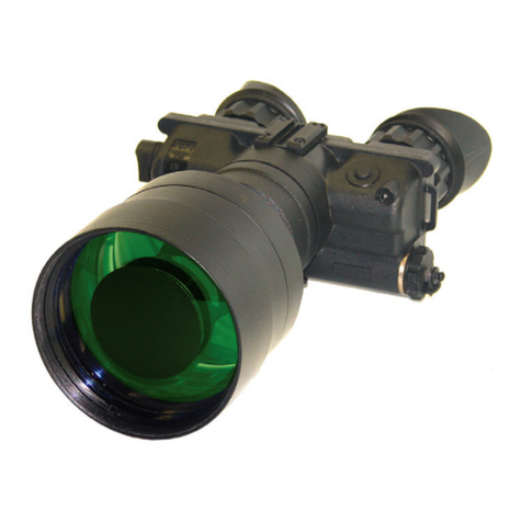
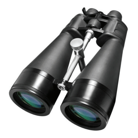
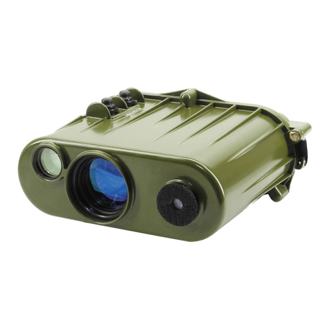
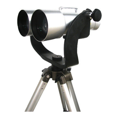
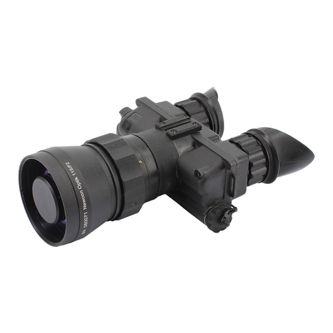
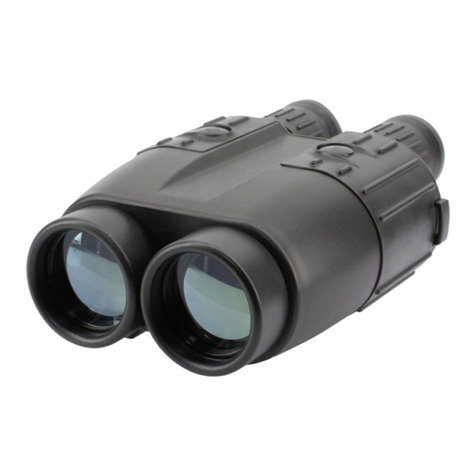
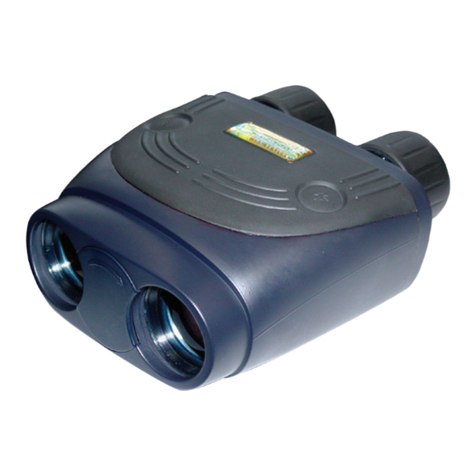
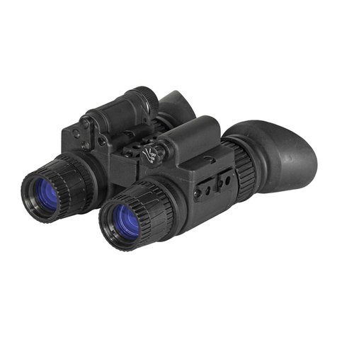
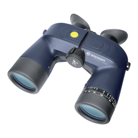
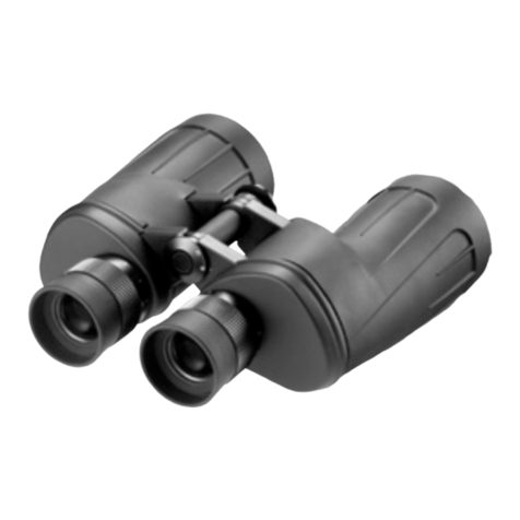
The binoculars appearance is shown on the Figure 1. It consists of the binocular itself,
U-mount and tripod.
4.1 Basic Optical Train
The optical train of the device is a telescopic system which consists of two branches.
Each branch has an objective composed of lenses I, 2 (Fig. 1) and prism 3, 4, 14, an
eyepiece composed of lenses 5, 6 and cemented lenses 7, 8, 9, changeable light filters
10, 11.
The light beams which come from the object to be viewed pass through the objective,
and after collecting in its focal plane from an inverted image of the object.
There is a prismatic inversion system composed of prisms 3, 4, 14 in the focal plane
of the eyepiece for obtaining an erect image. The prisms serve also for deviation of the
sighting line by 30 upwards and for changing the distance between the exit pupils and
between the entrance pupils.
Reticle 13 which is a plane - parallel plate is positioned in the focal plane of the right
objective. The plate is engraved with three scales: vertical, horizontal and angle -
measuring once. The field of view is shown in Fig. 7.
The vertical and horizontal scales are intended for measuring the angular dimensions of
the objects. The division value is 0-05. The total range of the vertical scale is 0-30 and
horizontal one is ± 0-30. The central sign (cross-hairs) indicates a centre of the field of
view. Light filters 9, 10 (Fig.8) facilitate the condition observation.
4.2 Design of the device
The device consists of two telescopes, casings 2 and 4 (fig. 2) which are connected
below by means of a mechanism of the eye distance with handwheel 5 (Fig.5).
Each telescope consists of a casing, objective 3 (Fig. 4), block of prisms 9, eyepiece,
desiccator 10,valve 12 and blind.
The eyepieces are set for the image sharpness of the target by an observer’s eye by
rotation of scales 1 (Fig.3). The value of the diopter setting of the eyepieces (in the
range from minus 3 to 5 diopters) is determined by scale 1 (Fig. 3) and indices on
casings 2 and 6. In operation with the device, if it is necessary, changeable light filters
9, 10 (Fig. 8) of a required colour from the single STA kit are put on.
Headrest 8 (Fig. 4) is inserted in bracket 6 fastened on casing 2 (Fig. 2). The headrest
serves as a support for the head and ensures a convenient operation. It can be moved
and to be fixed with the use of handle 7 (Fig.4).
Desiccators 10 (Fig.4) to be filled with silica gel are fastened on casings 2 and 4 (Fig.
2) and serve for constant desiccation of the device inner cavity.
Blinds 3 and 5 (Fig. 2) are put on casings 2 and 4 on the side of the objectives, protect
