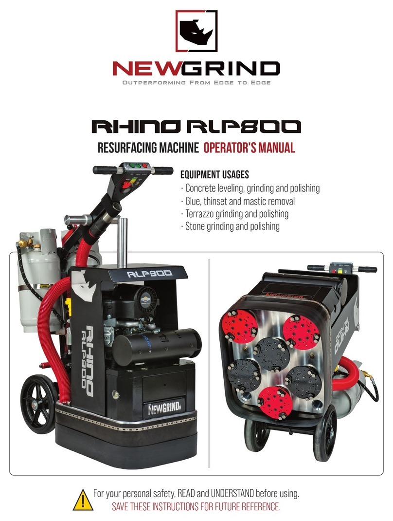
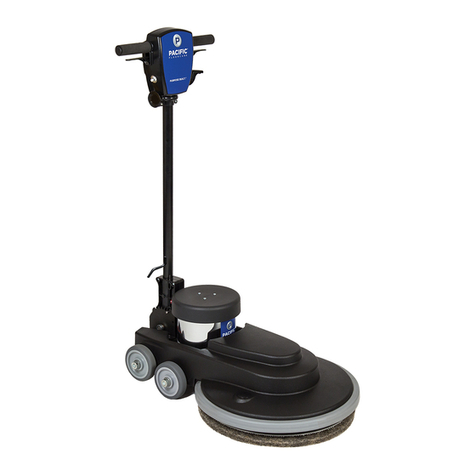
Newgrind Rhino RS150 User manual

Rhino Resurfacing Machine
Operator’s Manual
RS150 1.5HP
RM250 3HP

For your personal safety, READ and UNDERSTAND before using.
SAVE THESE INSTRUCTIONS FOR FUTURE REFERENCE.

GENERAL SAFETY RULES
WARNING! Read and understand all
instructions. Failure to follow all instruc-
tions listed below, may result in electric
shock, re and/or serious personal injury.
SAVE THESE INSTRUCTIONS.
Work Area
1. Keep your work area clean and well lit.
Cluttered oors and dark areas invite
accidents.
2. Do not operate equipment in
explosive atmospheres, such as in the
presence of ammable liquids, gases or
dust. Grinding can create sparks which
may ignite the dust or fumes.
3. Keep bystanders, children, and
visitors away while operating equip-
ment. Distractions can cause you to lose
control.
Electrical Safety
4. Do not abuse the cord. Never use the
cord to pull the equipment or pull the
plug from an outlet. Keep cord away
from heat, oil, sharp edges or moving
parts. Replace damaged cords immedi-
ately. Damaged cords increase the risk
of electric shock.
5. When operating equipment outside,
use an outdoor extension cord marked
"W-A" or "W". These cords are rated for
outdoor use and reduce the risk of
electric shock.
6. Avoid accidental starting. Be sure stop
button is depressed before plugging in.
Starting equipment with your nger on
the start buttons or plugging in equip-
ment that have the buttons depressed
invites accidents.
Personal Safety
7. Stay alert, watch what you are doing
and use common sense when operating
equipment. Do not use equipment while
tired or under the inuence of drugs,
alcohol, or medication. A moment of
inattention while operating equipment
may result in serious personal injury.
8. Do not overreach. Keep proper
footing and balance at all times. Proper
footing and balance enables better
control of the equipment in unexpected
situations.
9. Use safety equipment. Always wear
eye protection. Dust mask, non-skid
safety shoes, hard hat, or hearing
protection must be used for appropriate
conditions. Ordinary eye or sunglasses
are NOT eye protection.
10. DO NOT Turn on equipment while
the machine is tilted back. Any tooling
fastened to the machine can eject and
become a lethal projectile.
Equipment Use and Care
11. The equipment is designed to
remove excess surface material. To
prevent damage to the equipment
and/or serious personal injury, beware
of protruding objects or other debris on
or embedded in the surface being
nished.
12. Disconnect the plug from the power
source before making any adjustments,
changing accessories, or storing equip-
SPECIFICATIONS
Model RM150 1.5HP RM150 3HP
Input Power
120V 50/60Hz
380
-
460V
+/
-
15%50/60Hz
Amps
12A
14
-
16A
Plug Type
15A 125V
3P4W 30A 480V 3~
(NEMA L16-30P)
Disc Diameter
5" / 127mm
Disc Speed (RPM)
133-665 200-900
Machine Width
14" / 355mm
Weight
150lbs / 69kg 150lbs / 69kg

ment. Such preventive safety measures
reduce the risk of starting the equip-
ment accidentally.
13. Maintain equipment with care. Keep
tools and accessories in good condition.
Properly maintained tools with sharp
cutting edges are less likely to fail and
are easier to control.
14. Check for binding of moving parts,
breakage of parts, and any other condi-
tion that may aect the equipment's
operation. If damaged, have equipment
serviced before using. Many accidents
are caused by poorly maintained equip-
ment.
15. Use only tools and accessories that
are recommended by the manufacturer
for your equipment. Tools and accesso-
ries that may be suitable for style of
equipment, may become hazardous
when used on another style of equip-
ment.
SERVICE
16. DO NOT modify the machine. Modi-
cations will void warranty and could
result in unsafe operation of equipment.
17. Equipment service should be
performed only by qualied repair
personnel. Service or maintenance
performed by unqualied personnel
could result in a risk of injury.
18. When servicing equipment, use only
identical replacement parts. Use of
unauthorized parts may create a risk of
electric shock or injury.
USE PROPER EXTENSION CORD. Make
sure your extension cord is in good
condition. When using an extension cord,
be sure to use one heavy enough to carry
the current your product will draw. An
undersized cord will cause a drop in line
voltage resulting in loss of power and
overheating. For model HDX465 use
10gauge cord or larger. For model
HDX465HV use 12 gauge cord or larger. If
in doubt, use the next heavier gauge. The
smaller the gauge number, the heavier
the cord.
SPECIFIC SAFETY RULES
DO NOT let comfort or familiarity with
product (gained from repeated use)
replace strict adherence to equipment
safety rules. If you use this equipment
unsafely or incorrectly, you can suer
serious personal injury.
1. Tools and accessories must be rated
for at least the speed stated on the
equipment serial plate. Tools and other
accessories running over rated speed
can y apart and cause injury.
2. Always use safety glasses or goggles.
Ordinary eye or sun glasses are NOT
safety glasses.
3. Make sure cord is clear of wheels and
cutting discs. Do not wrap cord around
your arm or wrist. If control of equip-
ment is lost, cord may become wrapped
around you and cause personal injury.
4. Adequate ventilation of your work
area is very important when using
equipment. Use a dust mask or appro-
priate respirator.
5. Due to the dusty nature during use of
this equipment, be sure to clean equip-
ment often to remove dust accumula-
tions. Carefully blow the dust out of the
motor, VFD and dust covered areas
frequently.
6. Always install the dust skirt before
operation.
7. Check the tools and accessories
carefully for cracks or damage before
operation. Replace cracked or damaged
tools or and accessories immediately.
8. Hold the equipment rmly with both
hands during operation.
9. Do not leave the equipment running
unattended.
10. Do not touch the tools immediately
after operation; they may be extremely
hot and could burn your skin.
WARNING: Misuse or failure to follow
the safety rules stated in this instruction
manual may cause serious personal
injury. SAVE THESE INSTRUCTIONS.

Machine Operation:
The Variable Frequency Drive (VFD) is
designed to allow the user to operate the
equipment on either single phase or
three phase power for the 3HP model.
The equipment is able to operate on
either 50 Hz or 60 Hz frequencies. The
VFD will automatically adjust for phase
or frequency input which will raise or
lower head speed on the machine.
LED DISPLAY – Shows PAD speed when
machine is running and says stop when
plugged in but not running.
Starting the equipment:
Apply downward pressure on the handle
to alleviate some pressure o of the tools
and press the green or blue start button.
Once the equipment gets started, gently
release the downward pressure and start
grinding.
The equipment is designed to rotate the
tooling in either the forward direction
(green button) or reverse direction (blue
button) depending on operating needs.
Use the equipment in the forward rotation
mode (green button) unless reverse
rotation is needed. This will ensure consis-
tent tool wear and tool prole. The use of
the equipment in the reverse rotation is
only needed when surface being nished
is uneven and causes the equipment to
pull in an undesired direction or when the
tooling is glazed and needs to be
re-dressed.
Use the knob, located on the right side of
the handle control box, to adjust speed of
equipment.Before starting the equipment,
ensure that the speed is set to the
lowest speed available as displayed on
the VFD screen. Doing so will prevent
unexpected high speed start up which
could cause some tools to eject or
cause undesirable marks to the surface
being finished.
DO NOT LIFT THE EQUIPMENT OFF THE
GROUND WHILE STARTING! Doing so can
cause the tools to release from the equip-
ment and cause damage to the surface
being nished and harm to the user!
Stopping the equipment:
To stop the equipment, turn speed control
knob to the slowest setting and push the
red stop button on the face of the handle
Changing tools and accessories:
Always turn o and disconnect power
from the machine when performing any
operations to the bottom of the machine!
When removing and inserting tool
plates or adapter plates, be sure to
inspect rubber grommets for signs for
wear and replace any damaged
grommets.
Using grommets that are damaged
or missing can cause unexpected
equipment operation and increase the
chance of tool plate / adapter plate
ejection or violent vibration leading to
loss of control of equipment!
Handle adjustment:
To adjust the handle, pull the hand
latch or step on foot latch on the
handle and move handle up or down
to the desired position. Avoid
stepping on or tangling handle
control cable when adjusting the handle
position. Make sure that the latch clicks
in place

when the desired position is achieved.
Failure to check for positive engagement
could result in damage to the equipment
or injury to the user as the handle could
release unexpectedly when the machine
is being operated or tilted back!
VFD features:
The machine is outtted with a VFD
(Variable Frequency Drive) enabling the
user to select the desired operating speed.
The VFD also possesses many features
such as:
- Under voltage protection - Over current
protection
- 60Hz and 50Hz capability (international)
- Wide voltage range
(200-230V +/- 15% for 230V model)
(380-460V +/- 15% for 460V model)
- Soft start
- Speed display - Load display
- Current limiting
Maintenance:
General:
- Disconnect power before performing
any maintenance, cleaning, or repair to
your equipment!
- When the equipment is not in use,
make sure that the adapter plate assem-
blies have something attached to them
to protect the Velcro. Resting the
machine directly on unprotected Velcro
will crush the fastening material causing
the Velcro to become unusable.
Daily:
- Wipe down the equipment after every
job.
- Gently remove dirt and debris from the
Velcro hook material using a wire brush.
This will ensure maximum adhesion.
- Check that the handle bolts are tight.
- Vacuum or wipe underside of machine.
- Inspect plug ends for signs of carbon
deposits or arcing.
- Check all fasteners and tighten if
necessary.
Weekly:
- Inspect handle wires for damage.
- Blow o VFD heat sink with
compressed air. - Blow out VFD cooling
n fan(s) with low
pressure compressed air (30psi or less).
- Cleaning the fan(s) prevents fan failure
and
potential VFD overheating. Do not
over-speed
the fan(s) with compressed air!
- Blow o motor fan with compressed
air.
- Remove tool plate holders and wipe
down
bearing shields with a damp cloth. Do
not use any sharp object or abrasive pad
to clean the bearing shields. This can
compromise the bearing seal! Re-install
tool plate drivers using blue medium
strength thread locking compound.
- Using a soft scrub pad, remove any
excess dirt build up from the bottom
plate and back side of pad drivers.
- Inspect tool plate driver grommets for
signs of wear. Replace grommets that
show signs of extensive wear.
Monthly:
- Check all strain reliefs and make sure
they are tight so as to avoid cords being
pulled out of the VFD or handle.
- Remove tool plate drivers and inspect
threads to make sure that there are no
signs of cross threading or stripping.
- Clean and lubricate wheels.
- Clean and lubricate latch mecha-
nisms.

The VFD is protected from voltage
fluctua-tions within the specified
voltage range. Check voltage before
plugging in equip-ment to insure safe
operation.
If a machine is plugged into a power
source that is above the machine’s
maximum voltage capability (ex. 230V
model plugged into a 460V power
source) this will damage and/or destroy
the internals of the VFD and void
warranty!
LIMITED EQUIPMENT WARRANTY OF SALE
New Grind Inc. warrants that each
new unit manufactured for New Grind Inc.
to be free from defects in material
and workmanship in normal use and
service for a period of (2) one year from
date of shipment to the original retail
or equip-ment rental center owner.
Accessories or equipment furnished and
installed on the product by New Grind
Inc. but manufac-tured by others,
including, but not limited to engines,
motors, electrical components,
transmissions etc., shall carry the
accesso-ry manufacturers own
warranty. New Grind Inc. will, at its
option, repair or replace, at the New
Grind Inc. factory or at a point designated
by New Grind Inc. any part which shall
appear to the satisfaction of New Grind
Inc. inspection to have been defective in
material or workmanship. New Grind Inc.
reserves the right to modify, alter and
improve any part or parts without
incurring any obligation to replace
any part or parts previously sold
without such modified, altered
or improved part or parts. This
warranty is in lieu of and excludes all
other warranties, expressed, implied,
statutory, or otherwise created under
applicable law including, but not
limited to the warranty of
merchantability and the warranty
of fitness for a particular purpose in no
event shall seller or the manufacturer
of the product be liable for special,
incidental, or
For VFD error codes please see attached document

consequential damages, including loss of
prots, whether or not caused by or result-
ing from the negligence of seller and/or
the manufacturer of the product unless
specically provided herein. In addition,
this warranty shall not apply to any
products or portions there of which have
been subjected to abuse, misuse, improp-
er installation, maintenance, or operation,
electrical failure or abnormal conditions
and to products which have been
tampered with, altered, modied,
repaired, reworked by anyone not
approved by seller or used in any manner
inconsistent with the provisions of the
above or any instructions or specications
provided with or for the product
FORCE MAJEURE
Seller’s obligation hereunder are subject
to, and Seller shall not be held responsible
for, any delay or failure to make delivery of
all or any part of the product due to labor
diculties, res, casualties, accidents, acts
of the elements, acts of God, transporta-
tion diculties, delays by a common
carrier, inability to obtain product, materi-
als or components or qualied labor
sucient to timely perform part of or all of
the obligations contained in these terms
and conditions, governmental regulations
or actions, strikes, damage to or destruc-
tion in whole or part of manufacturing
plant, riots, terrorist attacks or incidents,
civil commotions, warlike conditions,
ood , tidal waves, typhoon, hurricane,
earthquake, lightning, explosion or any
other causes, contingencies or circum-
stances within CANADA not subject to the
Seller’s control which prevent or hinder
the manufacture or delivery of the
products or make the fulllment of these
terms and conditions impracticable. In the
event of the occurrence of any of the
foregoing, at the option of Seller, Seller
shall be excused from the performance
under these Terms and Conditions, or the
performance of the Seller shall be
correspondingly extended. This document
sets forth the terms and conditions pursu-
ant to which the purchaser (“Purchaser”)
will purchase and New Grind Inc. (“Seller”)
will sell the products, accessories, attach-
ments (collectively the products “) ordered
by the Purchaser. These terms and condi-
tions shall govern and apply to the sale of
Seller’s products to Purchaser, regardless
of any terms and conditions appearing on
any purchase order or other forms submit-
ted by Purchaser to Seller, or the inconsis-
tency of any terms therein and herein.
LIABILITY LIMITATIONS
The remedies of the user set forth under
provisions of warranty outlined above are
the exclusive and total liability of New
Grind Inc. with the respect to their sale or
the equipment and service furnished
hereunder, in connection with the perfor-
mance or
breach thereof, or from the sale, delivery,
installation, repair or technical direction
covered by or furnished under the sale,
whether based on contract, warranty,
negligence, indemnity, strict liability, or
otherwise shall not exceed the purchase
price of the unit of equipment upon which
such liability is based.
New Grind Inc. will not in any event be
liable to the user, any successors in
interest or any beneciary or assignee
relating to this sale for any consequential,
incidental, indirect, special or punitive
damages arising out of this sale or any
breach thereof, or any defects on, or
failure of, or malfunction of the equipment
under this sale based upon loss of use, lost
prots or revenue, interest, lost goodwill,
work stoppage, impairment of other
goods, loss by reason of shutdown or non-
operation, increased expenses of opera-
tion of the equipment, cost of purchase or
replacement power of claims of users or
customers of the user for service interrup-
tion whether or not such loss or damage is
based on contract, warranty, negligence,
indemnity, strict liability, or otherwise.
New Grind Inc. reserves the right to
modify, alter and improve any part or parts
without incurring any obligation to
replace any part or parts previously sold
without such modied, altered or
improved part or parts.
No person is authorized to give any other
warranty or to assume any additional

obligation on New Grind Inc.'s behalf
unless made in writing and signed by an
ocer of New Grind Inc.
TERMS & CONDITIONS
1. PRICE
All prices set forth on any purchase
order or other document are F.O.B.
Sellers facility or distribution point, as
may be determined by Seller
(F.O.B.Point). All prices are exclusive of
any and all taxes, including, but not
limited to, excise, sales, use, property or
transportation taxes related to the sale
or use of the products, now or hereafter
imposed, together with all penalties and
expenses.
Purchaser shall be responsible for
collecting and/or paying any and all
such taxes, whether or not they are
stated in any invoice for the Products.
Unless otherwise specied herein, all
prices are exclusive of inland transporta-
tion, freight, insurance and other costs
and expenses relating to the shipment
of the Products from the F.O.B. point to
Purchaser’s facility. Any prepayment by
Seller of freight insurance and other
costs shall be for the account of
Purchaser and shall be repaid to Seller.
2. PAYMENT TERMS
Payment terms are as follows:
New Grind Inc. Machines - Payment prior
to delivery.
*All past due accounts are subject to a
late payment fee of 1.5% per month or a
maximum allowed by law if dierent,
along with the expenses incidental to
collection including reasonable
attorney’s fees and costs.
*Seller reserves the right to hold
shipments against past due accounts.
*Seller reserves the right to alter
payment terms.
3. FREIGHT TERMS
All shipments will be made F.O.B.
shipping point as designated in these
Terms and Conditions, and title shall
pass at the F.O.B. point. Delivery to the
initial common carrier shall constitute
delivery to the Purchaser. Any claims for
loss or damage during shipment are to
be led with carrier by the Purchaser.
Seller will not assume responsibility for
the performance of the carrier.
Backorders will be shipped in the most
practical fashion with charges consis-
tent with our freight policy established
with the original order. UPS, FED EX,
MAIL or shipments by other couriers are
subject to the same terms and condi-
tions as outlined in paragraph #3
”Freight Terms”.
4. DELIVERY, DAMAGES, SHORTAGES
Seller shall use reasonable eorts to
attempt to cause the Products to be
delivered as provided for in these Terms
& Conditions. Delivery to the initial
common carrier shall constitute the
delivery to the Purchaser. Sellers
responsibility, in so far as transportation
risks are concerned ceases upon the
delivery of the Products in good condi-
tion to such carrier at the F.O.B. point
and all the Products shall be shipped at
the Purchaser’s risk. Seller shall not be
responsible or liable for any loss of
income and/or prots, or incidental,
special, consequential damages result-
ing from Seller’s delayed performance in
shipment and delivery.
5. RETURN OF DEFECTIVE PRODUCTS
Defective or failed material shall be held
at the Purchaser’s premises until autho-
rization has been granted by Seller to
return or dispose of Products. Products
that are to be returned for nal inspec-
tion must be returned Freight Prepaid in
the most economical way. Credit will be
issued for material found to be defective
upon Seller’s inspection based on prices
at time of purchase.
6. PRODUCTS ORDERED IN ERROR
Products may be returned, provided
that claim is made and Seller is notied
within 7 days of receipt of Products, and
the Products are in original buyer’s
possession not more than 30 days prior
to return, subject to Seller’s approval. If
Products are accepted for return, they
must be Freight Prepaid and buyer will
be charged a minimum of 15% restock-

ing charge, plus a charge back for
outbound freight charges if the original
order was shipped prepaid. Returns are
not accepted for any Products that are
specically manufactured to meet the
buyer’s requirement of either specica-
tions or quantity.
AGREEMENTS
These Terms and Conditions constitute the
entire agreement between Seller and
Purchaser as it relates to terms and condi-
tions of sale, and supersedes any and all
prior oral or written agreements,
correspondence, quotations or under-
standings heretofore in force between the
parties relating to the subject matter
hereof. There are no agreements between
Seller and Purchaser with respect to the
Product herein except those specically
set forth in and made part of these terms
and conditions. Any additional terms,
conditions and/or prices are rejected by
Seller. These terms and conditions may be
modied, cancelled or rescinded only by a
written agreement of both parties execut-
ed by their duly authorized agents.
New Grind Inc.
103B- 81 Golden Dr
Coquitlam BC
V3K 6R2
Telephone:
1-888-467-0242
carissa@newgrind.com
www.newgrind.com

www.newgrind.com

SV01C
Operating Instructions
SMVector - Frequency Inverter

37
SV01C
Troubleshooting and Diagnostics
5.3 Fault Messages
The messages below show how they will appear on the display when the drive trips. When looking at the Fault History (P500), the
.will not appear in the fault message.
Fault Cause Remedy (1)
High Temperature fault Drive is too hot inside • Reduce drive load
• Improve cooling
LAssertion Level fault • Assertion Level switch is changed
during operation
• P120 is changed during operation
• P100 or P121...P123 are set to a
value other than 0 and P120 does
not match the Assertion Level
Switch.
• Make sure the Assertion Level switch
and P120 are both set for the type
of input devices being used, prior to
setting P100 or P121...P123.
See 3.2.3 and P120.
Personality fault Drive Hardware • Cycle Power
• Power down and install EPM with valid
data
• Reset the drive back to defaults (P199
= 3, 4) and then re-program
• If problem persists, contact factory
technical support
Control fault An EPM has been installed that is either
blank or corrupted
f F Incompatible EPM fault An EPM has been installed that contains
data from an incompatible parameter
version
.d Dynamic Braking fault Dynamic braking resistors are overheating • Increase active decel time
(P105, P126, P127).
• Check mains voltage and P107
External fault • P121…P123 = 21 and that digital input
has been opened.
• P121…P123 = 22 and that digital input
has been closed.
• Correct the external fault condition
• Make sure digital input is set properly
for NC or NO circuit
EPM fault EPM missing or defective Power down and replace EPM
Internal faults Contact factory technical support
.Invalid message received • A network message was received while
in Remote Keypad mode
• A remote keypad message was
received while in Network mode
Only the remote keypad or the network
can be connected at one time; see P100
LLoss of 4-20 mA signal fault 4-20 mA signal (at TB-25) is below 2 mA
(P163 = 1)
Check signal/signal wire
OEM Defaults data fault Drive is powered up with
P199 =1 and OEM settings in the EPM are
not valid.
Install an EPM containing valid OEM
Defaults data or change P199 to 0.
High DC Bus Voltage fault Mains voltage is too high Check mains voltage and P107
Decel time is too short, or too much regen
from motor
Increase active decel time
(P105, P126, P127) or install Dynamic
Braking option
(1) The drive can only be restarted if the error message has been reset

38 SV01C
Troubleshooting and Diagnostics
Fault Cause Remedy (1)
Digital Input
Configuration fault (P121...
P123)
More than one digital input set for the
same function
Each setting can only be used once (except
settings 0 and 3)
Only one digital input configured for MOP
function (Up, Down)
One input must be set to MOP Up, another
must be set to MOP Down
PID mode is entered with setpoint
reference and feedback source set to the
same analog signal
Change PID setpoint reference (P121…
P123) or feedback source (P201).
One of the digital inputs (P121…P123) is
set to 10 and another is set to 11…14.
Reconfigure digital inputs
One of the digital inputs (P121…P123)
is set to 11 or 12 and another is set to
13 or 14.
PID enabled in Vector Torque mode (P200
= 1 or 2 and P300 = 5) PID cannot be used in Vector Torque mode
Remote keypad fault Remote keypad disconnected Check remote keypad connections
LLow DC Bus Voltage fault Mains voltage too low Check mains voltage
1No Motor ID fault An attempt was made to start the drive
in Vector or Enhanced V/Hz mode prior to
performing the Motor Auto-calibration
See P300…P399 for Drive Mode setup
and calibration.
Module communication fault Communication failure between drive and
Network Module.
Check module connections
Network Faults Refer to the module documentation. for
Causes and Remedies.
Output fault:
Transistor fault
Output short circuit Check motor/motor cable
Acceleration time too short Increase P104, P125
Severe motor overload, due to:
• Mechanical problem
•Drive/motor too small for application
• Check machine / system
• Verify drive/motor are proper size for
application
Boost values too high Decrease P168, P169
Excessive capacitive charging current of
the motor cable
• Use shorter motor cables with lower
charging current
• Use low capacitance motor cables
• Install reactor between motor and drive.
Failed output transistor Contact factory technical support
Output fault: Ground fault Grounded motor phase Check motor and motor cable
Excessive capacitive charging current of
the motor cable
Use shorter motor cables with lower
charging current
Motor Overload fault Excessive motor load for too long • Verify proper setting of P108
• Verify drive and motor are proper size
for application
(1) The drive can only be restarted if the error message has been reset

39
SV01C
Troubleshooting and Diagnostics
Fault Cause Remedy (1)
Flying Restart fault Controller was unable to synchronize with
the motor during restart attempt; (P110
= 5 or 6)
Check motor / load
Single-Phase fault A mains phase has been lost Check mains voltage
Start fault Start command was present when power
was applied (P110 = 0 or 2).
• Must wait at least 2 seconds after
power-up to apply Start command
• Consider alternate starting method (see
P110).
(1) The drive can only be restarted if the error message has been reset

AC Technology Corporation • 630 Douglas Street • Uxbridge, MA 01569 • USA
+1 (508) 278-9100
SV01C
This manual suits for next models
1
Table of contents
Other Newgrind Floor Machine manuals
