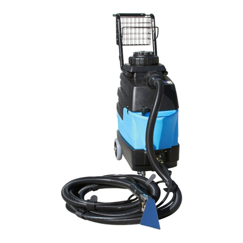
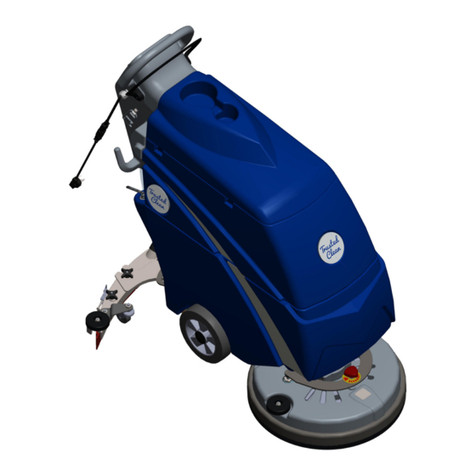
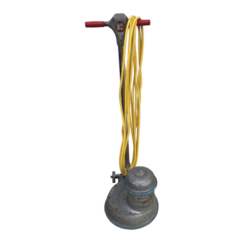
KENT C-4 User manual

TABLE OF CONTENTS
Contact Information:

INTRODUCTION
BEFORE YOU USE YOUR OWNER’S MANUAL, PLEASE READ
THIS INTRODUCTION ALL THE WAY THROUGH.
WHEN THE MACHINE IS DELIVERED:
BEFORE OPERATING THE MACHINE:
WARRANTY:
THIS MACHINE IS FOR COMMERCIAL USE.
IMPORTANT SAFETY INSTRUCTIONS
When using an electrical appliance, basic precautions should always be
followed, including the following:
READ ALL INSTRUCTIONS BEFORE USING MODEL C-4.
GENERAL INSTRUCTIONS
1

WARNING – TO REDUCE THE RISK OF FIRE, ELECTRICAL SHOCK, PERSONAL INJURY OR
DAMAGE TO MODEL C-4:
GROUNDING INSTRUCTIONS
FOR CUSTOMERS IN CANADA:
CAUTION!
2

CARPET CLEANING INSTRUCTIONS
SECTION A: PREPARING CARPET
1. Vacuum carpet with your vacuum cleaner, NOT the C-4 extractor. 2. Pre-treat spotted and heavily soiled areas of carpet.
SECTION B: PREPARING THE MACHINE
1. Pull Bucket Handle outward, lift the Lid and remove Bucket. 2. Fill Bucket with hot tap water to the 2.5 or 3.5 gallon fill line. Add 2
oz. (60 mL) of cleaner per gallon of water. 3. IMPORTANT: Pour Bucket contents into the Solution Tank.4. Return Bucket, Lid and
Handle.
B1 B2 B3 B4
WARNING!: Do not use bleach or dye in this machine. User will be liable for all damage done to machine, carpets and upholstery.
SECTION C: CLEANING CARPET
1. Adjust Handle to desired height using Black “T” Handle. 2. Make sure all Switches are off. Plug machine in. 3. Tilt the machine
back and move to start position. 4. Turn ON the Suction Switch. IMPORTANT: Hand Tool Switch must be OFF during carpet
cleaning! 5. Squeeze Spray/Brush Trigger as you pull the machine backwards.
C1 C2 C3 C4
TIP: Strokes should be at a slow, steady pace, five feet long with a two-inch overlap. Release Spray/Brush Trigger four inches before
end of stroke. Heavily soiled areas may require a second cleaning at a right angle to the first cleaning.
IMPORTANT: After moving furniture on damp carpet, place foil under the legs IMMEDIATELY to avoid carpet staining.
C6 C7
IMPORTANT: If foam is in the
left Lid Tube, add 2 ounces (60
mL) of Anti-Foam to the
Bucket. Or, empty Bucket
contents and replace without
refilling the machine.
6. As you clean, dirty solution
passes through the right Lid
Tube. When extraction
ceases, machine is empty. 7.
Turn OFF Switches. Discard
dirty water. Rinse Bucket.
Refill according to instructions.
3

SECTION D: CLEANING STAIRS
Hand Tool HAND TOOL HOOK UP
IMPORTANT:
Make sure it is empty of all solution! EMPTYING UNUSED
SOLUTION
Suction Hand Tool Switches Hand Tool Trigger
UPHOLSTERY CLEANING
SECTION E: TESTING COLOR FASTNESS & FILLING THE MACHINE
your vacuum, NOT the C-4 extractor
IMPORTANT: Bucket Solution Tank
SECTION F: HAND TOOL HOOK UP
Switches Gray
Black Cuffs Gray
Hand Tool Cuff Gray Machine Cuff
Solution Hose
Coupler brass fixture
Solution Hose Coupler
Coupler Sleeve
Coupler Hose
Solution Hose
SECTION G: CLEANING UPHOLSTERY
Suction Hand Tool Switches
Trigger
TIP:
EMPTYING UNUSED SOLUTION
Drain WARNING: DO NOT USE TO CLEAN HAITIAN COTTON!!
AFTER EACH USE
Lid
Solution Tank
Bucket
Vac Nozzle
Brush
Brush Chamber
4

MACHINE OPERATION AND TROUBLESHOOTING
PROBLEM: LOSS OF ELECTRICAL POWER
PROBLEM: LOSS OF VACUUM / LITTLE OR NO SUCTION
PROBLEM: LACK OF WATER PRESSURE
PROBLEM: NO BRUSH MOVEMENT
KENT INVESTMENT CORPORATION LIMITED WARRANTY
EXCEPTION:
5

SYMPTOM POSSIBLE CAUSE SOLUTION
@abaiWdfafZW_SUZ[`W # 4g[^V[`YU[dUg[fTdWS]Wdfd[bbWV # G`b^gYS`kafZWdWcg[b_W`fa`
fZWeS_WU[dUg[f IS[fX[hW_[`gfWe
dWeWfU[dUg[f Note:;XTdWS]Wd
Ua`f[`gWefafd[bfdkagf^Wfea`
S`afZWdU[dUg[f ;X`WiU[dUg[f
Ua`f[`gWefafd[b6A@AFgeWfZW
g`[f 3^^_afadeS`Vi[dWe_gefTW
WjS_[`WVXadVWXWUf
$ 6WXWUf[hWiS^^agf^Wf $ B^gY_SUZ[`W[`faV[XXWdW`fagf^Wf
Also:5ZWU][Xagf^Wf[ei[dWVfaS
^[YZfei[fUZ
% 6WXWUf[hWPlug. % DWb^SUWPlug (10109).
& >aaeWBaiWd5a``WUf[a` & 5ZWU]Wire Nuts (10149) faT^SU]
S`ViZ[fWi[dWe
' 6WXWUf[hW Power Cord. ' DWb^SUW Power Cord (18205).
BaiWd[e[`fWd_[ffW`ffaS^^adea_WaX
fZW_afade
# >aaeWTerminal ad Wire Nut. # DWb^SUW^aaeWTerminals adWire
Nut.
$ 4gd`WVadUaddaVWVTerminals. $ DWb^SUWTerminals.
% 6WXWUf[hWSwitch. % DWb^SUWSwitch (10108/18207).
& 6WXWUf[hWWire adPower Cord. & DWb^SUW Wire adPower Cord
(18205).
7^WUfd[US^EZadf # 6S_SYWVad^aaeWi[dW
Ua``WUf[a`fZSffagUZWeS`k_WfS^
a`fZW_SUZ[`W
# 5ZWU]XadVS_SYWVad^aaeWi[dWe
S`V_S]WegdWS^^Ydag`Vi[dWeSdW
bdabWd^kUa``WUfWV
$ 6WXWUf[hW_afadfagUZ[`Y
[_bdabWd^kYdag`VWV_WfS^a`fZW
_SUZ[`W
$ DWb^SUWVWXWUf[hW_afadS`V
_S]WegdWS^^Ydag`Vi[dWeSdW
bdabWd^kUa``WUfWV
% Wire Power Cord adTerminal
i[fZiad`[`eg^Sf[a`
% DWb^SUWWire, Power Cord ad
Terminal
TROUBLE SHOOTING GUIDE
(
ELECTRICAL SYSTEM
WARNING:GeWa`^k=W`f;`hWef_W`f5adb =;57^WUfd[US^Ua_ba`W`fe FZWkSdWfZWa`^kUa_ba`W`fefa
Ua_b^ki[fZfZW7^WUfd[US^FWef[`Y>STadSfad[We7F>W^WUfd[US^eSXWfk^[ef[`Y @a`SbbdahWVUa_ba`W`fe_Sk
ha[V
eSXWfk^[ef[`Y
NOTE:IZW`dWb^SU[`YW^WUfd[UfWd_[`S^ea`i[dW`gfeSYaaVUd[_b[eWeeW`f[S^ 6agT^WUZWU]`WiUd[_b ;f
eZag^V`afZShWWjbaeWVi[dWe
6

SYMPTOM POSSIBLE CAUSE SOLUTION
Vacuum motor is running with little or
no vacuum to floor nozzle or hand
tool nozzle.
1. Lid is not secure. 1. Secure Lid (7LID) with Bucket
Handle (10086).
2. Defective or missing Lid Gasket. 2. Replace Gasket. (C4 :10081) /
(C4-A :10232)
3. Accessory hoses at back of the
machine are not connected.
3. Connect Black (10070) and Gray
(10075) Hose Cuffs.
4. Debris blockage on
Screen or Sight Tubes .
4. Clean Filter Screen (10079), and
Sight Tubes (10177 / 10078).
5. Blockage in Vacuum Hose or
Vacuum Nozzle.
NOTE: If Vacuum Nozzle plugs
repeatedly the Vacuum Hose
(10256) may be over threaded into
the Vacuum Nozzle. Remove
Vacuum Hose and rethread into
Vacuum Nozzle without over
threading.
5. First check vacuum at the
accessory hook up at back of unit. If
there is good suction at Gray Cuff
(10075) then the block is between
the Black Cuff (10070) and floor
Vacuum Nozzle or Hand Tool
Nozzle . Clean Nozzle using lint
hook. Clean Vacuum Hose using
water, compressed air or a hand held
pipe snake. NOTE: Vacuum Nozzle
should be cleaned with a lint hook
regularly. If suction is poor at Gray
Cuff , the block is between the Cuff
and Lid or Lid and Duct (10073) .
6. Loose Vacuum Cuffs . 6. Tighten Vacuum Cuffs . Check if
threads are sealed with silicone.
NOTE: DO NOT over tighten. This
may cause Vacuum Hose to partially
block Vacuum Cuff , catching debris
and blocking vacuum. ALSO: Wipe
off any excess silicone squeezed into
hose.
7. Hole in Vacuum Hose . 7. If small, patch. If large, replace
Vacuum Hose .
8. Damaged or missing Front
(10031) / Rear (10002) Nozzle Clips.
8. Replace Nozzle Clips . (See
Repair Manual: Replacing Front /
Rear Nozzle Clips).
VACUUM SYSTEM
7
Lid Filter
7

NOITULOSESUACELBISSOPMOTPMYS
Excessive Vacuum Motor noise. 1. Worn Vacuum Motor bearings
and / or fan blades.
1. Replace Vacuum Motor. (18007)
(See Repair Manual: Removing
Vacuum and Brush Assembly, and
Replacing Vacuum Motor.)
Burnt motor smell from clean air
exhaust.
1. Worn Vacuum Motor brushes.
NOTE: Excessive sparking may also
occur.
1. Replace Vacuum Motor (18007).
(See Repair Manual: Removing
Vacuum and Brush Assembly, and
Replacing Vacuum Motor.)
All switches are ON, ONLY Vacuum
Motor does not run.
1. Defective Vacuum Motor. 1. TEST: Test Vacuum Motor
(18007) using Vacuum / Brush Motor
Test Cable (7202) . If motor runs,
there is a problem with the electrical
system. NOTE: If motor does not
work, replace Vacuum Motor
(18007). (See Repair Manual:
Removing Vacuum and Brush
Assembly, and Replacing Vacuum
Motor.)
2. Defective Switch . 2. Replace Switch (10108) .
3. Terminals not connected or
defective.
3. Re-connect or replace Terminals .
Dirty liquid is being discharged
through the Vacuum Motor Exhaust
Tube (C4:10101 / C4-A: 10608).
1. The cleaning solution was not
poured from the Bucket into the
Solution Tank .
1. Pour the cleaning solution from the
Bucket into the Solution Tank .
NOTE: The solution is being sucked
into the Vacuum Motor and then
blowing out the Exhaust Tube.
2. Foam is building up in the Bucket . 2. Empty Bucket without refilling the
Solution Tank . If available, add Anti
Foam to the emptied Bucket .
CLEAN UP Step 1: Sit the Bucket
aside. Move the machine to concrete
surface, such as the garage. Leave
the Lid up. Run the Vacuum Motor
only for 1 minute to blow out any
remaining liquid.
3. Too much liquid was added to the
Solution Tank .
3. Empty Bucket without refilling the
Solution Tank . Do not exceed top Fill
Line of Bucket . Add less water to the
Solution Tank during next cleaning
cycle.
Step 2: Clean the discharged dirty
liquid from carpet immediately !Spot
Remover or 7 in 1 may be needed.
ALSO: Using the Hand Tool may lift
spot better.
VACUUM SYSTEM CONTINUED
8
SYMPTOM POSSIBLE CAUSE SOLUTION
Pump (18006) running (quietly or
weak), with no or very little pressure
to floor or hand tool spray tips.
1. Defective Diode. NOTE: The
Diode controls which direction the
piston pumps. If the Diode is
defective, even a new Pump will not
work.
1. TEST: Test the Pump using the
Pump Motor Test Cable (7201). If
the Pump runs normally, replace the
Diode Assembly (10409). The
Diode Assembly is the Black Wire
conected to the Pump and brown
wire next to the yellow wire on the
8 Wire Cable Assembly (18206).
NOTE: Use only the Pump Test
Cable (7201) to test the
Pump.
There is a Diode inline on this cable.
ALSO: Over time the test Diode
may need replacing.
Pump running at full strength, very
little or no pressure to floor or hand
tool spray tips.
1. Empty Solution Tank. Check if
cleaning solution is still in removable
Bucket . This is a most common
mistake. The solution must be
poured from the Bucket into the
Solution Tank.
1. Pour solution from the
Solution Tank .
2. Plug is not connected to the
Coupler .NOTE: Plug may only
appear to be connected to the
Coupler .
2. Pull down on the middle of the
Coupler (10037) sleeve, without
letting up on sleeve, insert the Plug
(10038) . Release the coupler
sleeve. The sleeve must snap back
into position. Give the hose a tug to
ensure connection.
3. Clogged Pump Filter. 3. Clean the Pump Filter (10044).
Filter is threaded to the 45D Brass
Elbow (18211) connecting the Pump
to the Solution Tank .NOTE:
Reinstall the and Filter
carefully to avoid cross threading the
Solution Tank .
4. Clogged Spray Tips. 4. Remove and clean Spray Tips
(10042) / (10050).
PUMP SYSTEM
Bucket
into the
Brass
45D Elbow
9

SYMPTOM POSSIBLE CAUSE SOLUTION
Trigger Switch or Hand Tool Switch
are activated and Pump DOES NOT
run.
1. Loose Wire or Terminal
connection. Or DefectiveSwitch or
Terminal .
1. Test: Test Pump using Pump
Motor Test Cable (7201). If Pump
runs, there is a problem with
electrical system. Look for a loose or
Wire Terminal connection. Or
replaceTrigger Switch (18207), Hand
Tool Switch (10108),
Diode Assembly (10409),
Crimp Nut (10149) or
Spade Terminals (10119). If the
Pump does not run, replace. ( See Repair Manual: R
e
Pump runs continuously. 1. Hand Tool Switch is on during
carpet cleaning.
1. Turn off Hand Tool Switch .
NOTE: Hand tool Switch must be off
during carpet cleaning.
2. Defective Trigger Switch .NOTE:
A defective Trigger Switch will run
Pump continuously but may operate
Brush Motor normally.
2. Replace Trigger Switch (18207).
3. Stuck Trigger Switch . 3. Plastic around Trigger Switch may
need to be trimmed.
SYMPTOM POSSIBLE CAUSE SOLUTION
Brush will not turn whenTrigger
Switch is activated, but will turn freely
by hand.
1. DefectiveTrigger Switch. NOTE:
A defective Trigger Switch will NOT
run the Brush Motor but may operate
the Pump normally.
1. Test: Inspect Terminals . Test
Brush Motor (18005) using
Vacuum/Brush Motor Test Cable
(7202) . If the motor runs there is a
problem with the electrical system.
Look for a loose Wire or Terminal
connection. Or replace theTrigger
Switch (18207) or Spade Terminals.
If Brush Motor does not run, replace.
(See Repair Manual: Removing
Vacuum and Brush Assembly, and
Replacing Brush Motor).
PUMP SYSTEM CONTINUED
BRUSH SYSTEM
10
10

ep
SYMPTOM POSSIBLE CAUSE SOLUTION
Brush will not turn whenTrigger
Switch is activated, but will turn
freely by hand.
2. Brush Motor Circuit Breaker has
tripped.
2. Insure that Brush (10013) turns
freely by hand. ResetCircuit Breaker
(10113). NOTE: If Brush does not
turn freely by hand inspect Brush
Assembly (18210). (See Repair
Manual: Removing Brush Assembly,
and Rebuilding Brush Assembly).
3. Loose Wire, Crimp Nut or
Terminal connection.
3. Reconnect loose connection or
replace Crimp Nut or Spade
Terminal .
4. Reversed wires. 4. Black wire must be connected to
red and black wire. White wire must
be connected to solid red wire.
5. Broken Gear Belt. 5. Replace Gear Belt (10011).
6. Slipping Pulley (10010). 6. Reattach Pulley (10010) to Brush
Shaft (10012) ensuring set screws
and dimples inBrush Shaft (10012)
align.
Brush will NOT turn whenTrigger
Switch is activated and will not turn
by hand.
1. Debris cloggingBearing Assy /
seized Bearings .
1. Remove Brush Assembly (18210)
Clean/replace: Bearings (10017),
Bearing Block (10195), Brush
Washer (10183).
2. Seized Brush Motor . 2. Replace Brush Motor (18005).
Also inspect Brush Assembly
(18210).
Brush Motor runs continuously. 1. Defective Trigger Switch. NOTE:
A defective Trigger Switch will run
Brush Motor continuously but may
operate the Pump normally.
1. Replace the Trigger Switch
(18207).
BRUSH SYSTEM CONTINUED
11
11

REPAIR MANUAL
REMOVING THE VACUUM AND BRUSH ASSEMBLIES
1. Turn all switches OFF and UNPLUG the unit.
2. Remove Door (10606). Using a #2 Phillips Screwdriver remove (4) 10-24 Bolts (10150) attaching Door to
Solution Tank.
3. Disconnect the (2) Blue Wires marked “V”, (2) Red Wires marked “B” and (3) Green (Ground) Wires.
4. Using a 5/16 Nut Driver unscrew the Duct Clamp (10071) then disconnect the Duct Cuff (10077).
NOTE: On older C-4 machines the Duct Clamp cannot be accessed from the back of the unit. The Clamp
will have to be removed after the Brush Assembly is laid forward and the Vacuum Assembly has been
pulled up and forward.
5. Remove the Exhaust Tube C4:(10101) C4-A:(10608).
6. Disconnect the Brass Plug (10038) and Coupler (10037) and Vacuum Cuffs (10070 / 10075).
7. Remove the Brush and Vacuum Assemblies. Using a #2 Phillips Screwdriver remove (3) 10-24 Bolts
(10150) and using 3/8 Nut Driver remove the (1) 10-24 Nut (10273) attaching the Brush Assembly to the
Solution Tank. Next using a #3 Screwdriver remove the (4) ¼-20 Bolts (10178), remove the Duct Strap
(10076). Next lift the Brush Assembly up to clear the Stud (10187) then lay assembly forward. Lift the
Vacuum Motor Assembly out of the unit. Now the Brush Assembly can also be removed.
NOTE: On Model C4-A machines, re-silicone the inner surface of the Exhaust Tube (10608) that touches the
Vacuum Motor (18007) Exhaust Port before reassembling the unit.
REPLACING THE VACUUM MOTOR (18007)
1. Turn all switches OFF and UNPLUG the unit.
2. See (Removing Vacuum and Brush Assembly).
3. Remove the Vacuum Motor (18007) from the Duct (10073). Using 2 wrenches with 7/16 sockets unscrew
the (3) ¼-20 Nuts (10137) and ¼-20 Bolts (10063).
NOTE: When reassembling the Vac Motor Assembly make sure the washers are replaced in the correct
location. (See Parts Diagram)
NOTE: Do not over tighten the Nuts (10137). This may result in cracking the Vacuum Motor.
NOTE: Inspect all wires and hoses for damage before reassembling unit.
NOTE: Before reassembling the unit, all components should be cleaned.
NOTE: While the unit is apart the Brush Assembly should be inspected.
NOTE: Ensure ground (green) wires are reconnected.
REPLACING THE BRUSH MOTOR (18005)
1. Turn all switches OFF and UNPLUG the unit.
2. See (Removing Vacuum and Brush Assembly).
3. Disconnect the Brush Motor (18005) Ground (Green) Wire, using the 5/16 Nut Driver remove (1) 10-32
Bolt (10152), from the Housing Brush (10001).
4. Using 5/16 Nut Driver remove the top (2) 10-24 Bolts (10190) holding down the (2) Brush Motor Straps
(10008).
NOTE: Do not remove the bottom (2) Bolts holding down the Brush Motor Straps.
5. Bend both Straps up. Tilt the Pulley side of the Brush Motor down to slip pulley out from under the
Belt (10011).
NOTE: While the Brush Motor is out, inspect the Belt (10011) and Bearing Block Assemblies (18016).
Remove any hair or dirt. (See Rebuilding Brush Assembly).
NOTE: Show extra care when threading bolts into the aluminum Brush Housing, to avoid cross threading.
NOTE: Inspect all wires and hoses for damage before reassembling unit.
NOTE: Before reassembling the unit all components should be cleaned.
NOTE: Ensure green (ground) wires are reconnected.
12

REPLACING THE PUMP MOTOR (18006)
1. Turn all switches OFF and UNPLUG the unit.
2. Remove the Door (10606). Using a #2 Phillips Screwdriver remove (4) 10-24 Bolts (10150) attaching the
Door to the Solution Tank.
3. Disconnect the Yellow Wire marked “P”, Black Wire and Green (Ground) Wire.
4. Using Side Cutters (Dikes) cut through 5/16 Clamp (10043) that connects the Solution Hose (10238) to
the Brass Elbow (18211).
5. Install rebuilt or new Pump Assembly (4PUM) or (4PUM-A).
NOTE: Ensure Ground (Green) Wire is reconnected.
REMOVING THE BRUSH ASSEMBLY (18210)
1. Remove Belt Cover (10100). Using a #2 Phillips Screwdriver remove (2) 6-32 Bolts (10026 / 10230).
2. Disconnect Belt (10011) from Pulley (10009). With thumb and index finger pull Belt toward yourself and
down, rotating Belt off the Pulley.
NOTE: The Pulley (10009) on some units may have a flange. Using Pliers remove the flange and throw it
away. This will enable the Belt to be removed.
3. Remove the Brush Bracket (10016). Using a #2 Phillips Screwdriver remove (1) 10-24 Bolt (10150).
Using a 3/8 Nut Driver remove (1) 10-24 Hex Nut (10273).
4. Lift up on the Pulley (10010) side of the Brush Assembly (18210) to rotate out of the Brush Housing
(10001).
REBUILDING THE BRUSH ASSEMBLY (18210)
1. Remove the Brush Pulley (10010) by removing (2) Set Screws (10276) using a 5/64 Allen Wrench.
NOTE: First use a Heat Gun or Torch to expand the Pulley, making it much easier to remove the Set Screws
and slide the Pulley off the Shaft (10012). NOTE: When reassembling the Pulley add a drop of Light Duty
Thread Locker to Set Screws. Align Pulley Set Screws and the Shaft dimples. Without rotating the Pulley,
slide it onto the Shaft until only the chamfered edge of the Shaft is sticking through the Pulley. Tighten
only (1) Set Screw. Turn the Pulley back and forth. The Set Screw should rock in the dimple but it should
not rotate. If it rotates, it is not in the dimple and should be reset. Once in dimple, tighten second Set
Screw.
2. Remove Bearing Assemblies (18016).
3. Clean and inspect Bearing Assemblies, removing any hair and dirt. NOTE: If Bearing (10017), Bearing
Block (10195), or Brush Core Washer (10183) are worn or damaged, replace them.
4. Inspect the ends of the Brush Shaft (10012) for dirt or corrosion buildup. Clean with low abrasive emery
cloth and oil.
5. Inspect Brush (10013) for wear, replace if necessary.
REPLACING THE FRONT NOZZLE CLIP (10031)
1. Turn all switches OFF and UNPLUG the unit.
2. Using a #2 Phillips Screwdriver remove (3) 8-32 Bolts (10274) attaching Front Nozzle Clip (10031) to
Brush Housing (10001).
3. Remove Front Nozzle Clip from Brush Housing.
4. Scrape away any remaining silicone from the inside of the Brush Housing Vacuum Nozzle.
5. Apply a thin bead of silicone to the new Vacuum Nozzle Clip outer surface that touches the inside of the
Brush Housing Vacuum Nozzle.
6. Insert Front Nozzle Clip into Vacuum Nozzle.
7. Add a drop of heavy-duty thread locker to the (3) threaded inserts in the Front Nozzle Clip.
8. Thread (3) Bolts into Front Nozzle Clip threaded inserts.
9. Wipe away excess thread locker and silicone from the outside and inside of Vacuum Nozzle.
13

REPLACING THE REAR NOZZLE CLIP (10002)
1. Turn all switches OFF and UNPLUG the unit.
2. Using a #2 Phillips Screwdriver remove (2) 6-32 Bolts (10004) attaching Rear Nozzle Clip to the Brush
Housing (10001).
3. Remove Rear Nozzle Clip (10002) from Brush Housing.
4. Scrape away any remaining silicone from Brush Housing.
5. Apply a bead of silicone to the inside of new Rear Nozzle Clip.
6. Attach to Brush Housing.
7. Add a drop of light-duty thread locker to 2 threaded holes in Brush Housing.
8. Thread (2) Bolts into Brush Housing. NOTE: Be careful not to cross thread Brush Housing.
9. Wipe away any excess thread locker and silicone from the outside and inside of Vacuum Nozzle.
REPLACING THE TRIGGER SWITCH (18207)
1. Turn all switches OFF and UNPLUG the unit.
2. Remove Control Panel (10118). Using a #2 Phillips Screwdriver remove (4) 6-32 Bolts (10026) attaching
the Control Panel (10118) to the Handle (10020).
3. Using a ¼” Nut Driver remove (2) 8-32 Bolts (2037) attaching Switch Mount Bracket (10117) to the
Handle.
4. Reaching inside the Handle, pull out the Switch Mount Bracket while from the outside push the Trigger
Switch into the slotted Handle opening.
5. Remove the Crimp Nuts (10149) and Wire Ties (10158) attached to the Brown and Black Wires.
Disconnect the Red Wire from the Circuit Breaker (10113).
6. Remove Trigger Switch from Switch Mount Bracket. Using ¼” and 11/32” Nut Drivers unscrew (2) 8-32
Bolts (10189) and (2) 8-32 Nuts (10021).
NOTE: Ensure a good crimp when installing new Crimp Nuts.
NOTE: Remember to replace the cut Wire Ties.
NOTE: When attaching Switch Mount Bracket to Handle start threading (2) 8-32 Bolts (2037) into Switch
Mount Bracket by hand to avoid cross threading.
REPLACING THE ROCKER SWITCH (10108) & ROCKER SWITCH CAP (10114), OR
ROCKER SWITCH ASSEMBLY (10308):
1. Turn all switches OFF and UNPLUG the unit.
2. Remove Control Panel (10118). Using a #2 Phillips Screwdriver remove (4) 6-32 Bolts (10026) attaching
the Control Panel to the Handle (10020).
3. Depress molded retention springs on either side of the Rocker Switch (10108), or Rocker Switch
Assembly (10308), while pushing it through the Control Panel opening.
4. Before disconnecting Wire Terminals take note as to which Rocker Switch Terminal each comes from.
Disconnect the Wire Terminals from the old Rocker Switch, and re-connect them to the corresponding
new Rocker Switch Terminals.
5. If the Rocker Switch Cap (10114) from the old Rocker Switch is in good salvageable condition attach it to
the new Rocker Switch, if not attach a new Rocker Switch Cap. A drop of super glue where the Rocker
Switch and Rocker Switch Cap attach will ensure the Rocker Switch Cap stays attached. If installing the
Rocker Switch Assembly (10308) you may skip this step.
6. Install the new Rocker Switch by pushing it through the switch opening in the Control Panel.
NOTE: Inspect all Wires, Terminals, and Crimp Nuts. Replace any defective components.
NOTE: Remember to replace the cut Wire Ties.
NOTE: Rocker Switches should always have a Rocker Switch Cap. Always replace when missing.
14

MODEL C4
PARTS DIAGRAM
15

16

Part # Qty Notes
10001 1 ea
10002 1 ea
10004 2 ea
10005 2 ea
10008 2 ea
10009 1 ea
10011 1 ea
10016 1 ea
10018 4 ea
10025 1 ea
10031 1 ea
10038 1 ea
10040 1 ea
10042 2 ea
10057 5 ea
10150 1 ea
10152 1 ea
10158 2 ea
10164 2 ea
10174 6 ea
10188 1 ea
10190 4 ea
10250 2 ea
10251 1 ea
10256 1 ea
10077 1 ea
10255 1 ea
10274 3 ea
10275 4 ea
18005 1 ea
NFS 1 ea
10104 2 ea
10131 1 ea
10199 1 ea
18008 3 ea
10107 1 ea
10131 1 ea
18010 2 ea
18018 1 ea
1 ea
10010 1 ea
10012 1 ea
1 ea
10183 2 ea
10174 2 ea
10182 2 ea
2 ea
10014 1 ea
10017 1 ea
10195 1 ea
Washer, Lock #10 SS
Washer, Brush Core
Shaft, Brush
Pulley, Set Screw-Shaft
Brush Assembly C4 / C4-A
Housing, Brush/Alum. Casting
Clip, Nozzle-Rear
Bolt, 6-32 x 1/4 Phil SS
Description
Tag, Wire B/Brush Motor (C4)
Brass, Elbow 90 D
Wire, Ground Housing Brush Assembly
Terminal, Ring #10
Terminal, Bullet Female-Ground
Washer, Flat #8 SS
Washer, Lock #10 SS
Clamp, 1/4 Sol. Hose-SS
Bolt, 10-24 x 1/2 Hex SS
Cuff, Hose-Female, Black
Hose, Vac Nozzle to Disconnect 1 1/4 I.D. x 21
Hose, Solution-90D Elbow to T - 1/4 I.D. x 2 3/8
Hose, Solution-Plug to T - 1/4 I.D. x 21
Clamp, 1/4 Sol. Hose-Zinc
Bumper, Assembly
Brush Core Sub-Assembly
Hose, Vac Nozzle to Disconnect with Cuff
Bolt, 8-32 x 5/16 Phil SS
Washer, Flat #10 SS
Motor, Brush C-4 115 Volt, Unwired
Terminal, Spade-Male
Terminal, Ring #10
Motor-Brush Wired C4 115 Volt Assembly
Bolt, 10-24 x 1/2 Phil SS
Bolt, 10-32 x 3/8 Hex Ground, Grn
Wire, Tie-6"
Bracket, Brush
Rivet, Alum 5/32 x 1/4
Gasket, 2 Part-Brush/Sw. Panel
Clip, Nozzle-Front
Brass, Plug 1/4 Barb
Brass, T-1/4 x 1/4 x 1/4 Barb
Spray Tip 11007 1/8 Mnpt-Got.
Washer, Lock #6 SS
Strap, Motor Brush
Pulley, Threaded-Motor
Belt, Gear
Bolt, 10-24 x 3/4 Hex SS
Brush, Reel With Flange
Bearing Block Assembly
18016
Bearing, Cap (metal)
Bearing, Ball SS
Bearing, Block (clear rubber)
10013
18210
17

18

Part # Qty Notes
18002 1 ea
10094 1 ea
16005 1 ea
10173 1 ea
10174 1 ea
10186 1 ea
10425 1 ea
10430 1 ea
1 ea
10241 Cover, Drain Hose Clip 2 ea
10435 1 ea
10433 1 ea
18204 1 ea
18019 1 ea
Drain, Hose 20"
Drain, Insert, Hose, Brass
Solution Tank, Gray
Drain, Elbow 90D
Drain, O-Ring
10432 Drain, Clip Assembly
Drain, Clip
Kit, Drain
Nut, Well 10-32
Washer, Lock #10 SS
Bolt, 10-32x1 Hex SS
Solution Tank C4
Description
Solution Tank, Assembly C4
Decal, "Note Pour Here"
19
Other manuals for C-4
2
Table of contents
Other KENT Floor Machine manuals

KENT
KENT KA-170 B User manual

KENT
KENT K-Line K-17 Manual

KENT
KENT KX-15SCST User manual

KENT
KENT Klenzor 16 MPH User manual

KENT
KENT Klenzor 16 MPH User manual

KENT
KENT SelectGloss KF-2019B User manual

KENT
KENT ECFM 17 User manual

KENT
KENT 20 User manual

KENT
KENT Razor Plus 24C User manual

KENT
KENT Edge 28B User manual

KENT
KENT Razor Plus 24C User manual

KENT
KENT Razor Blade 26D User manual

KENT
KENT SelectSweep Guide

KENT
KENT Razor SV17 User manual

KENT
KENT Klenzor 16 MPH User manual

KENT
KENT SelectGloss 20B User manual

KENT
KENT SelectSpot User manual

KENT
KENT Klenzor 16 MPH User manual

KENT
KENT 13 User manual

KENT
KENT Edge 28B User manual