Newport NK180 User manual

Kayak Motor
NK180
User’s Manual
Please read and retain this manual before using product

2
Contents
1 Product Overview .......................................... 5
1.1 Product Identification ................................... 5
1.2 Included in Your Box..................................... 6
1.3 Parts and Diagrams ..................................... 8
1.3.1 Motor and Bracket .................................. 8
1.3.2 Speed Controller.................................... 9
1.3.3 Controller Screen Display............................ 9
2 Technical Data ............................................ 10
3 Safety Information......................................... 11
3.1 Critical Safety Information............................... 11
3.2 Before Use ............................................. 13
3.3 During Use ............................................. 13
3.4 After Use ............................................... 14
4 Installation ................................................ 14
4.1 Installation of the Bracket .............................. 14
4.1.1 Installation Using Existing Threaded Inserts ........... 14
4.1.2 Installation With Drilling Holes Using a Template....... 15
4.1.3 Installation With an Adapting Plate ................... 16
4.2 Installation of the Motor Propeller ...................... 17
4.3 Setting up Your Steering................................ 18

3
4.3.1 Setup With Control Cords at the Top.................. 19
4.3.2 Setup With Control Cords at the Bottom .............. 21
4.3.3 Inserting the Motor Supporting Drum in the Bracket ... 23
4.3.4 Adjusting Motor Depth of Water After Setup........... 24
4.3.5 Connecting the Cords .............................. 24
4.3.5.1 Cables to Control the Direction ................. 24
4.3.5.2 Cable to Perform Reverse Lock ................ 25
4.3.5.3 Cable to Lift the Motor........................ 26
4.4 Complete the Cord Setup............................... 27
4.5 Using External Steering System ........................ 28
4.6 Adjust the Motor Trim Angle ............................ 29
4.7 Connect to the Speed Controller ........................ 30
4.8 Connect to the Battery ................................. 30
5 Controller Display......................................... 31
5.1 Overview of Multi-Function Display..................... 31
5.2 Battery Display ........................................ 32
5.2.1 Estimated Percent of Remaining Battery Power ....... 32
5.2.2 Switching Between Battery Types ................... 33
5.3 Error Status Display .................................... 34
5.4 Error Codes and Solutions .............................. 35
6 Operation .................................................. 37
6.1 Start the Motor ......................................... 37
6.2 Travel Forward/Reverse ................................ 39
6.3 Steering the Motor ..................................... 40
6.4 Emergency Stop........................................ 41

4
6.5 Stopping the Motor..................................... 42
6.6 Tilting the Motor........................................ 42
6.7 Finishing the Trip ....................................... 43
6.8 Stow and Park the Motor ............................... 43
6.9 Remove the Motor From the Kayak . . . . . . . . . . . . . . . . . . . . . 44
7 Care and Service.......................................... 45
7.1 Care of Motor Components ............................. 45
7.2 Corrosion Protection.................................... 45
7.3 Care of Battery Usage .................................. 45
7.4 Replacing the Fin....................................... 46
8 Customer Support ........................................ 47
5
1 Product Overview
The Kayak Motor NK180 is designed using the latest DC motor
technology and optimized to deliver high efficiency in a compact
package. The propulsive power of the NK180 is roughly equivalent to
a 1.8hp petrol outboard motor, but with silent and emission
free power delivery. Additionally, it is signicantly lighter than a
conventional trolling motor, making it the perfect upgrade for your
kayak.
The Kayak Motor NK180 is also compatible with conventional 24V
deep cycle batteries, 24V LFP lithium battery, and 25.9V lithium cobalt
oxide batteries. The battery type can be changed at the press of a
button.
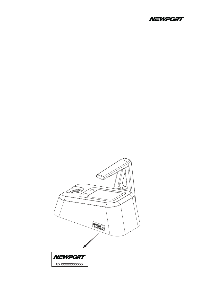
1.1 Product Identication
Check the gure below to nd the serial number of your product. You
will need this as a reference to access after-sale services.
Product Serial Number

6
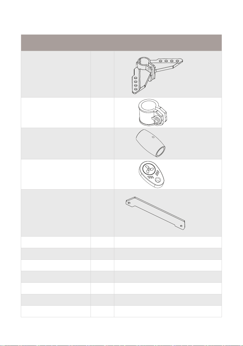
1.2 Included in Your Box
Here is what should be included in your Kayak Motor NK180. Please
contact us directly if something is missing from this list of contents.
Items Qty Figure
Motor Unit 1 pc
Controller 1 pc
Motor Mount 1 pc
7
Items Qty Figure
Steering Triangle 1 pc
Clamp Ring 1 pc
Cable Handle 2 pcs
Emergency Stop Key 2 pcs
Swing Arm 1 pc
S Biner 2 pcs
Stainless Biner 2 pcs
Battery Extention Cable 1 set
Nylon Cable 1 set
Steering Cable 1 set
Installation Kit 1 set
User Manual 1 pc
8
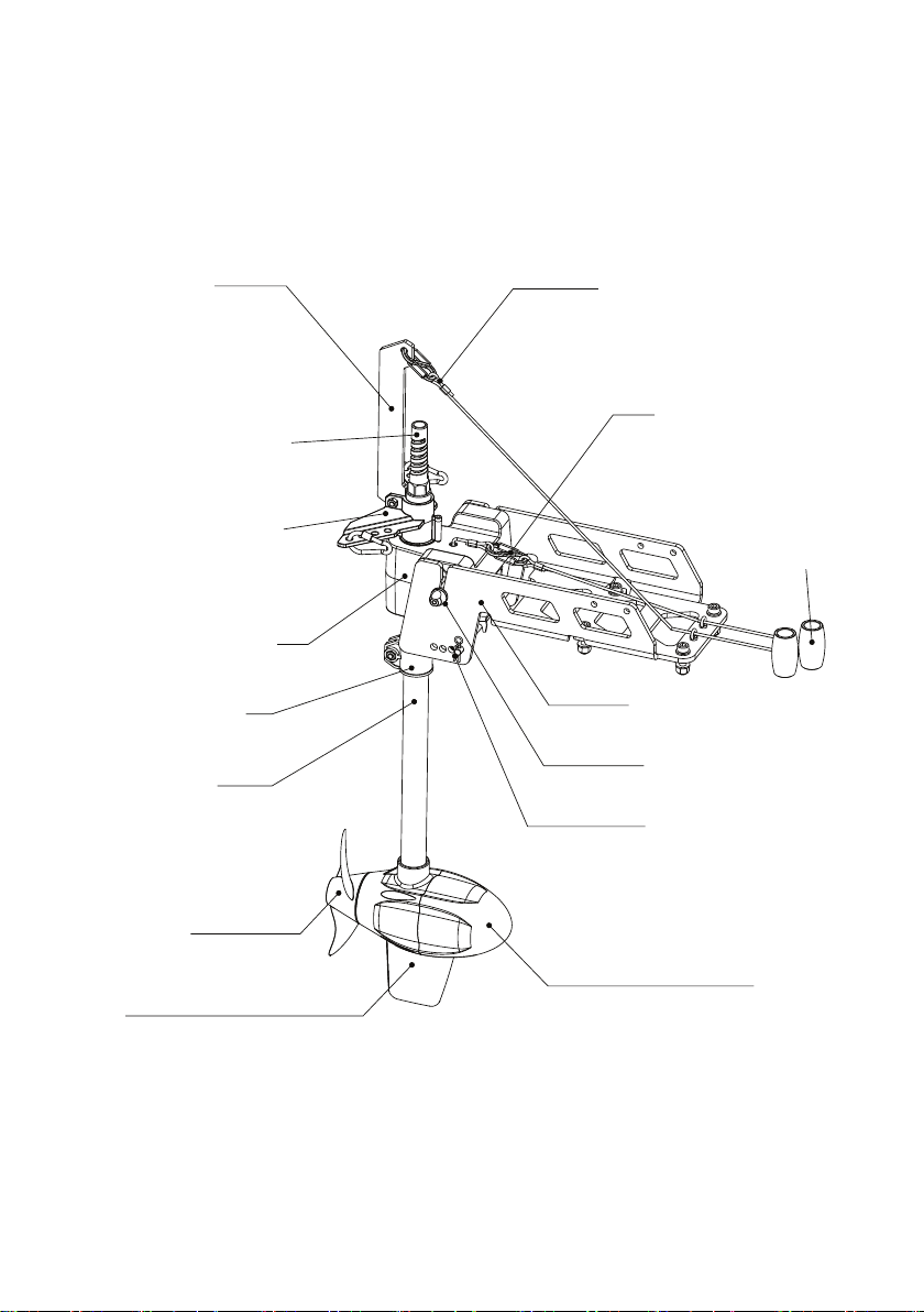
1.3 Parts and Diagrams
1.3.1 Motor and Bracket
S Biner and cord
for lifting the motor
S Biner and cord
for reverse lock
Handle
Battery and control
box connection
Swing arm
Steering triangle
Motor
supporting drum
Clamping ring
Motor shaft
Propeller
Fin
Motor
Aluminum bracket
Quick release
axle with handle
Trim mechanism
9
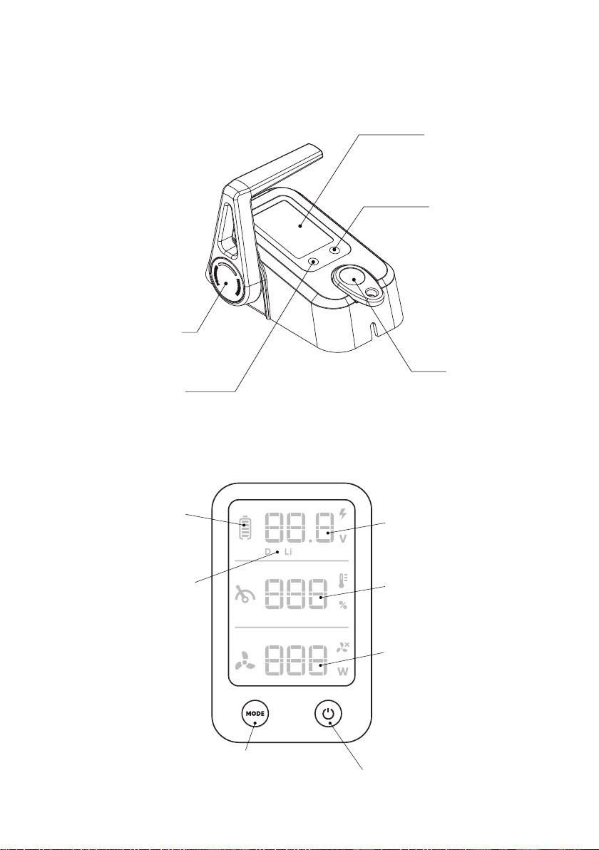
1.3.2 Speed Controller
1.3.3 Controller Screen Display
Accelerator lever
Battery type
selection button
Power button
Screen display
Emergency
stop key
Power input
display
Battery type
selection button
Power button
Battery type
display
Battery
percentage
display
Battery voltage
display
Throttle
percentage
display

10
2 Technical Data
Specication
Rated Input Power(static) 600W/25A
Comparable Petrol Outboard 1.8 HP
Battery Type
•Deep cycle marine battery
•LFP lithium battery
•Lithium cobalt oxide battery
Battery Input voltage
•24V-Deep cycle marine battery
•24V-LFP Lithium battery
•25.9V-Lithium cobalt oxide battery
Max. Overall Eciency 48%
Max. Propeller Rotational Speed 1800 rpm
Package Dimension(L-W-H) 31.5 x 15.4 x 6.3 in. (80 x 39 x 16 cm)
Total Weight 14.3 lbs (6.5kg)
Shaft Length 19.7 in. (50 cm)
Steering Cable steering
Control Method Digital control with accelerator lever
Stow Method Cable lift
Trim Angle 0°, 9°, 18°, 27°
Propeller Diameter 5.9 in. (15 cm)
Table of contents
Other Newport Engine manuals


