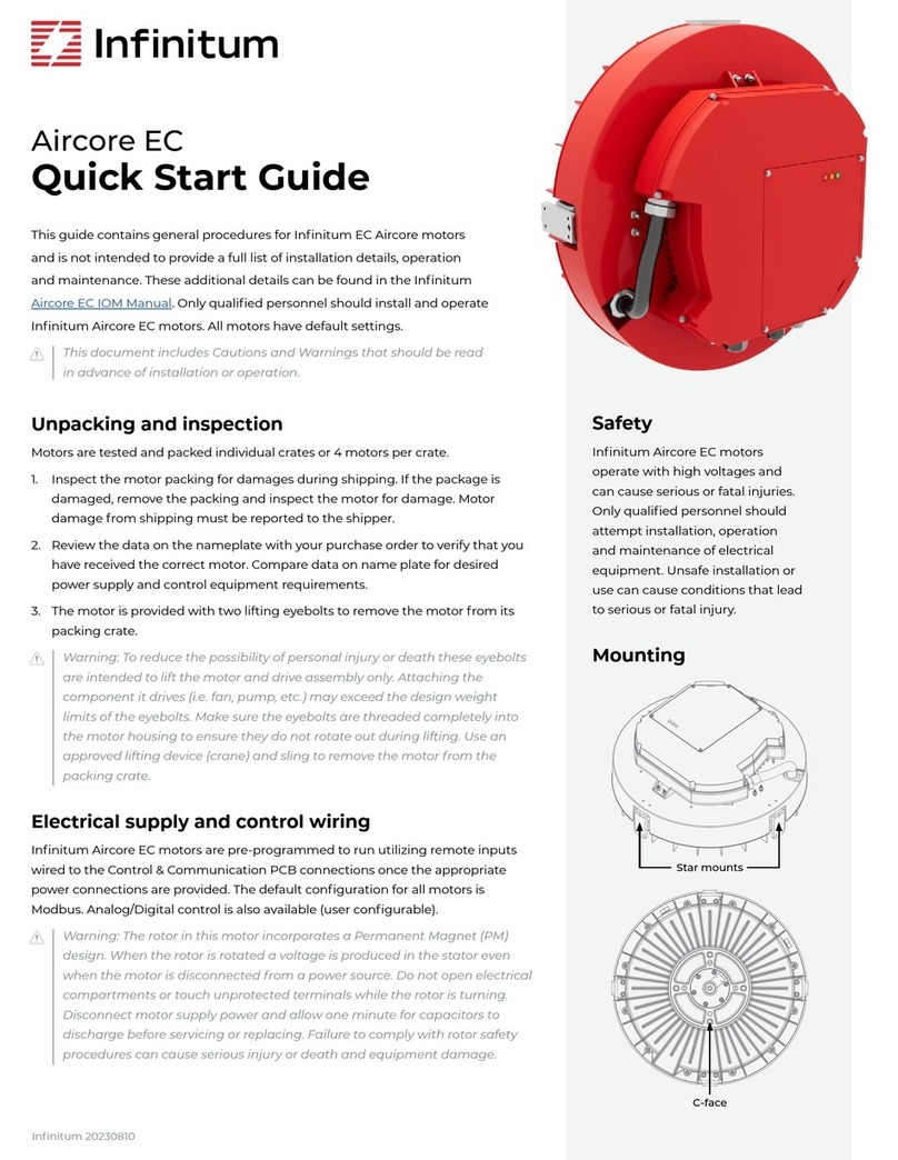
Infinitum Aircore EC Instruction manual

1
Infinitum 20230810 PRELIMINARY
Aircore EC
Installation, Operation
& Maintenance Manual

2
1. About the manual 3
a. Warnings, cautions and notes 3
2. Motor technology 3
a. Motor overview 3
i. Aircore EC motor technology 3
ii. Infinitum Aircore EC stator 3
iii. Aircore EC motor components 3
3. Receiving inspection 4
a. Packing inspection 4
b. Remove motor from container 4
c. Compare nameplate data 4
d. Rotate motor output shaft 4
e. Ready spare storage 4
i. Motor bearings 5
ii. Scheduled output shaft rotation 5
4. Motor installation 5
a. Preparation 5
i. Operating ambient temperature 5
ii. Ingress protection 5
b. Motor location 5
c. Motor orientation 6
d. Motor mounting and alignment 6
i. Mounting options 6
ii. Peripheral mounting block 6
iii. C-face mounting 6
e. Mounting and aligning motor 6
f. Minimum motor connection requirements 7
g. Motor control connections 7
h. Motor ground circuit verification 7
i. Connecting motor 7
j. Conductor size and terminal data 8
k. Circuit breaker and wire sizing 8
l. Control connections 9
m. Analog control wire guidelines 9
n. Modbus RTU wiring guidelines 9
o. AC main input connections 9
p. Check motor rotation 10
q. Connect motor to driven equipment 10
r. Default and user programmable settings 10
5. Motor maintenance 10
a. Maintenance tasks 10
b. Mechanical 10
6. Motor drive parameters and data types 10
Table of contents

3
Infinitum 20230810 PRELIMINARY
1. About the manual
a. Warnings, cautions and notes
Warnings, cautions and notes are throughout the manual to alert
the technician of potential hazard or process information. Below is
an explanation of the use.
Warnings: are safety related. Serious injury, death and
equipment damage can result if the instructions in the
warning are not followed.
Cautions: apply to conditions that can cause equipment
damage. If instructions in the Caution are not followed,
motor and associated equipment damage may occur.
Notes: The text of the note is Italicized. Notes add information
that can aid in the completion of a process or step.
2. Motor technology
a. Motor overview
Infinitum has developed a new generation of electric motors
with unparalleled efficiency and durability. We’ve reinvented
axial air-core motors using lightweight materials and a modular
design that generates the same power with less weight than a
legacy motor. These motors include on optimized VFD (Variable
Frequency Drive) for maximum performance and efficiency at a
wide operating range. Infinitum has an established ecosystem of
configuration software as well as optional IoT connectivity for real-
time monitoring and analytics. These motors are manufactured at
a fraction of the carbon footprint created by conventional motors.
It is designed with future generations in mind taking the entire
lifecycle into account creating a huge leap in sustainability.
i. Aircore EC motor technology
The introduction of the Aircore EC motor surpasses motors
utilizing standard technology and construction. Like all motors,
Infinitum machines have a stator, the stationary part and a rotor.
The rotating component Aircore EC motors have two rotors. In
traditional motors the stator is located in the body of the motor
and is usually made of iron cores with copper windings. This iron
and copper adds to the overall weight of the motor. Additionally,
the insulation on these coil windings degrades with heat and time
requiring maintenance or eventual replacement of the motor.
ii. Infinitum Aircore EC stator
The Aircore EC stator is a Printed Circuit Board (PCB) rather than
utilizing a heavy iron core and with copper windings. The Infinitum
motor is designed utilizing a PCB stator sandwiched between two
rotors (Figure 1). Permanent magnets are attached to the surface
of the two rotors. Since there is no iron in the magnetic path, the
motors can be classified as an air-core design.
iii. Aircore EC motor components
The PCB stator design allows for a smaller motor that weighs
significantly less than a conventional motor. Key components are
identified by the drawing in Figure 2.
Figure 2: Aircore EC motor components
Figure 1: Aircore EC stator
Direction of rotation
Rotor
Stator
Rotor
Access
cover
Drive
cover
Control
interface
module
VFD Drive
housing
Impeller Back
motor
housing
PCB
stator &
rotors
Mounting
pads
Front motor
housing
Bearing
Grounding
brush

4
Infinitum 20230810 PRELIMINARY
c. Compare nameplate data
• Compare data on nameplate with purchase order to verify
receipt of proper motor.
• Compare data on nameplate for desired power supply and
control equipment requirements.
d. Rotate motor output shaft
Warning: The rotor in this motor incorporates a Permanent
Magnet (PM) design. When the rotor is rotated a
voltage is produced in the stator even when the motor is
disconnected from a power source. Do not open electrical
compartments or touch unprotected terminals while the
rotor is turning. Disconnect motor supply power and allow
one minute for capacitors to discharge before servicing or
replacing. Failure to comply with rotor safety procedures
can cause serious injury or death and equipment damage.
Make sure all motor wire connections are properly terminated
and insulated. Turn motor rotor (output shaft) by hand. It should
turn freely with some drag from the bearing seals.
e. Ready spare storage
Motors purchased for ready spares are not placed into service
immediately. These motors should be stored in a clean, dry
space. Avoid spaces with large temperature swings to reduce
condensation. Storage temperature is -40 to 185 °F (-40 to 85 °C).
Cover motors to prevent airborne dust and dirt particles. If
storage area location is prone to vibration, place vibration
dampers under motor base to prevent premature wear and
damage to bearings.
Figure 3: Typical pallet
Figure 4: Lifting lugs
3/8-16 UNC THRU
(FOR LIFTING EYE BOLT)
3. Receiving inspection
Review and complete all appropriate sections prior to motor
installation. The motor is shipped in a robust container. The
container and motor can be moved by using a dolly, pallet jack or
fork truck (Figure 3).
a. Packing inspection
Inspect the motor packing for damages during shipping. If the
package is damaged, remove the packing and inspect the motor
for damage. Motor damage from shipping must be reported to
shipper.
b. Remove motor from container
Warning: The motor is provided with threaded holes for a
lifting lug. Lifting lugs may or may not be shipped with the
motor. (Figure 4). The lugs are intended to lift the motor
assembly only. Attaching the component it drives will
exceed the design weight limits. To reduce the possibility
of personal injury or death and equipment lift the motor
only, make sure the lugs are completely threaded into the
motor, and ensure they do not rotate out during lifting.
Lifting eye-bolts are M10x1.5t thread, 20mm shank or 1/2”-13
thread, 1 1/2” shank length, depending on motor. Consult the
appropriate drawing for that motor to be sure.
Warning: To reduce the possibility of personal injury and
equipment damage, only use a lifting device and straps
that are rated for the motor weight. Do not lift the motor
without mechanical assistance. Always inspect straps for
damages and weight certification prior to use.
Remove top of the packing crate and install the supplied lifting
lugs (Figure 3). Make sure the lugs are threaded completely into
the motor housing. Use an approved lifting device and sling to
remove the motor from the packing crate.

5
Infinitum 20230810 PRELIMINARY
i. Motor bearings
The bearings (Figure 5) used in this motor are lubricated and
sealed at the factory. The motor does not require bearing
lubrication in the field or during storage.
ii. Scheduled output shaft rotation
Warning: The rotor in this motor incorporates a Permanent
Magnet (PM) design. When the rotor is rotated a
voltage is produced in the stator even when the motor is
disconnected from a power source. Do not open electrical
compartments or touch unprotected terminals while the
rotor is turning. Disconnect motor supply power and allow
one minute for capacitors to discharge before servicing or
replacing. Failure to comply with rotor safety procedures
can cause serious injury or death and equipment damage.
Figure 5: Bearings
It is recommended the rotor (output shaft) be rotated five to ten
times per every quarter (three months). This distributes grease
in the bearings and reduces the chance of corrosion formation
on bearing rolling elements and raceways. Bearing seals can add
some resistance to turning the rotor.
4. Motor installation
a. Preparation
Review this entire manual prior to scheduling the motor
installation. All equipment related to systems operation must be
secured and have an active LOTO (Lock Out Tag Out) procedure
in accordance with application specific safety policies. All users of
should be notified of equipment outage.
i. Operating ambient temperature
The ambient temperature of the air supplied to the motor cooling
inlet should not exceed 40° C (104° F) or be less than -25° C (-13° F).
Power can be derated at higher temperatures by 2% per degree
C up to 50° C. Consult Infinitum for ambient temperatures not
within these requirements.
ii. Ingress protection
Infinitum motor Ingress Protection (IP) ratings are identified by
their respective nameplates. To maintain this IP rating, cable
glands or seals must be used at all wiring ports and all gaskets in
place with covers.
b. Motor location
Warning: This motor is not certified to operate in any
hazardous environments. Operating a motor in areas
contaminated with explosive gases can cause explosions
resulting in serious injury or death and equipment damage.
Electric motors have guidelines for the location and operating
environment. These guidelines are listed below:
• The motor should be located in a ventilated enclosure and
should be in an area that allows air circulation.
• Air cooling inlets and outlets must not be obstructed.
• The enclosure cannot be located in an area with harmful or
explosive gasses.
• The area should be free from dust and metallic particles.
• The motor should be easily accessed for cleaning and
maintenance.
• The motors are intended for indoor applications.

6
Infinitum 20230810 PRELIMINARY
c. Motor Orientation
Gen4 Aircore EC motors can be used in any orientation,
horizontal, shaft up or shaft down.
d. Motor mounting and alignment
The Aircore EC motor system is supplied with an integrated VFD.
The motor and drive are the major components of the assembly.
Refer to motor datasheets for detailed dimension drawings.
i. Mounting options
Driven equipment (for example, a fan wheel) should be mounted
to the shaft using as much of the available shaft length as
possible. A shaft key-way and shaft key are provided for secure
coupling of hubs to the shaft.
There are two mounting options for the motor, peripheral
mounting or C-face mounting.
ii. Peripheral mounting block
There are four mounting blocks on the surface of the motor,
spaced at 90º intervals. Each block has provisions for a lifting lug
that can be used to lift the motor, and mounting holes at the
drive end (DE) face and transverse surface.
The transverse face of the mounting block has threaded holes for
four mounting bolts. All four mounting bolts should be installed
for secure motor mounting. See the respective motor diagram for
a its mounting hole pattern in Figure 6.
iii. C-face mounting
Infinitum Aircore EC motors are not a NEMA standard frame size
but utilize a NEMA 182TC faceplate mounting configuration.
The DE face of the mounting block has threaded holes for four
bolts (M8X1.25). All bolt holes should be used for secure mounting
of the motor to equipment (Figure 7).
Caution: Use care when installing the driven equipment
onto the rotor shaft. Do not force the hub or coupling onto
the shaft since this may damage the motor bearings. If the
hub or coupling does not slide without resistance, check
alignment of the equipment with the rotor shaft.
Maintain adequate clearance between the front of the motor
body and the equipment to prevent mechanical obstruction that
may cause damage or injury.
The motor and stator assembly must be mounted on a structure
that will support the operational weight of the motor. Use
vibration dampers at motor assembly mounts to reduce motor
vibration. Align the stator output shaft centerline with the driven
component and install mounting hardware but do not tighten.
This is completed with the alignment process.
Figure 6: Circumference mounting pads and shaft keyway
4x Mounting pads
Figure 7: DE face
4x C-face mounting
e. Mounting and aligning motor
The motor may be directly mounted to equipment such as fan
wheels or may be connected through a belt or pulley system.
It may also be attached through a shaft coupling, e.g., to an
independently mounted pump, or to a torque meter in a
laboratory setting. Ensure proper alignment is maintained in all
arrangements.
Use driven equipment manufacturer’s recommendations for
aligning the motor with the fan drive or coupling. Tighten all bolts
and nuts on the motor mount.
Motor rotation must be verified after electrical connection.
Incorrect rotation can damage equipment.

7
Infinitum 20230810 PRELIMINARY
f. Minimum motor connection requirements
Warning: Always disconnect power to the motor and
practice all application specific safety procedures when
installing, troubleshooting, or repairing a motor. Always
verify power is secured with a multimeter prior to work.
Failure to disconnect power from motors can result in
serious personal injury or death and equipment damage.
Warning: The rotor in this motor incorporates a Permanent
Magnet (PM) design. When the rotor is rotated in a
disconnected motor voltage is produced. Do not touch
unprotected terminals while the rotor is turning. Disconnect
motor supply power and allow one minute for capacitors to
discharge before servicing or replacing. Failure to comply
with rotor safety procedures can cause serious injury or
death and equipment damage.
Warning: To reduce the possibility of personal injury or
death and equipment damage, always make sure wire
connections are secure and wires are in the correct location.
Caution: To prevent the possibility of motor damage, always
use terminating ferrules for all supply wires. Terminating
ferrules create a single connection point that is more secure
than stranded wire.
Wire tensile forces can affect the point of termination during
installation and motor operation. Terminal blocks with the correct
wiring installed ensure safe motor operation. Using the correct
wire gauge and amount of exposed conductor length with ferrules
installed on each wire satisfies the requirements.
Make sure the source of power to the motor has been
disconnected.
Strip wires and crimp on wire ferrules. Install each wire into the
appropriate terminal block as provided in the wiring instructions.
Verify all connections are tight and installed to specifications.
NEC 70 and NEMA MG2 standards should be followed for proper
motor power wiring.
g. Motor control connections
Infinitum Aircore EC motors support standard industry control
methods. The following are supported:
• Analog/Digital
• Modbus RTU
• Modbus TCP
Infinitum also supplies proprietary configuration and control
software known as I-con (motor control software).
h. Motor ground circuit verification
Warning: Motors must be properly grounded. Adhere to all
guidelines when installing the motor ground circuit. Failure
to ground a motor can cause personal injury, death, and
equipment damage.
It is advised to conduct resistance readings with a multimeter on
the motor ground circuit. Never apply power to a motor that does
not have a complete ground circuit.
i. Connecting motor
Each of the circuit boards and housing components has a
separate design function. Only two of the circuit boards have
user inputs. The main circuit boards and connection points are
highlighted in Figure 8.
1. Power board: Connections for three-phase supply. Rectifiers
convert AC to DC for internal use on this board.
2. Communication interface module (CIM). This circuit board
contains advanced controls and communications.
3. AC Input: Ground terminal is in chassis. (Figure 10)
Figure 8: Main motor boards
3
2
1
AC input
Power board
Communication
Interface Module
Note: Safety cover removed for illustration purposes.

8
Infinitum 20230810 PRELIMINARY
j. Conductor size and terminal data
Board Terminals
Maximum conductor size Exposed
conductor
length
Terminal type
mm^2 AWG
Communication interface module Control terminals 1.3 16 8 mm Spring terminal
Power board AC Mains-U, V & W 5.2 / 3.3 10 / 12 12 mm Spring terminal
Screw terminal Earth ground 1.6 14 12 mm Lug and screw
Max torque 2 Nm
k. Circuit breaker and wire sizing
Fuses or breakers should be used to provide protection
for the input power cables. These should be installed
in the incoming supply lines according to Table 1
(below). UL listed non-time-delay type T or RK1 fuses are
recommended. Type B circuit breakers of equivalent
rating to the fuses may be used. Other fuse or breaker
types may be acceptable. Fuses and breakers should
comply with any local codes or regulations.
The input wiring should be sized based on the current
requirements of the motor. The connector minimum
and maximum wire sizes are included in Table 2.
The maximum permissible short circuit current at the
drive input power terminals is 5kA.
Table 1: Breakers and fuses (3-phase 480V AC (+/- 10%) – 3-phase 460V output)
Power (HP) Rated Current (A) UL Fuses (Class T or RK1)
or UL Type B Breakers
Minimum Suggested
Wire Size (AWG)
56.0 10 16
7.5 9.0 15 16
10 12.0 15 14
15 18.0 25 12
Table 2: Terminal connection data
min. max.
Rigid cable cross-section 0.2 mm² 6 mm²
Flexible cable cross-section 0.2 mm² 6 mm²
Cross section AWG 24 10
Wire-end ferrules (w/insulating collar) 0.2 mm² 4 mm²

9
Infinitum 20230810 PRELIMINARY
l. Control connections
Remove the VFD cover for access to Analog/Digital and
Modbus connections.
1. Relay (1) – NO/NC (COM must be used)
• Max voltage: 125 VAC / 30 VDC
• Max current: NO-10A VAC, 5 A
• VDC: NC – 3A VAC or VDC
2. Digital input (4) – DIN1, DIN2, DIN3 & DIN4
3. Digital output (2) – DO1 & DO2.
• Open drain output
• Maximum switching voltage 40 VDC
• Maximum switching current 350 mA
4. Auxiliary Voltage (1) +24v (GND must be used)
Warning: (Do not exceed 24V on this input)
5. Analog output (1) – A_OUT (GND must be used)
6. Analog input (1) – A_IN (GND must be used)
7. EIA-485 interface (1) – 485_P & 485_N (GND must be used)
Note: Use wirenut to connect shield wires. Do not tie to GND.
8. Modbus termination switch. (Default is Off)
9. RJ45 for I-con (motor control software) connection
Terminals on the interface board (Figure 9) feature push-
button spring clips. The push-button on each terminal must be
depressed while inserting the wire. Releasing the push-button
clips the wire into place.
m. Analog control wire guidelines
To control the unit using Analog control please utilize the wiring
guidelines on the CIO board (Figure 9).
Caution: DIN1-DIN4 are limited to 24VDC input. AI1 is
rated 0-10V @ 100mA max. Exceeding these voltages will
permanently damage the communication board. Do not
insert external wiring larger than 16 AWG (0.05” or 1.3mm)
into control terminals.
Start/Stop
switch
Modbus RTU
Wiring
Analog control
Modbus RTU
1
2
3
4
5
6
7
Figure 9: CIM board
n. Modbus RTU wiring guidelines
To control the motor with Modbus RTU please utilize the wiring
guidelines to connect to the Communication I/O (Figure 9).
• The last unit on a daisy-chain configuration should have the
Modbus Termination DIP switch “ON”.
• All other units must have the DIP switch in the “OFF” position.
• Modbus RTU operation requires changes to the motor
configuration parameters.
o. AC main input connections
The AC main inputs (Figure 10) are on the power board.
The supply voltage connections are:
1. Supply voltage phase A
2. Supply voltage phase B
3. Supply voltage phase C
The AC input terminals feature spring clips. The orange tab must
be raised to insert the wire. Closing the orange tab secures the wire
into place.
The grounding post is located off the power board on the
chassis itself.
9
8
Figure 10: AC main input
L1 L2 L3
Grounding post
NC
NO
COM
DIN4
DIN3
DIN2
DIN1
DO2
DO1
GND
+24V
GND
A_OUT
GND
A_IN
GND
485_P
485_N
GND
0-10V Speed
Signal
Power board

10
Infinitum 20230810 PRELIMINARY
We reserve the right to make technical changes or modify the contents of this document
without prior notice. Copyright© 2023 Infinitum Electric, Inc. All rights reserved.
106 Old Settlers Blvd
Suite D106
Round Rock, TX 78664
info@goinfinitum.com
goinfinitum.com
support.goinfinitum.com
Office Contact
p. Check motor rotation
Note: If the motor has been tested and the technician has
verified motor rotation prior to installation, the facility can elect
not to perform this test because of redundancy.
Prerequisites: The motor has been installed, aligned and
electrically connected. The fan belt is removed, or coupling is
disconnected. The motor must be briefly energized to check for
proper rotation.
Steps are outlined below:
1. Review all installation instructions and all warnings prior to
testing the motor.
2. Connect AC power
3. Follow all safety precautions and energize the motor briefly to
determine rotation. If the motor rotates opposite of intended
direction, switch the direction command utilizing I-con
software tool.
4. Disconnect AC power.
q. Connect motor to driven equipment
Warning: Always disconnect power and practice all safety
procedures when installing, troubleshooting, or repairing
a motor. Always verify power is secured with a multimeter
prior to work. Failure to adhere follow industry standard
safety practices can result in serious personal injury or death
and equipment damage.
Prerequisite: Motor rotation has been verified. The final series of
steps will place the load on the motor and test system operation.
Steps outlined below:
1. Disconnect power from the motor
2. Attach driven equipment confirming alignment
3. Install all safety covers and connect power
4. Start the system and verify the motor operates properly.
r. Default and user programmable settings
Infinitum EC Aircore motors are shipped with factory default
settings for maximum speed, control methods and other values.
To change your motor’s settings, download the I-con software.
5. Motor maintenance
a. Maintenance tasks
This motor requires inspections and tasks be completed on a
Quarterly (3 months) basis or 500 hours whichever occurs first.
Maintaining this motor requires completion of both inspection
and tasks. Review above warnings. The basic tasks are outlined
below:
1. Disconnect motor line power and all associated operating
equipment and allow one minute for motor capacitors to
discharge.
2. Examine driven equipment for looseness or damage.
3. Inspect the motor output shaft for damages. Replace
damaged components and tighten any loose set screws.
4. Make sure the cooling fins and area around the motor are free
from dust and debris.
5. Make sure the mounting bolts and hardware are tight and
secure.
6. If used, check rubber vibration isolators for cracks and damage.
7. Make sure all wire connections are tight.
8. Inspect internal wires for signs of heat damage.
Any damages noted must be repaired before placing the motor
into service.
b. Mechanical
Problems with alignment can cause bearing wear. Lack of
maintenance, improper installation, and loose mounting bolts can
cause premature bearing wear and motor overloads.
6. Motor drive parameters and data types
The Aircore EC motor parameters can be found here.
Other manuals for Aircore EC
2
Table of contents
Other Infinitum Engine manuals
Popular Engine manuals by other brands
BAFANG
BAFANG H400 Dealer's manual
Ametek
Ametek dunkermotoren BG 66x25 dMove Translation of the original function and connection guide
WPT POWER
WPT POWER PILOTLESS Installation & maintenance manual

BONFIGLIOLI
BONFIGLIOLI BMS series Installation use and service manual

Volvo Penta
Volvo Penta TAMD103A Operator's manual
Maco
Maco HAUTAU SA 650N Mounting and operating instructions
