Newport 244/1409 User manual

MADE IN
BRITAIN
Dimensions
Width - 70.5cm
Depth - 50cm
Height - 172cm
Newport - 2 Door Robe
Assembly Instructions - Please keep for future reference
If you need help or have damaged or missing parts, call the Customer Helpline: 03456 400800
Issue 4 - 19/01/15
Important - Please read these instructions fully before starting assembly
ALR3052
244/1409
258/8403
Issue 2 - 28/07/14 - The backslash was missing from the 2nd cat code.
Handles were splitting using 2 screws and are now fitted with just 1 screw.
Issue 3 - 30/09/14 - Added shelf support drillings to Right Side so it can alsobe used on the 3 Door Robe.
Right Side updated to DF286B.
Issue 4 - 19/01/15 - Overbalance Bracket replaced woth Strap Kit.
Updated helpline number.

Safety and Care Advice
Important - Please read these instructions fully before starting assembly
• Warning: This unit weighs
approximately 38.5kgs.
Please lift with care.
• Check you have all the
components and tools listed on
pages 2 and 3.
• Remove all fittings from the
plastic bags and separate them
into their groups.
• Keep children and animals
away from the work area, small
parts could choke if swallowed.
• Parts of the assembly will be
easier with 2 people.
• Make sure you have enough
space to layout the parts before
starting.
• Do not stand or put weight on
the product, this could cause
damage.
• Assemble the item as close to
its final position (in the same
room) as possible.
• Assemble on a soft level
surface to avoid damaging the
unit or your floor (use opened
out unit carton).
1
Care and maintenance
• Only clean using a damp cloth
and mild detergent, do no use
bleach or abrasive cleaners.
• From time to time check that
there are no loose screws on
this unit.
• This product should not be
discarded with household
waste. Take to your local
authority waste disposal centre.
Note: If required the next page
can be cut out and used as
reference throughout the
assembly. Keep this page with
these instructions for future
reference.
• We do not
recommend the
use of power
drill/drivers for
inserting screws,
as this could damage the unit.
Only use hand screwdrivers.
• Safety note: It is
recommended that this unit is
secured to a wall using the
overbalance protector kit
supplied or, an alternative fixing
method of your choice.
• Dispose of all packaging
carefully and responsibly.
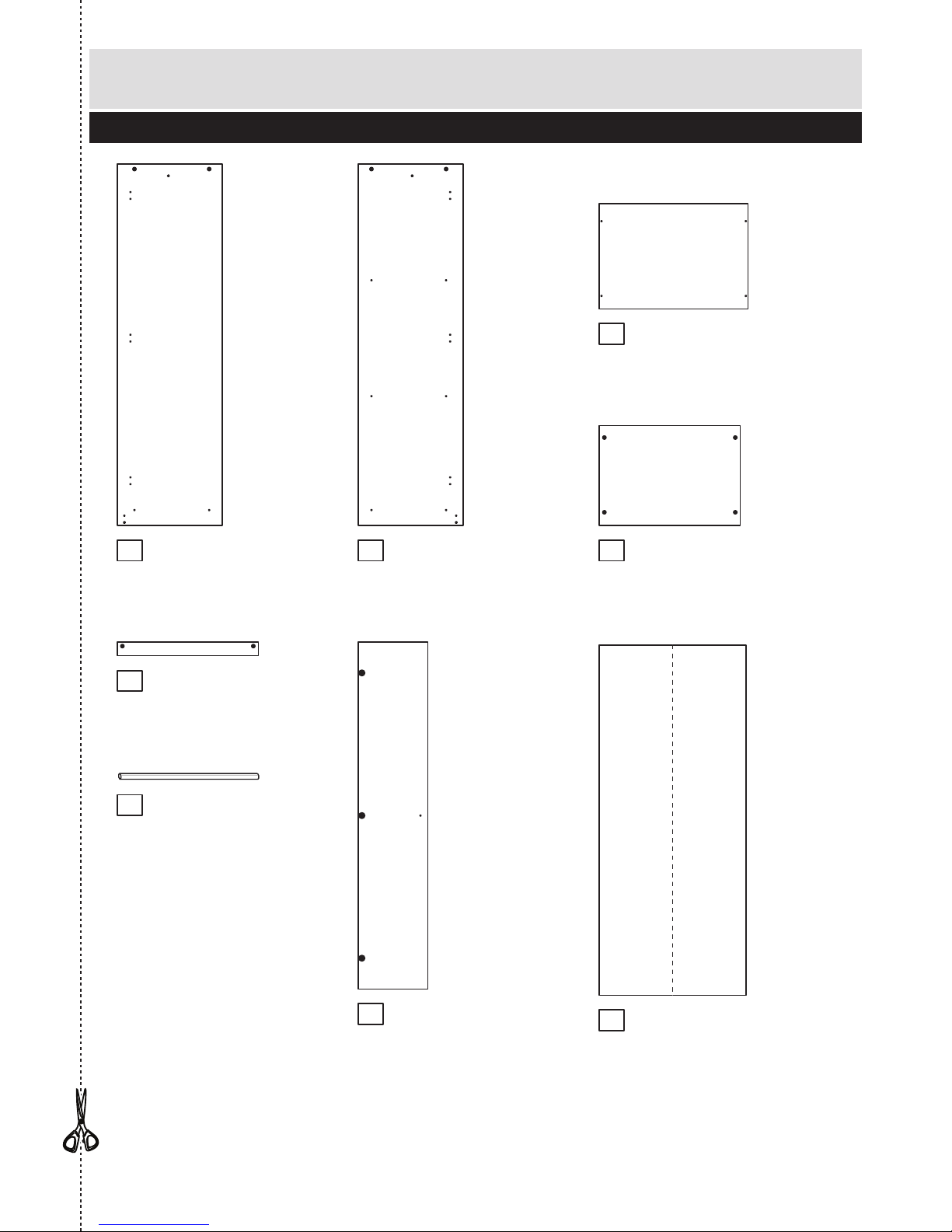
Components - Panels
Please check you have all the panels listed below
2
12 4
80%
x 3
If you have damaged or missing components, call the
Customer Helpline: 03456 400800 quoting the reference
numbers below
Door (DF288B)
(1635 x 328mm) x 2
Left End (DF285)
(1703 x 495mm)
Top (DF287)
(701 x 496mm)
Plinth (DF290)
(665 x 65mm)
Base (DF291)
(665 x 470mm)
5
3
78
Hanging Rail (FHR657)
(657mm long)
6
Back (X1650-691)
(1650 x 691mm)
Right End (DF286B)
(1703 x 495mm)

Please check you have all the fittings listed below
Tools required
3
Components - Fittings If you have damaged or missing components, call the
Customer Helpline: 03456 400800 quoting the reference
numbers below
Note: The quantities below are the correct amount to complete the assembly. In some cases
more fittings may be supplied than are required.
A
Wooden dowel (F22) x 2
B
Metal dowel (F901) x 10
C
D E F
G H I
Ruler - Use this ruler to help correctly identify the screws
mm 10 20 30 40 50 60 70 80 90 100 110 120 130 140 150 160 170
25mm Screw (F50) x 2
Nail (F51) x 32 Plastic Nail (F91) x 4
Rule Scissors Hammer
Eye protection
(when using a
hammer or drill)
Cross-head
screwdriver
Electric drill
(do not use for
fitting screws)
JK
Large locking
nut (F900) x 10
13mm Screw (F63) x 14
Handle (F314) x 2
Rail holder
(F1014) x 2
L
Hinge (F520) x 6
Hinge Plate
(F521) x 6
Strap Screw Washer x 2
Overbalance protector kit (F269) x 1

C
Finished
front edge
Assembly Instructions
4
If you have damaged or missing components, call the
Customer Helpline: 03456 400800 quoting the reference
numbers below
Step 1
Step 2
J
J
J
J
J
Prepare the left side
Screw 3 metal dowels
into the left side .
Note: Tighten the metal
dowels up fully against
the panels.
Insert 2 large locking
nuts into the
left side .
Note: The arrow on the
locking nut must point
towards the hole in the
edge of the panel.
Fit 3 hinge plates to
the left side making
sure that the slot is
facing towards the
finished front edge.
Push a rail holder into
the left side . Make
sure that it is fitted
straight, in line with the
panel edges and then
secure with screw .
B
1
B
C
C
C
I
F
BB
C
1
1
J
1
J
J
J
BB
B
C
I
F
Prepare the right side
Screw 3 metal dowels
into the right side .
Insert 2 large locking
nuts into the
right side .
Fit 3 hinge plates to
the right side making
sure that the slot is
facing towards the
finished front edge.
Push a rail holder into
the right side and
secure with screw .
B
2
C
2
2
J2
I
F
1
I
F
1
Finished
front edge
This manual suits for next models
1
Table of contents
Other Newport Indoor Furnishing manuals


Popular Indoor Furnishing manuals by other brands

Regency
Regency LWMS3015 Assembly instructions

Furniture of America
Furniture of America CM7751C Assembly instructions

Safavieh Furniture
Safavieh Furniture Estella CNS5731 manual

PLACES OF STYLE
PLACES OF STYLE Ovalfuss Assembly instruction

Trasman
Trasman 1138 Bo1 Assembly manual

Costway
Costway JV10856 manual


