Newport e360 User manual

Newport Medical Instruments, Inc.
Newport e360 Ventilator
Operating Manual
For Model e360S-US
OPR360US Rev. H
07/11
0344
Newport Medical Instruments, Inc.
1620 Sunflower Ave.
Costa Mesa, CA 92626
Tel: 1.714.427.5811
Tel: 1.800.451.3111 (USA Only)
Fax: 1.714.427.0489
Customer Service ext. 282
www.ventilators.com
email: Info@ventilators.com

Rev A April 2004 New release
Rev B July 2006 Update to software USR1.1
Rev C February 2008 Update company logo and remove
CE/EU representative information
Rev D March 2008 Update manual to include Addendum
Document (DOC360-ADD-4-US) for
software release USR3.1
Rev E May 2008 Update manual to replace Addendum
Document (DOC360-ADD-4-US)
Revision A with Revision B for
software release USR3.1B, which also
includes any updated information
before the USR3.1B
Rev F December 2009 Updated manual to incorporate
DOC360-ADD-4-US, reformatted
to new compact size, added
drawings and streamlined
content. Current to software USR3.8
Rev G June 2011 Operating Manual Revision Notice
included for update to internal battery
recharge schedule, added patent
number and update to warranty for
O2sensor.
Rev H July 2011 Update manual to include Software
version 7.0 new features: NIF & P0.1
maneuvers, O2sensor disable &
FlexCycle feature. Correction to O2
sensor warranty.
OPR360U A0509
5-1
5
OPR360U A0509
5-1
5
OPR360US H0711
Manual Revision History

OPR360U A0509
5-1
5
OPR360U A0509
5-1
5
OPR360U A0509
5-1
5
OPR360US H0711
Contact Information
Telephone: +1.714.427.5811 or 1.800.451.3111 (US only)
Fax: +1.714.427.0489
Customer Service: ext: 282
Hours: Monday through Friday, 8:00 am to 5:00 pm (PST)
24 hour Support:
Technical Support: ext. 500
Clinical Support: ext. 123
Email:
Customer Service Department: customers@ventilators.com
Clinical Education and Support: clinical@ventilators.com
Technical Service and Support: techservice@ventilators.com
Internet: www.ventilators.com
Shipping Address:
Attn: Receiving Dept.
1620 Sunflower Avenue, Costa Mesa, CA 92626 USA
EC Representative: EC REP
Newport Medical Instruments, Inc.
Attn: Robert Brink
C/O Braun & Co.
11B/11C Harrier Road
Humber Bridge Industrial Estate
Barton-on-Humber, North Lincolnshire
DN18 5RP, England
Tel: +44.1652.632273
Fax: +44.1652.633399
Copyright Information
© Copyright 2011 Newport Medical Instruments, Inc. All rights
reserved. The Newport e360 Ventilator system is manufactured in
accordance with Newport Medical Instruments, Inc. proprietary
information. The Newport e360 is covered under patent # 6,439,229.
The information in this manual is the sole property of Newport
Medical Instruments, Inc. and may not be duplicated without
permission. This manual may be revised or replaced by Newport
Medical Instruments, Inc. at any time and without notice.

OPR360US H0711
Figure F-3: GUI Navigation Map
Figure F-2: Newport e360 Rear Panel
1
2
3
4
5
6
7
Oxygen Inlet
Air Inlet
Remote Alarm Connection
Alarm Speaker
External Alarm Silence
On/Off Power Switch
RS232 Connection
8
9
10
11
12
13
14
VGA Connection
USB Connection
Cooling Fan
Equipotential Ground Stud
AC Power Connection
Fuse Drawer
External Battery Connection

OPR360US H0711
Check
power on). Do not use a test lung to block the patient wye for the circuit check
test.
ADULT
VTPC-SPONT
05-01-2008 15:30
Hours
999999.7
Int
Bat
*

OPR360U A0509
5-1
5
OPR360U A0509
5-1
5
OPR360US H0711
Table of Contents
1 Introduction
Device Description
Intended Use Information
About this Manual
Typing Conventions
Software Versions
Service Guidelines
Regular Service
Complete Service Records
Disclaimers
Warnings
General Warnings
Filter Warnings
Power Supply Warnings
Gas Warnings
Auxiliary Equipment Warnings
Cautions
Warranty Information
Responsibility for Patient Safety
Limitation of Liability
2 Overview
Ventilator System Overview
Control Panel Layout and Labeling
Graphical User Interface (GUI) and Controls
Navigation Map for GUI Menus
Lower Front Panel Layout
Rear Panel Layout
Navigating the Control Panel
Using Touch-Turn-Accept
Selecting Mandatory Breath Type and Mode
Non Invasive Function
Patient Triggering Methods
Basic Ventilation Controls
Flow or Insp Time in Volume Control
Manual Inflation Button
O2 3 Minute Button
Alarm Silence Button
Suction Disconnect Function
Alarm Reset
Graphical User Interface (GUI) Screens
Alarms Screen
Main Screen
Extended Functions Screen
Setup & Calibration Screen
GUI Miscellaneous Indicators
Internal Battery

OPR360U A0509
5-1
5
OPR360U A0509
5-1
5
OPR360U A0509
5-1
5
OPR360U A0509
5-1
5
OPR360US H0711
Table of Contents
3 Unpacking, Assembly, and Safety Check
Unpack the Ventilator
List of Package Contents
Assembly
Exhalation Valve Compartment
Connect Air, Oxygen and AC Power
Install the Breathing Circuit System
Safety Check Procedure
Setup and Inspection
Emergency Intake Valve
Circuit Check
Gas Supply Alarms
AC Power Loss/Battery Backup Alarm
High/Low Airway Pressure Alarm/Circuit Disconnect Alarm/
Alarm Silence
Minute Volume/Back Up Ventilation/Apnea Alarms
Trigger/Pressure Support
Volume/Flow/Rate Accuracy Test
Shut Down Alarm
Safety Check Record Sheet
4 Setting Up for Patient Use
Power Conditions
Shutdown Alarm
Overview: Preparing for Patient Ventilation
Setup & Calibration Menu
Circuit Check
Oxygen and Flow Sensors
Exhalation Flow Sensor, Calibration
Oxygen Sensor, Calibration
Oxygen Sensor, Disable
Patient Setup
Patient Category
Weight Units
Ideal Weight
Volume Units
Sigh
Circuit Type
Leak Comp (Leak Compensation)
Compl Comp (Compliance Compensation)
Technical
Comm (Communications) Protocol
Display Brightness
Regional Settings
Altitude
Date Format
Date and Time

OPR360U A0509
5-1
5
OPR360U A0509
5-1
5
OPR360U A0509
5-1
5
OPR360U A0509
5-1
5
OPR360US H0711
Table of Contents
Screen Files
Event History Files
Ventilator Controls Guide
Ventilator Settings in Advanced Data Set
Slope/Rise
Expiratory Threshold
Pause
Flow Waveform
Volume Target
Open Exhalation Valve
Inspiratory and Expiratory Hold Maneuvers
P0.1 Measurement Function
Negative Inspiratory Force (NIF) Maneuver
Waves and Loops Display
Adjusting Scale
Auto Scale
Using the Freeze Function
Using the Cursor in Freeze
Event History Screen
Numerics Screen
Trends Screen
Data Sets
Save Feature
Download Feature
5 Alarms
Introduction
Visual Alarm Displays
360° Alarm Lamp
Alarm and Message Display
Device Alert LED
GUI Alarm Screen Environment
Alarm Settings Screen
Saving the Alarm Settings Screen
Adjustable Alarms
Alarm History
Saving the Alarm History Log
Alarm Loudness
Alarm Tones
Exiting Alarm Screens
Front Panel Alarm Interface Environment
Alarm Silence Button
Suction Disconnect Feature
Alarm Reset Button
Non-Adjustable Alarms
Alarm Violation and Remedy Guide

OPR360U A0509
5-1
5
OPR360U A0509
5-1
5
OPR360U A0509
5-1
5
OPR360U A0509
5-1
5
OPR360US H0711
Table of Contents
6 Cleaning and Maintenance
Introduction
Use of Filters
Inspiratory (To Patient) Port
Expiratory (From Patient) Port
Disassembly and Reassembly Procedures
Rear Panel Fan Filter
Exhalation Manifold
Exhalation Flow Sensor
Exhalation Valve
Inspiratory Manifold
Oxygen Sensor
Fuses
Cleaning
Sterilizing
Autoclave Sterilization
EtO Sterilization
Guide to Cleaning and Sterilizing
Guide to Preventive Maintenance
Storing the Ventilator
Repackaging the Ventilator
7 Explanation of Modes, Breath Types and
Special Functions
Introduction
Settings Functions
Timing Limitations to Ventilation Controls
Control Retention
Control Range
Mandatory Breath Types
Volume Control
Pressure Control
Biphasic Pressure Release Ventilation
Volume Targeted Pressure Control
Spontaneous Breath Management in SIMV and SPONT
Pressure Support
Volume Targeted Pressure Support
Ventilation Modes
A/CMV
SIMV
SPONT (Spontaneous)
Advanced Features and Special Functions
Bias Flow
Slope/Rise
Expiratory Threshold and FlexCycle
Leak Compensation

OPR360U A0509
5-1
5
OPR360U A0509
5-1
5
OPR360U A0509
5-1
5
OPR360U A0509
5-1
5
OPR360US H0711
Table of Contents
Compliance Compensation
Non-Invasive Ventilation-NIV
Leak Compensation in NIV
Alarms Settings in NIV
8 Specifications
Alarms, Controls, Monitored Data, Setup & Calibration
Physical Specifications
Foldout Diagrams
Front
F-1 e360 Ventilator System and Accessories
F-2 e360 Rear Panel
F-3 Graphical User Interface (GUI) Navigation Map
F-4 Control (Front) Panel
F-5 Circuit Check Screen
Rear
F-6 Main Screen
F-7 Extended Functions Screen
F-8 Alarms Screen
F-9 Event History Screen
F-10 Technical Screen
F-11 Patient Setup Screen

Introduction
Section 1:
Introduction

OPR360U A0509
5-1
5
OPR360U A0509
5-1
5
Device Description ................................................1-1
Intended Use Information ............................1-2
About this Manual ..................................................1-2
Typing Conventions................................................1-3
Software Versions................................................. 1-4
Service Guidelines ............................................... 1-4
Regular Service ........................................... 1-4
Complete Service Records ........................ 1-4
Disclaimers ........................................................... 1-4
Warnings ........................................................1-5
General Warnings .........................................1-5
Filter Warnings ............................................. 1-6
Power Supply Warnings ...............................1-7
Gas Warnings ............................................... 1-8
Auxiliary Equipment Warnings ................... 1-8
Cautions ................................................................. 1-8
Warranty..................................................................1-9
Responsibility for Patient Safety ........................1-10
Limitation of Liability ........................................... 1-11
Introduction
Section 1:

OPR360U A0509
5-1
5
OPR360U A0509
5-1
5
OPR360US H0711 1-1
Introduction 1
Device Description
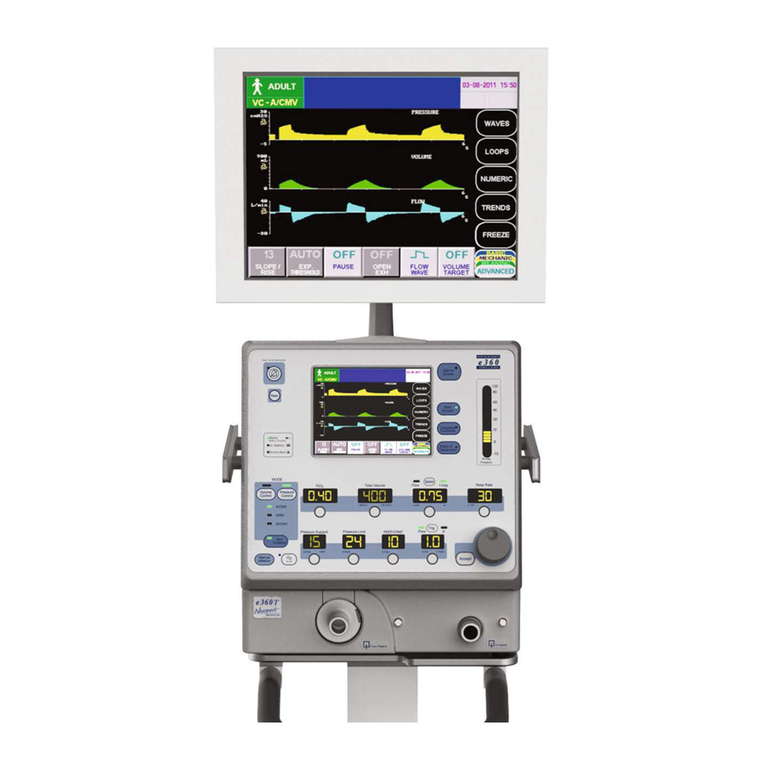
The e360 Ventilator is a high performance ventilator that is easy to use
and maintain. The e360 features a dual servo gas delivery system, a
servo controlled active exhalation valve, a simple to use interface and
a touch screen graphics monitor. The electronically-controlled inlet gas
mixing system is superior to traditional pneumatic mixers that must
exhaust gas from the system to consistently deliver precise oxygen
concentrations. The dual servos respond immediately to changes in
the set FIO2. Approximately 60 minutes of operational backup power
is available when the ventilator’s internal battery is fully charged.
In addition, the e360 has remote alarm (nurse call) and external
alarm silence connections, an RS232 interface to connect to central
monitoring systems, a VGA port to connect to an external monitor, and
USB port for uploading software and downloading saved files.
When the e360 is turned on, the power on self-test (POST) verifies
the integrity of the software and hardware of the ventilator. During
operation, the ventilator performs regular pressure transducer
calibrations and software tests to ensure accuracy of monitored and
displayed data. A user initiated Circuit Check ensures that there are
no leaks in the breathing circuit system, measures circuit compliance
and resistance, and calibrates the exhalation flow sensor. User
initiated sensor calibration tests allow for calibration of the Oxygen
and Exhalation Flow Sensors.
All breath types and modes include a range of ventilation and alarm
settings appropriate for adult or pediatric/infant patients. The e360
has settable alarm limits for High and Low Peak Airway Pressure,
High and Low Expiratory Minute Ventilation/ Back Up Ventilation,
High Respiratory rate, disconnect threshold and Apnea. There are
built-in alarms for O2monitoring, O2and Flow Sensors, Low Baseline
Pressure, High Baseline Pressure, Sustained High Baseline Pressure,
Ventilator settings violations, Low Battery, Gas Supply Failure, Device
Alert, and Power Switchover.
The ventilator monitors and displays the power source, exhaled
volumes, peak flows, breath timing parameters (I:E ratio, respiratory
rate, and inspiratory time), delivered oxygen concentration, patient
pressures (peak, plateau, mean airway, and baseline), and pulmonary
mechanics.
During exhalation, the e360 uses a bias flow to flush exhaled CO2
and stabilize temperature, humidity, and baseline pressure in the
patient breathing circuit. A stable baseline pressure between breaths
helps to minimize auto-triggering.

OPR360U A0509
5-1
5
OPR360U A0509
5-1
5
OPR360U A0509
5-1
5
OPR360U A0509
5-1
5
OPR360US H0711
1-2
1Introduction
The heated exhalation system features an active exhalation valve with
a low exhaled flow resistance for rapid return of circuit pressure to
baseline and decreased potential for auto-PEEP.
Intended Use Information
The e360 Ventilator System is intended to provide invasive or
noninvasive ventilatory support and monitoring for infant, pediatric,
and adult patients with respiratory failure or respiratory insufficiency.
The e360 Ventilator System is for use by prescription only. Only those
who are professional healthcare providers with training in the use
of this ventilator system and experience with providing ventilator
support should use it.
The e360 Ventilator System is for use in hospitals, healthcare
facilities, or during intra-hospital transport.
Specific details about the intended use environment are available in
Section 8 Specifications.
About this Manual
Foldout Drawings
Foldout pages containing frequently referenced diagrams are placed
in the front and rear of this manual. These foldouts are designed
for easy reference while reading the manual and are designated as
Foldout F-X. Foldouts F-1 to F-5 are located on the front foldout
page and Foldouts F-6 to F-11 are located on the rear foldout page.
Figure 1-1 Newport e360 Ventilator

OPR360U A0509
5-1
5
OPR360U A0509
5-1
5
OPR360U A0509
5-1
5
OPR360U A0509
5-1
5
OPR360US H0711 1-3
Introduction 1
Section 1- Introduction
This section contains information about the safe use of the e360
Ventilator system, information about this manual, general warnings
and cautions, and warranty information.
Section 2- Ventilator Overview
This is the road map and directions for getting where you need to
go. This section summarizes the elements of the ventilator system,
controls, and functions.
Section 3- Unpacking, Assembly and Safety Check
This is the “putting it together/setting it up” section-use this as a
guide to setting up the ventilator for the first time and performing a
safety check. A sample record sheet is provided for documenting the
results of the safety check.
Section 4- Setting Up for Patient Use
This is the “how to use” section. It will guide you through setting up
the ventilator for patient use and managing commonly used features
during ventilation.
Section 5- Alarms
This contains information related to the alarm systems and alarm
troubleshooting.
Section 6- Cleaning and Maintenance
Make sure to follow these guidelines for cleaning, reprocessing,
keeping the ventilator system in working order, storing, and
packaging for shipment.
Section 7- Explanation of Modes, Breath Types and Special Functions
This is the “how does it work” reference section of the manual to
give you a general description of the e360 breath types, modes and
special functions.
Section 8- Specifications
This is where you will find ranges, physical dimensions, and
information about settings, controls, alarms, and displays.
Typing Conventions
Controls, buttons, and alarms are shown in this manual as italicized
text, written as they appear on the ventilator (for example, SPONT for
spontaneous mode).
WARNING! A Warning describes a condition that can cause personal
injury.

OPR360U A0509
5-1
5
OPR360U A0509
5-1
5
OPR360U A0509
5-1
5
OPR360U A0509
5-1
5
OPR360US H0711
1-4
1Introduction
Caution A Caution describes a condition that can cause damage to
equipment.
NOTE: A Note emphasizes information that is important or adds
convenience.
Software Version
This manual applies to software version 7.0 and later for the e360
Ventilator System. The software version is listed at the top of the
Event History Log, i.e. USR7.0.
Service Guidelines
Regular Service
Service must be provided at regular intervals by professionals who
have received training specific to the maintenance and repair of the
Newport e360 Ventilator.
Complete Service Records
All service performed on the e360 Ventilator System must be
recorded in a service log in accordance with hospital procedures and
local and national regulations.
Disclaimers
Newport Medical has no responsibility for the safe operation of
the e360 Ventilator System if the intended use, intended user, and
intended use environment requirements specified in this document
are not followed.
Newport Medical has no responsibility for the safe operation of the
e360 Ventilator System if operating instructions and maintenance
specified in this document are not followed or if service maintenance
or repairs are performed by persons who have not received the
appropriate professional training.
Newport Medical disclaims all liability for the consequences of product
alterations or modifications, as well as for the consequences that
might result from the combination of this ventilator with other products,
whether supplied by Newport Medical or by other manufacturers, if
such a combination is not endorsed by Newport Medical.

OPR360U A0509
5-1
5
OPR360U A0509
5-1
5
OPR360U A0509
5-1
5
OPR360U A0509
5-1
5
OPR360US H0711 1-5
Introduction 1
Warnings
Follow these safety guidelines. Additional warnings appear in context
throughout this document.
General Warnings
All ventilator controls and alarm limits must be appropriate for the
patient’s condition, according to the therapy prescribed by a physician.
A patient connected to a ventilator requires the constant attention
of medical staff to the patient’s condition and to any significant
difference between monitored and set values that may indicate a fault
in ventilator operation.
Have an alternate method of ventilation available for use when
using the e360 Ventilator. If the ventilator’s operation or monitoring
functions are in doubt, discontinue ventilator use and employ an
alternate method of ventilation.
Always use appropriate monitors to ensure sufficient oxygenation
and ventilation (such as a pulse oximeter and capnograph) when the
e360 Ventilator is in use on a patient.
Have an alternate method of oxygen monitoring with high and low
alarms available for use when using the e360, in the event the built-in
oxygen monitor is unavailable due to a disabled, defective or missing
oxygen sensor.
Always ensure that the caregiver can hear the audible alert when
the alarm sounds. Do not use the ventilator in an environment where
audible alarms cannot be heard by the caregivers.
Before and during the use of the e360 Ventilator, make sure that all
connections in the patient circuit are secure. Ensure the integrity of
each part of the patient circuit, humidifier connections and humidifier
chamber.
Always use clean breathing circuits.
Dispose of waste products, residue, etc., in accordance with the
appropriate regulatory requirements and facility policy.
Follow your institutions infection control policy.
Unqualified personnel must not attempt to service the ventilator

OPR360U A0509
5-1
5
OPR360U A0509
5-1
5
OPR360U A0509
5-1
5
OPR360U A0509
5-1
5
OPR360US H0711
1-6
1Introduction
system. Improper repair or unauthorized modification can
compromise safety and result in patient injury. The regularly
scheduled maintenance should only be done by a qualified service
technician using the e360 Ventilator Service Manual.
Filter Warnings
At all times during patient use, keep clean, dry filters in the following
locations to protect the patient and the ventilator:
1. Between the Inspiratory (To Patient) Port and the inspiratory limb
of the circuit.
2. Between the expiratory limb of the circuit and the Expiratory
(From Patient) Port.
If a clean, dry filter is not used on the Expiratory (From Patient) Port,
sterilize the exhalation valve and the expiratory flow sensor between
every patient use.
If a clean, dry filter is not used on the Inspiratory (To Patient) Port,
sterilize the inspiratory manifold between patients should any of the
following occur during patient ventilation:
• DeviceAlertAlarm
• BothAir/O2SupplyLossAlarm
• SustainedHighBaselinePressureAlarm
(These are alarms which cause the emergency intake relief valve and
exhalation valve to open.)
Active humidification, nebulization or instillation of medications or
liquids could result in moisture accumulation in the expiratory (From
Patient) filter. This could result in the following:
• Ineffectiveltration
• Expiratoryvolumemonitoringinaccuracies
• DamagetotheExpiratoryFlowSensor
• Increasedresistancetopatientexhalation
• Exhalationsystemobstruction
Change/discard dirty or wet filters in accordance with the
recommendations of the filter manufacturer as well as the policy of
your facility.
Handle filters carefully to minimize the risk of infection as well as
damage to filters.

OPR360U A0509
5-1
5
OPR360U A0509
5-1
5
OPR360U A0509
5-1
5
OPR360U A0509
5-1
5
OPR360US H0711 1-7
Introduction 1
Do not submerge filters in liquids of any kind.
Between uses, reusable filters must be steam autoclaved and then
checked for resistance, according to the manufacturer’s instructions.
Power Supply Warnings
To maintain grounding integrity, connect the ventilator only to a
hospital-grade receptacle.
Always disconnect the ventilator from power before servicing.
Do not use electrically conductive breathing circuit tubing.
Make sure the internal battery is fully charged to assure battery
operation in case of AC power failure.
To ensure that the internal battery remains functional, fully recharge
the battery at least every 2 months when the ventilator is not in use.
This equipment has been tested and found to comply with the EMC
limits for the Medical Device Directive 93/42/EEC (EN 55011 Class 1
and EN 60601-1-2). These limits are designed to provide reasonable
protection against harmful interference in a typical medical
installation. The equipment generates, uses, and can radiate radio
frequency energy and, if not installed and used in accordance with
these instructions, may cause harmful interference to other devices in
the vicinity. However, there is no guarantee that interference will not
occur in a particular installation. If this equipment does cause harmful
interference with other devices, which can be determined by turning
the equipment off and on, the user is encouraged to try to correct the
interference by one or more of the following measures:
• Reorientorrelocatethereceivingdevice.
• Increasetheseparationbetweentheequipment.
• Connecttheequipmentintoanoutletonacircuitdifferentfrom
that to which the other device(s) is connected.
• Consultthemanufactureroreldservicetechnicianforhelp.
Accessory equipment connected to the analog and digital interfaces
must be certified according to the respective IEC standards (e.g.
IEC 60950 for data processing equipment and IEC 60601 for
medical equipment). Furthermore, all configurations shall comply
with the system standard IEC 60601-1-1. Any person who connects
additional equipment to the signal input or output parts “configures”
a medical system, and is therefore responsible for ensuring that the
system complies with the requirements of the system standard IEC
60601-1-1. If in doubt, consult the Technical Service department or
your local representative.

OPR360U A0509
5-1
5
OPR360U A0509
5-1
5
OPR360U A0509
5-1
5
OPR360U A0509
5-1
5
OPR360US H0711
1-8
1Introduction
Gas Warnings
Danger: There is a risk of explosion if used in the presence of
flammable anesthetics. The system is not intended for use with
anesthetic gases.
Use only dry clean, particle-free compressed air.
Oxygen source gas must be medical grade, 100% oxygen.
Auxiliary Equipment Warnings
Newport Medical cannot warrant or endorse the safe performance
of third party humidifiers for use with the e360 Ventilator. Contact
the manufacturers/distributors of third party humidifiers about the
compliance and performance characteristics of their products.
Cautions
Follow these safety guidelines. Additional cautions appear in context
throughout this document.
Use only fuses with the correct rating.
Do not immerse the ventilator in liquid sterilizing agents or liquids of
any kind.
Do not spray cleaning solutions directly onto the front or rear panels
of the ventilator.
Do not allow cleaning solutions to pool on the ventilator control panel
or top of ventilator.
Do not place liquids on or near the ventilator.
Check with the manufacturer of all cleaning chemicals and sterilizing
equipment to ensure safe handling procedures are followed.
The Exhalation Flow Sensor is a precise and delicate instrument.
Take care when handling not to disturb the measuring wires. Do not
insert any object into the flow sensor, nor direct pressurized flows of
liquids or gases through the sensor during cleaning and reprocessing.
The life cycle of the sensor is limited and will depend on observance
of safe handling precautions and the ability to calibrate the sensor.
Always make sure that the flow sensor is completely dry before
installation.
Other manuals for e360
1
Table of contents
Other Newport Medical Equipment manuals
