Newport NIRVANA User manual

1
USER’S GUIDE
1837 GHz – NIRVANA
High Speed auto-balanced
Photoreceiver
phone: (877) 835-9620
e-mail: [email protected] •
www.newport.com
These photodetectors are sensitive to electrostatic
discharges and could be permanently damaged if
subjected even to small discharges. Ground your-
self adequately prior to handling these detectors
or making connections. A ground strap provides
the most effective grounding and minimizes the
likelihood of electrostatic damage

2
3
4
5
11
13
14
Contents
Overview
Quick start
General Principles
Operation
Specifications
Customer Service
Warranty
Newport Corporation guarantees its products to be free of defects for one year from the date of
shipment. This is in lieu of all other guarantees, expressed or implied, and does not cover
incidental or consequential loss. Information in this document is subject to change without notice.
Copyright 2022, Newport Corporation. All rights reserved.
The New Focus logo and symbol are registered trademarks of Newport Corporation
Document Number 90099917 Rev. A

3
Introduction
Overview
The Newport Model 1837 auto-balanced photoreceiver consists of two photodiodes followed by RF
amplifiers that generate an output voltage proportional to G1·I1 – G2·I2. G1 is a fixed transimpedance
while gain G2 is automatically controlled or manually adjusted to reject common mode.
The Quick Start and General Principles sections below give an overview of setting up the photoreceiver
and understanding its principles and design. The chapters that follow give detailed operating instructions
and specifications.
Balanced photodetection is a commonly used method when an optical measurement requires increased
signal-to-noise ratio. A balanced photoreceiver consists of two well-matched photodiodes configured so
that their photocurrents subtract and common-mode noise is canceled
To eliminate the problems associated with manually balancing the reference and signal beams the GHz
Nirvana1837 is an auto-balanced photoreceiver with a built-in low-frequency feedback loop that
controls the electronic gain of one of the receivers and maintains automatic balance between signal and
reference arms.

4
Quick Start
The following parts are supplied with the Model 1837 auto-balanced photoreceiver:
•Model 0923 3-pin to 3-pin power cable
•Model 0924 3-pin to banana connector power cable
•Model 0907 M-SMA to M-BNC cable
•Model 0927 F-SMB to M-BNC cable (x2)
Electrical cables of greater than 3 meters in length should not be used with the 1837 model
The steps on the following pages describe the basics of setting up and using the photoreceiver. The
Operation chapter contains more detailed information.
1. Use one of the supplied power cables to connect the photoreceiver to a 15-volt power source that can
supply 200 mA.
For the Newport Model 0901 power supply, use the 3-pin connector-to-3-pin connector cable. For other
power supplies, use the 3-pin connector-to banana plug power cable.
When using the 3-pin connector-to-banana plug cable, take care to hook up the banana plugs as follows
to avoid damaging the photoreceiver: Red = +15 V, Green = Ground, Black not needed,.
2. Mount the photoreceiver to your optical table. A pair of 8-32 and a pair of M4-threaded holes are
located on the bottom of the unit. (Figure 2)
3. Connect the optical source to one or both optical inputs. (Figure 2 ) Use single mode fiber with
FC/APC angle polished connector.
The optical power must remain below the absolute
maximum power listed in Table 1.
Exceeding the maximum power can damage thephotodiode and the amplifier.
4. Use the low-frequency M1 and M2 outputs to check and adjust the optical inputs so that the output
powers are in the desired 0–1 V range. ( Table 1 )
5. Finally, connect the RF Output SMA connector to the desired load or instrument via a 50Ω coaxial
cable. Set controls to MANUAL and G2 = G1 first until reading the signal from the RF Output. The
use AUTO or MANUAL MODE and G2 control as desired.

5
General Principles
The Newport Model 1837 auto-balanced photoreceiver consists of two photodiodes followed by RF
amplifiers that generate an output voltage proportional to G1·I1 – G2·I2. G1 is a fixed
transimpedance while gain G2 is automatically controlled or manually adjusted to reject common
mode.
A functional block diagram of the auto-balanced photoreceiver is shown in Figure 1, and a
mechanical drawing is given in Figure 2.
Figure 1: Functional block diagram of the Model 1837. The entire package is shielded to eliminate noise
pickup.

6
Low-frequency Monitor Outputs
In addition to the RF output, the balanced photoreceiver has two low-frequency monitor outputs, M1 and
M2. These monitor outputs can be used to help align light onto the photodiodes and to perform low
frequency diagnostics. The monitor outputs have SMB connectors, and an SMB-to-BNC cable is
provided with the photoreceiver. Monitors M1 and M2 characteristics are given by the technical Table 1
at the end of this manual.
Responsivity and Input Power
The Model 1837 uses a InGaAs photodiodes. Figure 3 shows the typical responsivity of the photodiodes.
To avoid damage to the amplifier, never exceed the input current of 1mA or 1 V at M1,
M2 or both
0
0.2
0.4
0.6
0.8
1
900 1000 1100 1200 1300 1400 1500 1600
Wavelength, nm
Responsivity , A / W
Figure 3: Typical responsivities InGaAs PIN photodiodes in the 1837. The amplifier has a maximum
input current of 1 mA or 1-Volt at M1, M2 or both. To avoid damage to the amplifier, never exceed this
input current.

7
-40
-35
-30
-25
-20
-15
-10
-5
0
5
10
1.0E+05 1.0E+06 1.0E+07 1.0E+08 1.0E+09
Frequency, Hz
Norm Frequency response, dB
Gain, Bandwidth and Noise
The RF amplifiers in Figure 1 present typical AC coupled gains of G1 and G2 and amplify photodiodes
currents I1 and I2. G1 is fixed to typically 40 000 Volts/Amp AC and G2 can be automatically or
manually set to values larger or smaller than G1. The amplifier is AC coupled
with a 100-kHz low-frequency roll-off.
The RF output stage can typically drive up to 0 dBm at -20dB total harmonic distortion (THD) into a 50-
Ω load. To maximize signal fidelity keep the output signal level below -10dB.
The 3dB RF bandwidth exceeds 300 MHz for the Model 1837. Figure 4 shows typical frequency
response.
Fig 4 –Typical frequency response of INPUT 1 (G1 – relative ). The FR on INPUT 2 can be adjusted at
least +4dB or -4dB with respect to the trace shown.
The noise is frequency dependent and has typical value expressed as noise-equivalent power (NEP)
referred to 1837 input and shown on Fig 5.
The output AC voltage plus internal noise from 1837 can be approximated as:
BWNEP
2
2
1CMRR
N
SGOUPUT , where BW is the noise equivalent bandwidth in Hz of
the instrument connected following 1837.

8
Fig 5 – Input Noise Equivalent Power (NEP) referred to the either INPUT 1, 2 of 1837 for MANUAL
mode to 1GHz.

9
auto-balanced and Manual Balanced Modes
When in auto-balanced Mode (switch to AUTOBAL) 1837 Photoreceiver has a patent pending control
logic ( Fig 1) that detects signals on Input 1 and Input 2 in the range 30KHz to 1MHz (common mode).
By computing the ratio between them it automatically generates a voltage V to control G2 and equalize
G2·I2 to G1·I1 in that frequency range and suppress it at the output V0.
In order to properly utilize 1837 the fluctuations in the common mode signal in that frequency range have
to exceed about 10uW-p-p in the 30 KHz to 1 MHz range, like amplitude fluctuations from a swept
wavelength laser.
When the minimum common mode signal conditions are not met, it is possible to switch to a MANUAL
MODE and manually set G2 through the voltage V.
Figure 6 shows the Common Mode Rejection Ratio – CMRR – when 1837 is used in AUTOBAL mode.
Figure 7 shows the gain range of G2 compared to G1 when 1837 is set to MANUAL mode.
FIG 6 – Typical CMRR for AUTOBAL operation mode in 1837.
Fig 7 – Gain range for G2in MANUAL mode. The frequency flatness of G2compared to G1is better than
2 dB over the full 1 GHz range.

10
Operation
Connecting the Power Supply
The balanced photoreceiver’s power supply connector is a shielded 3-pin connector. This should be
connected to a +15-Volt power supply capable of providing a current of 200 mA.
(We recommend the Newport Model 0901 power supply.)
Two different power cables are shipped with the photoreceiver: a Model 0923 3-pin connector-to3-pin
connector cable, for use with the Newport power supply, and a Model 0924 3-pin connector-to banana
plug cable, for use with other power supplies.
Using a Newport Power Supply
If you have a Newport Model 0901 power supply, use the Model 0923 3-pin connector-to-3-pin
connector power cable to connect the photoreceiver to one of the power supply’s 0.3-A 3-pin connector
outputs. Be careful to align the notches on the connectors when attaching the cable. If the connectors are
not mated correctly or the pins are bent, the photoreceiver may be damaged.
Do not use the power supply’s 0.1-A banana-jack output, since
it does not provide enough current for the photoreceiver.
Using Another Power Supply
Use the Model 0924 3-pin connector-to-banana plug power cable when working with a power supply
other than the Newport Model 0901. Be sure to hook up the banana plugs correctly, or the
photoreceiver can be damaged. The convention for the three banana plugs is as follows: Red = +15
V, Green = Ground. Black = not needed.
Be careful to align the notches on the connectors when attaching the 3-pin connector end of the cable to
the photoreceiver. If the connector is not mated correctly or the pins are bent, the photoreceiver may be
damaged.
Checking the Power Connection
The photoreceiver draws approximately 200 mA on the +15-V line. If the current drawn is 0 mA, the
power supply cable may have a bad connection. If the current draw is
greater than 200 mA, then the cable could be shorted or there may be an internal problem with the
photoreceiver. Contact Newport for support and, if necessary, instructions on returning the unit.

11
Mounting the Photoreceiver
Figure 2: Mechanical drawing of the balanced photoreceiver
The bottom of the photoreceiver has two pairs of holes for mounting it to a post or pedestal. The pair
labeled “M” is for mounting with M4-threaded screws. The other pair is threaded for 8-32-threaded
screws.

12
Connecting the Optical Inputs
When connecting the optical inputs, keep the power below the saturation power listed in Table 1. This
will keep the RF amplifier operating in the linear region.
The optical power must remain below the absolute maximum
power listed in the Table 1. Exceeding the
maximum power can damage the photodiode and the amplifier.
Figure 8 shows a generic connection schematics for 1837, where a common mode noise N and signal S
are present. The output voltage follows a simple rule:
CMRR
N
S
CMRR
N
CMRR
1/2
2
1
S2INPUT-1INPUT
Set 1837 to MAN mode and adjust gain to center. Then verify outputs M1 and M2 yield similar values
and in the range 20 – 1000 mV. Then measure at OUTPUT signal and switch in either AUTO or MAN
mode to maximize S / N reading.
Fig 8 –Connection example for 1837. DAQ: Digital Acquisition System, S: signal, N: common mode
noise. OUTPUT voltage does reject noise N and amplifies signal S.

13
Specifications
1837 GHz Nirvana Rceiver MIN TYP MAX units
INPUT
Wavelength range 900 1650 nm
Optical Input 1, 2, Single Mode SMF-28 type FC / APC
Photodiode Responsivity @ 1310 nm 0.75 A / W
Saturation Power, individual, Input 1, Input 2 1 mW
AC OUTPUT
12-dB Bandwidth 1000 MHz
3-dB Bandwidth @ λ = 980 nm, 1300 nm 300 MHz
3-dB Lower Bandwidth ( High Pass ) 100 KHz
G1 - AC-Gain 40 000 V / A
G2 / G1 - Adj. Ratio - MAN MODE 25 000 65 000 V / A
G2 / G1 - Adj. Ratio - MAN MODE 0.6 1.6
CMRR @ 300MHz 21 25 dB
CMRR @ 1 GHz 10 dB
Noise Equivalent Power, NEP @ Input, f > 50 MHz 15 20
Output Impedance 50 Ω
Max RF power @ 100 MHz , 20dB THD 0 dBm
Electrical Output SMA
DC
OUTPUT
M1, M2 - monitor DC gain @ load = 1 MΩ 1 000 V/A
M1, M2 - monitor 3dB Bandwidth 100 KHz
M1, M2 - Electrical Output SMB
OPERATION
Voltage + 14 + 15 + 16 V
Current 200 mA
Connector 3-pin picostyle
Temperature 20 °C
Humidity, non condensing 30 70 %
Table I – Newport 1837 Technical Specifications
HzpW

14
Customer Service
Technical Support
Information and advice about the operation of any Newport product is available from
our applications engineers. For quickest response, ask for “Technical Support” and
know the model number and serial number for your product.
Hours: 8:00–5:00 PST, Monday through Friday (excluding holidays).
Phone: 1-877-835-9620
Support is also available by email and chat
Chat: Connect with us at www.newport.com
Email: [email protected]
We typically respond to emails within one business day.
Service
In the event that your device malfunctions or becomes damaged, please contact
Newport for a return merchant authorization (RMA) number and instructions on
shipping the unit back for evaluation and repair.
Table of contents
Other Newport Receiver manuals

Newport
Newport 1580-A User manual
Newport
Newport 2051 User manual
Newport
Newport 2007 User manual

Newport
Newport 1801 User manual
Newport
Newport 1601 User manual
Newport
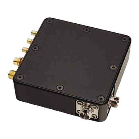
Newport 1607-AC User manual

Newport
Newport 2151 User manual

Newport
Newport 1807 User manual
Newport
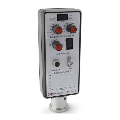
Newport 2107 User manual
Newport
Newport zW Series User manual

