Newport 1607-AC User manual

USER’S GUIDE
Balanced Photoreceivers
Models 1607-AC & 1617-AC
16x7 blncd rcvr RevC.fm Page 1 Friday, September 11, 1998 4:02 PM
These photoreceivers are sensitive to electrostatic
discharges and could be permanently damaged if
subjected even to small discharges. Ground your-
self adequately prior to handling these detectors
or making connections. A ground strap provides
the most effective grounding and minimizes the
likelihood of electrostatic damage
phone: (877) 835-9620
e-mail: tech@newport.com • www.newport.com

16x7 blncd rcvr RevC.fm Page 2 Friday, September 11, 1998 4:02 PM
Warranty
Newport Corporation guarantees its products to be free of defects for one
year from the date of shipment. This is in lieu of all other guarantees,
expressed or implied, and does not cover incidental or consequential loss.
Information in this document is subject to change without notice.
Copyright 2022, Newport Corporation. All rights reserved.
The New Focus logo and symbol are registered trademarks of Newport
Corporation
Document Number 90099911 Rev. A

Balanced Photoreceivers Contents • 3
Contents
Introduction 5
Overview . . . . . . . . . . . . . . . . . . . . . . . . . . . . . . . . . . . 5
Quick Start . . . . . . . . . . . . . . . . . . . . . . . . . . . . . . . . . 5
General Principles . . . . . . . . . . . . . . . . . . . . . . . . . . 7
Operation 11
Connecting the Power Supply . . . . . . . . . . . . . . . 11
Mounting the Photoreceiver . . . . . . . . . . . . . . . . . 12
Connecting the Optical Inputs . . . . . . . . . . . . . . . 12
Connecting the Electrical Output . . . . . . . . . . . . 13
Testing the Photoreceiver . . . . . . . . . . . . . . . . . . . 14
Customer Service 15
Technical Support . . . . . . . . . . . . . . . . . . . . . . . . . . 15
Service . . . . . . . . . . . . . . . . . . . . . . . . . . . . . . . . . . . . . 15
Specifications 16
16x7 blncd rcvr RevC.fm Page 3 Friday, September 11, 1998 4:02 PM

4 • Contents
16x7 blncd rcvr RevC.fm Page 4 Friday, September 11, 1998 4:02 PM
This page has been intentionally left blank

Balanced Photoreceivers Introduction • 5
Introduction
Overview
The Newport Model 16X7-AC balanced
photoreceiver consists of two matched photodiodes
and an RF amplifier that generates an output voltage
proportional to I1 - I2, the difference between the
photocurrents in the two photodiodes.
The Quick Start and General Principles sections
below give an overview of setting up the
photoreceiver and understanding its principles and
design. The chapters that follow give detailed
operating instructions and specifications.
Quick Start
The following parts are supplied with the
Model 16X7-AC balanced photoreceiver:
•Model 0923 Pico (m8) double-ended, male
power cable
•Model 0924 Pico (m8) male to banana plug
power cable
•Model 0927 SMB-to-BNC cable
The steps on the following pages describe the basics of
setting up and using the photoreceiver. The Operation
chapter contains more detailed information.
16x7 blncd rcvr RevC.fm Page 5 Friday, September 11, 1998 4:02 PM

6 • Introduction
1. Use one of the supplied power cables to connect
the photoreceiver to a ±15-volt power source that
can supply 200 mA. (Page 11.)
For the Newport Model 0901 power supply, use
the 0923 power cable. For other power supplies,
use the 0924 banana plug power cable.
When using the 0924 cable, take care to hook up
the banana plugs as follows to avoid damaging the
photoreceiver: Red = +15 V, Black = -15 V, Green =
Ground.
2. Mount the photoreceiver to your optical table. A
pair of 8-32 and a pair of M4-threaded holes are
located on the bottom of the unit. (Page 12.)
3. Connect the optical source to one or both optical
inputs. (Page 12.)
For the free space model, take care not to overfill
the photodiode. The 1607-AC has a 0.4-mm
diameter photodiode; the 1617-AC has a 0.1-mm
diameter photodiode.
To prevent saturation of the RF amplifier, keep the
input power below the saturation power shown on
page 16.
The optical power must remain below the absolute
maximum power listed in the specifications on page 16.
Exceeding the maximum power can damage the
photodiode and the amplifier.
4. Use the low-frequency I1and I2outputs to check
and adjust the optical inputs so that the output
powers are in the desired 0–10 V range. (Page 13.)
You can use the I2 - I1output to fine tune the
optical power balance between the two diodes.
5. Finally, connect the RF Out SMA connector to the
desired load or instrument via a 50-Wcoaxial
cable. (Page 13.)
Note:
Note:
16x7 blncd rcvr RevC.fm Page 6 Friday, September 11, 1998 4:02 PM

Balanced Photoreceivers Introduction • 7
General Principles
The Newport Model 16X7-AC balanced photoreceiver
consists of two matched photodiodes and an RF
amplifier that generates an output voltage
proportional to I1 - I2, the difference between the
photo-currents in the two photodiodes. A functional
block diagram of the balanced photoreceiver is shown
in Figure 1, and a mechanical drawing is given in
Figure 2.
Figure 1:
Functional
block diagram
of the Model
16X7-AC
Figure 2:
Mechanical
drawing of the
balanced
photoreceiver
(fiber-coupled
version)
Transmission lines connect the photodiode to the
amplifier and the amplifier to the output. The
transmission lines help to preserve speed and reduce
parasitic inductance and capacitance that can cause
ringing. DC power is delivered to the balanced
photoreceiver through a microconnector on the side
Current
Monitor
Current
Monitor
Current
Monitor
D1
D2
+V
-V
Amp
I1
I1 - I2
I2
I2 - I1
RF Out
RF Output
Power
Connection
±15 V
Low-
Frequency
Monitor
Outputs
2x 8-32 THD
FC Connectors
for Fiber-Optic
Input
0.75"
(19.0)
2.50"
(63.5)
2.50"
(63.5) 2x M4 THD
16x7 blncd rcvr RevC.fm Page 7 Friday, September 11, 1998 4:02 PM

8 • Introduction
of the unit, and the entire package is shielded to
eliminate noise pickup.
Low-frequency Monitor Outputs
In addition to the RF output, the balanced photo-
receiver has three low-frequency monitor outputs, I1,
I2and I2 - I1. These monitor outputs can be used to help
align light onto the photodiodes and to perform low-
frequency diagnostics. The monitor outputs have SMB
connectors, and an SMB-to-BNC cable is provided
with the photoreceiver.
All three monitor outputs have a transimpedance gain
of 10 V/mA. The bandwidth of the I2 - I1output is DC
to 15 kHz, and the bandwidth of the I1and I2outputs is
DC to 100 kHz.
Responsivity and Input Power
The Model 1607-AC uses a matched pair of silicon
photodiodes, and the Model 1617-AC uses a matched
pair of InGaAs photodiodes. Figure 3 shows the
typical responsivity of the photodiodes.
Figure 3:
Typical
responsivities
of the Silicon
and InGaAs PIN
photodiodes in
the 1607-AC
and 1617-AC
The amplifier has a maximum input current of 2 mA;
to avoid damage to the amplifier, never exceed this
input current. The Model 1607-AC has a peak respon-
sivity of 0.5 A/W, which means that 2 mA of photo-
Responsivity, A/W
1000 1200 1400 1600 1800
0.0
0.2
0.4
0.6
0.8
1.0
Wavelength, nm
800
600
400
1607-AC (Silicon)
1617-AC (InGaAs)
16x7 blncd rcvr RevC.fm Page 8 Friday, September 11, 1998 4:02 PM

Balanced Photoreceivers Introduction • 9
current corresponds to a maximum input optical
power of 4 mW. The Model 1617-AC has a 1.0-A/W
peak responsivity, and so the maximum input optical
power is 2 mW. At wavelengths away from the peak
responsivity the maximum input optical power scales
inversely with the responsivity.
Gain, Bandwidth and Noise
The RF amplifier is a low-noise device with 50-Winput
and output impedances. The RF amplifier’s trans-
impedance gain is 700 V/A, and the amplifier is AC-
coupled with a 40-kHz low-frequency roll-off.
The RF output stage can drive up to +12 dBm into a
50-Wload. To avoid saturating the RF amplifier, keep
the input optical power below about 2 mW for the
1607-AC and below 1 mW for the 1617-AC.
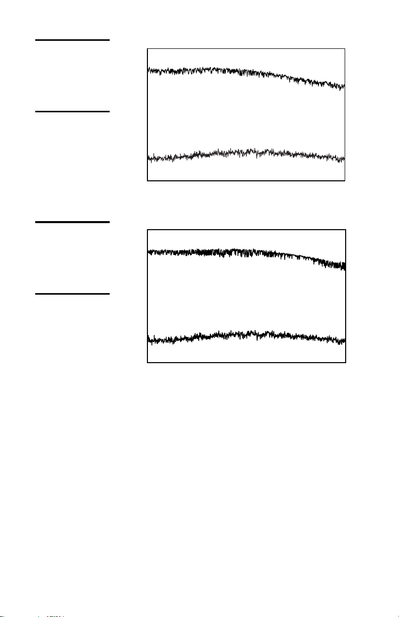
The RF bandwidth is 650 MHz for the Model 1607-AC
and 800 MHz for the Model 1617-AC. Figures 4 and 5
show typical frequency responses for the two photo-
receivers. From the bandwidths, we estimate rise times
of 0.8 ns for the 1607-AC and 0.6 ns for the 1617-AC.
Figures 4 and 5 also show the typical noise spectrum.
Since the RF amplifier is the dominant source of noise,
the noise spectrum is the same for both the 1607-AC
and 1617-AC. The noise is frequency dependent and
has a minimum input noise current in the 40-kHz to
100-MHz range of about 20 pA/ÖHz. This corresponds
to a minimum noise-equivalent power (NEP) of
40 pW/ÖHz for the 1607-AC and 20 pW/ÖHz for the
1617-AC.
16x7 blncd rcvr RevC.fm Page 9 Friday, September 11, 1998 4:02 PM
10 • Introduction
Figure 4:
1607-AC typical
frequency
response and
noise spectrum
Figure 5:
1617-AC typical
frequency
response and
noise spectrum
From 40 kHz to 800 MHz the integrated input noise
current is approximately 1.5 µArms. Multiplying this
by the 700-V/A transimpedance gain gives an output
voltage noise of 1.1 mVrms.
The 1.5-µArms integrated input noise current corres-
ponds to an equivalent input optical noise of 3 µW for
the Model 1607-AC and 1.5 µW for the Model 1617-
AC. This input optical noise level is the approximate
minimum optical signal that can be detected with
these photoreceivers. To detect a weaker signal, you
can reduce the noise by adding an electronic bandpass
filter at the output of the photoreceiver.
0 200 400 600 800 1000
Frequency, MHz
10 dB/div
Frequency Response
Noise
0 200 400 600 800 1000
Frequency, MHz
10 dB/div
Noise
Frequency Response
16x7 blncd rcvr RevC.fm Page 10 Friday, September 11, 1998 4:02 PM

Balanced Photoreceivers Operation • 11
Operation
Connecting the Power Supply
The balanced photoreceiver’s power supply connector
is a 3-pin shielded microconnector. This should be
connected to a ±15-V power supply capable of
providing a current of 200 mA. (We recommend the
Newport Model 0901 power supply.)
Two different power cables are shipped with the
photoreceiver: Model 0923 Pico (m8) double-ended,
male power cable for use with the Newport power
supply, and a Model 0924 Pico (m8) male to banana
plug power cable for use with other power supplies.
Using a Newport Power Supply
If you have a Newport Model 0901 power supply, use
the Model 0923 Pico (m8) double-ended, male power
cable to connect the photoreceiver to one of the power
supply’s 0.3-A microconnector outputs.
Be careful to align the notches on the connectors when
attaching the cable. If the connectors are not mated
correctly or the pins are bent, the photoreceiver may
be damaged.
Using Another Power Supply
Use the Model 0924 Pico (m8) male to banana plug
power cable when working with a power supply other
than the Newport Model 0901. Be sure to hook up the
banana plugs correctly, or the photoreceiver can be
damaged. The convention for the three banana plugs
16x7 blncd rcvr RevC.fm Page 11 Friday, September 11, 1998 4:02 PM

12 • Operation
is as follows:
Red = +15 V, Green = Ground, Black = -15 V.
Be careful to align the notches on the connectors when
attaching the microconnector end of the cable to the
photoreceiver. If the connector is not mated correctly
or the pins are bent, the photoreceiver may be
damaged.
Checking the Power Connection
With no light on the photodiodes, the photoreceiver
draws approximately 90 mA on the +15-V line and 10–
15 mA on the -15-V line.
If the current draw is 0 mA, the power supply cable
may have a bad connection. If the current draw is
greater than 150 mA, then the cable could be shorted
or there may be an internal problem with the photo-
receiver. Contact Newport for support and, if
necessary, instructions on returning the unit.
Mounting the Photoreceiver
The bottom of the photoreceiver has two pairs of holes
for mounting it to a post or pedestal. The pair labeled
“M” is for mounting with M4-threaded screws. The
other pair is threaded for 8-32-threaded screws.
Connecting the Optical Inputs
When connecting the optical inputs, keep the power
below the saturation power listed on page 16. This will
keep the RF amplifier operating in the linear region.
The optical power must remain below the absolute maximum
power listed in the specifications on page 16. Exceeding the
maximum power can damage the photodiode and the amplifier.
16x7 blncd rcvr RevC.fm Page 12 Friday, September 11, 1998 4:02 PM

Balanced Photoreceivers Operation • 13
The balanced photoreceiver is available with two types
of optical input. The -FS option is for free-space optical
coupling, and the -FC option has FC fiber connectors.
Using the Free Space (FS) Model
Direct an optical beam onto one or both of the
photodiodes.
Overfilling the photodiode can cause a decrease in the
photoreceiver’s frequency bandwidth. To avoid this,
you may need to focus the beam onto the photodiode.
The 1607-AC has a 0.4-mm diameter photodiode, and
the 1617-AC has a 0.1-mm diameter photodiode.
Using the FC Fiber-Coupled Model
For fiber-optic input, connect the fiber-optic cable
from your optical source to the FC connectors on the
sides of the photoreceiver.
Connecting the Electrical Output
Three low-frequency DC-coupled monitor outputs (I1,
I2, I2 - I1) are provided for diagnostics and for use when
first aligning an optical beam onto the photodiodes.
These monitor outputs have 10 V/mA gain. All three
outputs use SMB connectors, and an 0927 SMB-to-
BNC cable is provided with the photoreceiver.
1. Using the 0927 SMB-to-BNC cable, connect the I1
output to a voltmeter or oscilloscope.
2. Adjust the input optical power to achieve the
desired output voltage, somewhere in the
0–10-V range.
3. Connect the cable to the I2output and adjust the
input power to again achieve an output voltage in
the 0–10-V range.
4. (Optional) You can use the I2 - I1low-frequency
output tofine adjust the optical power balance
between the two photodiodes.
16x7 blncd rcvr RevC.fm Page 13 Friday, September 11, 1998 4:02 PM

14 • Operation
5. Connect the high-frequency RF Out SMA
connector to the desired load or instrument via a
50-W coaxial cable. This output has a 50-W
impedance and is AC-coupled with a 40-kHz
low-frequency roll-off.
Testing the Photoreceiver
To quickly test whether the photoreceiver is working,
you can perform a simple DC optical test.
1. Apply power to the photoreceiver.
2. Using a voltmeter or oscilloscope, measure the
output voltage from one of the low-frequency
monitor outputs.
With no light on the photodiodes, the output
voltage should be less than 10 mV. If the voltage is
greater than 10 mV, there may be a problem with
the power cable, or a photodiode or amplifier may
be damaged.
3. Shine light onto one of the photodiodes (room
light or a bright light source may be sufficient, or
you can use a CW laser source). Do not exceed the
saturation power shown on page 16.
4. Measure the voltage from the monitor output.
If you know the optical power and wavelength,
you can calculate the approximate output voltage
(Vout) using the expression Vout = Pin ×R×G, where
Pin is the input optical power (watts), Ris the
photodetector's responsivity in units A/W (see
Figure 3), and Gis the amplifier's transimpedance
gain (V/A). For the low-frequency monitor
outputs, the gain is 104V/A.
If you are testing with the high-frequency output, the gain
is 700 V/A.
Note:
Note:
16x7 blncd rcvr RevC.fm Page 14 Friday, September 11, 1998 4:02 PM

Balanced Photoreceivers Customer Service • 15
Customer Service
Technical Support
Service
16x7 blncd rcvr RevC.fm Page 15 Friday, September 11, 1998 4:02 PM
Information and advice about the operation of any Newport
product is available from our applications engineers. For quickest
response, ask for “Technical Support” and know the model
number and serial number for your product.
Hours: 8:00–5:00 PST, Monday through Friday (excluding
holidays).
Phone: 1-877-835-9620
Support is also available by email and chat
Chat: Connect with us at www.newport.com
Email: [email protected]
We typically respond to emails within one business day.
In the event that your device malfunctions or becomes damaged,
please contact Newport for a return merchant authorization (RMA)
number and instructions on shipping the unit back for evaluation
and repair.

16 • Specifications
Specifications
Model 1607-AC Model 1617-AC
Wavelength Range 320–1000 nm 900–1700 nm
3-dB Bandwidth 40 kHz–650 MHz 40 kHz–800 MHz
Rise Time (estimated) 0.8 ns 0.6 ns
Typical Max. Responsivity 0.5 A/W 1.0 A/W
Transimpedance Gain 700 V/A 700 V/A
Max. Conversion Gain 350 V/W 700 V/W
Output Impedance 50 W50 W
Minimum NEP 40 pW/ÖHz 20 pW/ÖHz
Saturation Power 2 mW 1 mW
Absolute Maximum Power 4 mW 2 mW
Common-Mode
Rejection Ratio (typical)
25 dB 25 dB
Max. Output Power +12 dBm (into 50 W) +12 dBm (into 50 W)
Photodiode Material/Type Silicon/PIN InGaAs/PIN
Photodiode Diameter 0.4 mm 0.1 mm
Power requirements ±15 V DC, £200 mA ±15 V DC, £200 mA
Optical input FC or Free Space (FS) FC or Free Space (FS)
RF Output Connector SMA SMA
Monitor Output Connector SMB SMB
I1and I2Monitor Bandwidth DC–100 kHz DC–100 kHz
I2-I1Monitor Bandwidth DC–15 kHz DC–15 kHz
16x7 blncd rcvr RevC.fm Page 16 Friday, September 11, 1998 4:02 PM
This manual suits for next models
1
Table of contents
Other Newport Receiver manuals

Newport
Newport 2151 User manual

Newport
Newport NIRVANA User manual

Newport
Newport 2107 User manual

Newport
Newport 2051 User manual

Newport
Newport 1601 User manual

Newport
Newport 1807 User manual

Newport
Newport 1801 User manual

Newport
Newport 2007 User manual

Newport
Newport zW Series User manual

Newport
Newport 1580-A User manual


