Newport Oriel PVIV Series User manual

IV STATION
User's Manual
Family of Brands – Corion®• New Focus™ • Oriel®Instruments • Richardson Gratings™ • Spectra-Physics®
MPVIV Rev: 04-20-11
PVIV SERIES

MPVIV
ORIEL®PVIV IV SYSTEMS
- 2 -
TABLE OF CONTENTS
I. INTRODUCTION .................................................................................................................................. 3
I.1 SPECIFICATIONS ................................................................................................................... 4
I.2 COMPUTER REQUIREMENTS .............................................................................................. 4
I.3 UNPACKING THE I-V STATION ............................................................................................. 5
I.4 UNPACKING AND SETTING UP THE SLIDE ASSEMBLY: ................................................... 7
I.5 INSTALLATION OF THE I-V TEST STATION 2 X 2” CHUCK ................................................ 8
I.6 INSTALLATION OF THE I-V TEST STATION 4 X 4” CHUCK ................................................ 9
I.7 INSTALLATION OF THE I-V TEST STATION 2 X 2” CHUCK WITH RAILS ........................ 10
I.8 INSTALLATION OF THE I-V TEST STATION 4 X 4” CHUCK WITH RAILS ........................ 11
I.9 INSTALLATION OF THE TEMPERATURE CONTROLLED VACUUM CHUCK .................. 12
I.10 WIRING THE I-V TEST STATION ......................................................................................... 13
I.11 INSTALLATION OF THE ORIEL®I-V TEST STATION SOFTWARE ...................................18
I.12 I-V TEST STATION SOFTWARE - INTRODUCTION ........................................................... 22
I.13 I-V TEST STATION SOFTWARE - USE ............................................................................... 29
II. SOLAR SIMULATOR MOUNTING DETAILS: ................................................................................... 31
II.1 MOUNTING FOR THE 2” X 2”............................................................................................... 31
II.2 MOUNTING FOR THE 4” X 4”............................................................................................... 32
II.3 NEWPORT TABLE MOUNTING PATTERN.......................................................................... 33
III. EC DECLARATION OF CONFORMITY............................................................................................. 36
IV. WARRANTY & SERVICE................................................................................................................... 37
V. CONTACT US .................................................................................................................................... 38
LIST OF FIGURES
Figure 1: Slide Assembly with stop blocks in locked down position ............................................................. 7
Figure 2: 2x2 solar simulator with the cell holder assembly in place............................................................ 8
Figure 3: 4x4 solar simulator with the cell holder assembly in place............................................................ 9
Figure 4: I-V Test Station 2 X 2” chuck with rails....................................................................................... 10
Figure 5: I-V Test Station 4 X 4” chuck with rails....................................................................................... 11
Figure 6: Temperature Controlled Vacuum Chuck system connections ................................................... 12
Figure 7: Diagram of the system electrical connections ............................................................................. 13
Figure 8: Banana Jack (SourceMeter) to BNC (thermistor) Cable connection........................................... 14
Figure 9: Rear view of a 4 x 4” solar simulator cable connection. .............................................................. 15
Figure 10: Rear view of a 4 x 4” solar simulator power supply. .................................................................. 15
Figure 11: Rear view of the wires connected to the SourceMeter.............................................................. 16
Figure 12: Rear view of the wires connected to the Reference Cell Meter ................................................ 16
Figure 13: Photovoltaic Cell with wires soldered on the bus bars. ............................................................. 17
Figure 14: Photovoltaic Cell installed onto a 2 x 2” Cell holding chuck ...................................................... 17
Please read these instructions completely before operating this equipment. The specification and operating
instructions apply only to the model(s) covered by this manual. If there are any questions or problems regarding the
use of this equipment, please contact Newport or the representative from whom this equipment was purchased.

MPVIV
ORIEL®PVIV IV SYSTEMS
- 3 -
I. INTRODUCTION
This Manual covers the setup and operation of all configurations of The Newport Oriel®I-V Station.
These products have been designed for operation with the Newport Oriel®Solar Simulator product line.
However, the components are modular and not restricted to Newport Oriel®products. Often adjusting cell
height with respect to another light source is all that is required.
The Solar simulator must be purchased separately.
The table below shows the various models and their components.
Newport
Oriel®I-V
Station
Model Num.
Source
Meter kit
3 Amp
Source
Meter kit
5 Amp
I-V
software
Reference
Cell
system
Single
cell holder
2”x2” cell
Single cell
holder
4”x4” cell
Dual cell
holder
with rails
2”x2” cell
Dual cell
holder
with rails
4”x4” cell
PVIV-201V
91545V
PVIV-202V
91567V
PVIV-210V
91150V
PVIV-211V
91150V 91545V
PVIV-212V
91150V
91567V
PVIV-401V
91556V
PVIV-402V
91578V
PVIV-410V
91150V
PVIV-411V
91150V 91556V
PVIV-412V
91150V
91578V
Note that there are now the following Models comprising a SourceMeter®, I-V software, associated
cabling, and 1 Ohm (4.5 Amp continuous) Resistor Box (90026597). The 3 Amp and 5 Amp Models
PVIV-200 and PVIV-400 have been superseded by PVIV-3A and PVIV-5A.
Newport
Oriel®I-V
Station
Model Num.
2400
SourceMeter
kit 1 Amp
2420
SourceMeter
kit 3 Amp
2440
SourceMeter
kit 5 Amp
PVIV-10A-I-AMP
Current Amplifier
10 Amp
I-V software
PVIV-1A
PVIV-3A
PVIV-5A
PVIV-10A
An accessory cable to adapt the Reference Cell cable Amphenol connector to two double Banana Jacks
is available to allow connection to a SourceMeter for I-V characterization. Part Number is 91150V-CBL.
A temperature controlled vacuum chuck system is available in place of the cell holder with rail. See
section I.9 for details.
A workstation, model 91590, is offered to help you mount and integrate these systems.

MPVIV
ORIEL®PVIV IV SYSTEMS
- 4 -
I.1 SPECIFICATIONS
Below is the Oriel®I-V Test Station specification table.
PVIV-1A PVIV-3A PVIV-5A PVIV-10A
Voltage range (V) ± 21 V ± 210 V ± 63 V ± 42 V ± 2.5 V
Current range (A) ± 1.05A ± 105mA ± 3.15 A ± 5.25 A -4 to +10 A
Output power (W) 22 W 66 W 55 W 25 W
Voltage resolution 10nV 10nV 10nV 10nV
Current resolution 10nA 10nA 10nA 100nA
Voltage Accuracy ± 0.03% ± 0.03% ± 0.03% ± 0.03%
Current Accuracy ± 0.06% @ 105mA
± 0.28% @ 1.05 A
± 0.12% @ 1.05 A
± 0.12% @ 3.15 A
± 0.12% @ 1.05 A
± 0.27% @ 5.25 A
± 0.07% @ 1.05 A
± 0.28% @ 10.0 A
All Models
Electric Interface 4-wire probing; 4 quadrant Sourcing and Sinking
Duration of I-V measurement (sec) 0.6 – 58 with 0.5 sec pre-sweep delay
Number of measurement points 2 – 1000
Thermistor temperature accuracy (°C) ± 0.25°C @ 25°C
Max. test device size (inch [cm]) 2 (5.08) for 2x2 fixtures 4 (10.16) for 4x4 fixtures
6.2 (15.6) for cooled chuck fixture
Software LabVIEW 2009 SP1 GUI
Measurements performed Voc, Isc, Jsc, Vmax, Imax, Pmax, Efficiency, Fill Factor,
R@Isc, R@Voc, Rshunt, Cell Temp (start), Cell Temp (end),
Exposure Duration, Date &Time Stamp
I.2 COMPUTER REQUIREMENTS
Minimum 2 GHz processor
Microsoft Windows XP™, Service Pack 2
512MB available RAM
CD-ROM
Minimum Hard drive space available 600 MB
Note: SourceMeter® is a registered trademark of Keithley Instruments, Inc.

MPVIV
ORIEL®PVIV IV SYSTEMS
- 5 -
I.3 UNPACKING THE I-V STATION
Each Newport Oriel®I-V Station comes with:
I-V Software package
- software installation CD
- this manual on the CD
Keithley SourceMeter®kit (1 Amp, 3 Amp and 5 Amp models)
- SourceMeter
- USB to GPIB controller
- red and black test leads (2 sets)
- cable, SourceMeter to shutter (9-pin DSUB to BNC)
- cable, SourceMeter to thermistor (Dual Banana Plugs to BNC)
- package of cell electrical strips
The following components are part of the various systems tabulated above:
Basic Chuck (single cell holder can be used for either test or Reference Cell, fixed position)
- for 2” x 2” cells
Cell holder assembly
Mounting plate assembly
Mounting couplers (2ea.)
Reference Cell holder
Mounting instructions
Misc screws
2x 8-32 x 1/4” socket head
6x 1/4-20 x 5/8” socket head
4x 6-32 x 5/16” socket head
M6 x 1 x 16 mm socket head
Misc hex wrenches
1x 7/64”
1x 9/64”
- OR -
- for 4” x 4” cells
Cell holder assembly
Mounting plate assembly
Mounting couplers (2ea.)
Reference Cell holder
mounting instructions
Misc screws
2x 8-32 x 1/4” socket head
6x 1/4-20 x 1/4” socket head
4x 6-32 x 5/16” socket head
M6 x 1 x 16 mm socket head
Misc hex wrenches
1x 7/64”
1x 9/64”
Dual cell chuck (separate holders for test and Reference Cells, cell holders are rail mounted)
- for 2” x 2” cells
Chuck assembly with rails
4x male female post

MPVIV
ORIEL®PVIV IV SYSTEMS
- 6 -
Mounting instructions
Misc screws
4x 1/4-20 x 3/8” socket head
4x 1/4-20 x 1/2” socket head
4x 6-32 x 1/2” socket head
Misc hex wrenches
1x 7/64”
1x 3/16”
- for 4” x 4” cells
Chuck assembly with rails
Right support
Left support
Mounting instructions
Misc screws
4x 1/4-20 x 3/8” socket head
4x 1/4-20 x 1/2” socket head
4x 1/4-20 x 3/4” socket head
4x 6-32 x 1/2” socket head
Misc hex wrenches
1x 7/64”
1x 3/16”
Reference cell system
-PV Reference Cell
- PV Reference Cell meter
- AC-DC power supply
- AC line cord
- Manual for Reference Cell system
Current Amplifier kit (10 Amp model PVIV-10A)
- 1 Amp SourceMeter
- 10 Amp Current Amplifier
- USB to GPIB controller
- software installation CD
- interlock plug
- red and black test leads (2 sets)
- cable, SourceMeter to shutter (9-pin DSUB to BNC)
- cable, SourceMeter to thermistor (Dual Banana Plugs to BNC)
- cable, Amplifier shutter out to Solar Simulator shutter in (2M BNC to BNC)
- cable, SourceMeter to Amplifier to fixture (Dual Banana Plugs both ends, 3 sets)
- connector, SourceMeter to cooled chuck fixture (Banana Jack to #8 Spade Lug)
- connector, SourceMeter to Probe kit (Banana Jack to Pin Jack)
- connector, SourceMeter to 2 Probe kit (Banana Jack to 2 Pin Jack)

MPVIV
ORIEL®PVIV IV SYSTEMS
- 7 -
I.4 UNPACKING AND SETTING UP THE SLIDE ASSEMBLY:
Your unit has been shipped with two of the stop blocks moved to their inner position and locked
down to prevent damage to the unit during shipping.
stop blocks (shown in shipped position)
Figure 1: Slide Assembly with stop blocks in locked down position
To set up your slide prior to its first use, loosen the two set screws on each of these inner stop blocks,
(indicated in the figure above) with the supplied 1/8 hex wrench, and slide the stop block outwards
until it is flush with the edge of the base plate (two other stop blocks are already in position on the
opposite rail). Tighten the two set screws on the front of each block, two set screws on the rear of the
block, and one set screw on top of the block. Your slide assembly is now ready for use.

MPVIV
ORIEL®PVIV IV SYSTEMS
- 8 -
I.5 INSTALLATION OF THE I-V TEST STATION 2 X 2” CHUCK
Reference figure 2
1. Install the solar simulator on a Newport 91590 workstation or on a standard optical table.
Please refer to the solar simulator manual for the installation and operating instructions for
the simulator.
2. Use the Mounting Couplers (2ea.) to connect the chuck base to the solar simulator base.
3. Use the slots in the chuck base to secure the chuck to the workstation.
The chuck is now aligned and will position either the 2x2 cell holder or a Reference Cell mounted in a
Reference Cell holder at the center of the beam and at the appropriate height.
Figure 2: 2x2 solar simulator with the cell holder assembly in place.

MPVIV
ORIEL®PVIV IV SYSTEMS
- 9 -
I.6 INSTALLATION OF THE I-V TEST STATION 4 X 4” CHUCK
Reference figure 3
1. Install the solar simulator on a Newport workstation or on a standard optical table. Please refer
to the solar simulator manual for the installation and operating instructions for the simulator.
2. Use the Mounting Couplers (2ea.) to connect the chuck base to the solar simulator base.
3. Use the slots in the chuck base to secure the chuck to the workstation.
The chuck is now aligned and will position either a test cell in the 4x4 cell holder or a Reference Cell
mounted in a Reference Cell holder at the center of the beam and at the appropriate height.
Figure 3: 4x4 solar simulator with the cell holder assembly in place.

MPVIV
ORIEL®PVIV IV SYSTEMS
- 10 -
I.7 INSTALLATION OF THE I-V TEST STATION 2 X 2” CHUCK WITH RAILS
Reference figure 4 and Section II.3
NOTE: this installation requires a Newport model 91590 workstation or a customer provided flat
surface mounting plate.
1. Install the 4 male/female mounting posts to the workstation/plate
2. Attach the chuck/rail assembly to the mounting posts.
3. Attach the 91150V Reference Cell (if used) to its mounting supports on the chuck/rail assembly.
4. Install the solar simulator on the workstation/plate. Please refer to the solar simulator manual
for a complete the installation and operating instructions for the simulator.
The chuck is now aligned with the 2x2 cell holder and the Reference Cell at the appropriate height. Slide
the chuck side to side to position either the test device or Reference Cell in the center of the beam.
Figure 4: I-V Test Station 2 X 2” chuck with rails

MPVIV
ORIEL®PVIV IV SYSTEMS
- 11 -
I.8 INSTALLATION OF THE I-V TEST STATION 4 X 4” CHUCK WITH RAILS
Reference figure 5 and Section II.3
NOTE: this installation requires a Newport model 91590 workstation or a customer provided flat
surface mounting plate.
1. Install the 2 mounting riser blocks to the workstation/plate, noting the “L” and “R” markings
on the riser blocks and in the drawing. Install so that the mating screw holes for the Solar
Simulator plate are inboard.
2. Attach the chuck/rail assembly to the workstation/plate.
3. Attach the 91150V Reference Cell (if used) to its mounting supports on the chuck/rail
assembly.
4. Install the solar simulator to its mounting riser blocks. Please refer to the solar simulator
manual for complete installation and operating instructions for the simulator.
The chuck is now aligned with the 4x4 cell holder and the Reference Cell at the appropriate height. Slide
the chuck side to side to position either the test device or Reference Cell in the center of the beam.
Figure 5: I-V Test Station 4 X 4” chuck with rails

MPVIV
ORIEL®PVIV IV SYSTEMS
- 12 -
I.9 INSTALLATION OF THE TEMPERATURE CONTROLLED VACUUM CHUCK
The Temperature Controlled Vacuum Chuck system can consist of the following parts. Depending
on your choice, your system may or may not include all the parts listed below:
PVIV-TC-VAC Temperature Controlled Vacuum Chuck Assembly
PVIV-PROBE-KIT PVIV Probe Kit (right angle bracket and magnetic base probe)
PVIV-PROBE-REPL PVIV Probe Tip Replacements (package of 5)
PVIV-CHILLER Chiller
PVIV-VAC-PUMP Vacuum Pump 110V
PVIV-VAC-PUMP-220 Vacuum Pump 220V
To mechanically install the Temperature Controlled Vacuum Chuck Assembly for a 2x2 system
refer to section I.7 (some extra hardware will remain)
To mechanically install the Temperature Controlled Vacuum Chuck Assembly for a 4x4 system
refer to section I.8 (some extra hardware will remain)
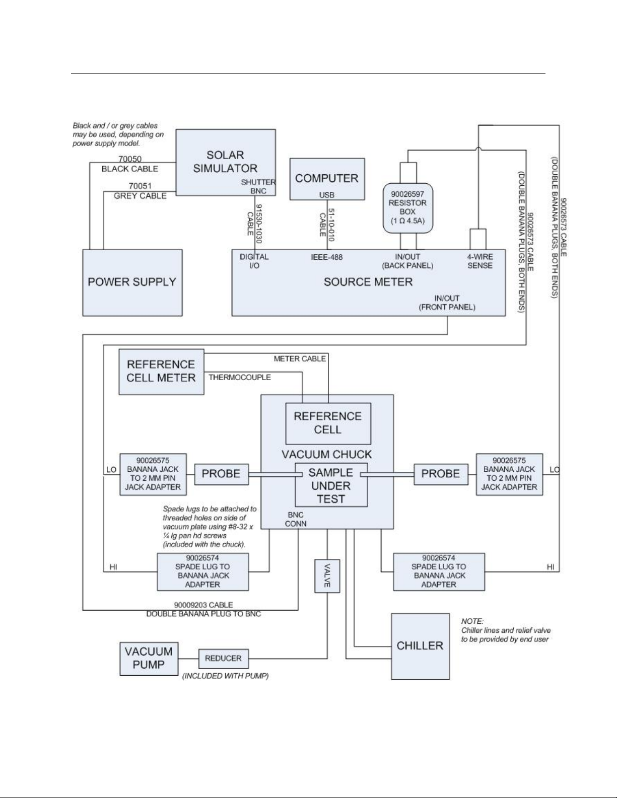
The following diagram is an illustration of connecting the Temperature Controlled Vacuum Chuck
system based on a typical setup with the following parts:
PVIV-TC-VAC Temperature Controlled Vacuum Chuck Assembly Qty 1
PVIV-PROBE-KIT PVIV Probe Kit Qty 2
PVIV-CHILLER Chiller (and heating capable) Qty 1
PVIV-VAC-PUMP VacuumPump Qty1
Figure 6: Temperature Controlled Vacuum Chuck system connections
MPVIV
ORIEL®PVIV IV SYSTEMS
- 13 -
I.10 WIRING THE I-V TEST STATION
Figure 7: Diagram of the system electrical connections
Certain optional components may not be available depending on the order configuration.
MPVIV
ORIEL®PVIV IV SYSTEMS
- 14 -
Notes on the electrical connections:
1. Be sure that the connectors on the power cables between the arc lamp power supply and the
solar simulator housing are seated well and the jacks’ screws are tight. Refer to figures 9 and
10, which show a Solar Simulator for the 4 x 4 system. The 2 x 2 system uses a single cable.
2. A set of flat wire strips is provided as part of the SourceMeter kit. We expect you will find
these wires useful for soldering to your test cells. Additional sets of 10 wires can be ordered
as model 91541. Reference figures 13 and 14.
3. A 4-wire connection is used between the cell under test and the SourceMeter. Make these
connections to the rear terminals of the SourceMeter. A source (Input/Output) wire pair, one
connected to the top of the cell and one to the bottom, and a similar pair of meter wires (4-
wire sense) are used. Typically the bottom of the cell is connected to the HI terminal of the
SourceMeter, and the cell top to the LO terminal. Reference figures 11 and 14.
4. The Cell temperature is sensed by the blue, spring-loaded thermistor built into the Cell
Holder. It is in close thermal contact with the bottom of the PV Cell. If the User has not
purchased an Oriel fixture, the thermistor function may be incorporated into the User supplied
apparatus. The thermistor is Vishay (BC Components) P/N 2381-640-55103, Digikey P/N
BC2299-ND. It has a NTC resistance (10KΩ@ 25°C, -4390ppm / °C, Vishay Curve 01) read
by the Keithley®every second in standby mode, which is converted by the software to a
temperature in degrees C.
5. The thermistor has a 2-wire connection to the SourceMeter front panel (input/output) jacks.
These are isolated non-polar connections, so they may be interchanged with no ill effect.
Use the BNC to Dual Banana plug cable (90009203) as shown in figure 8.
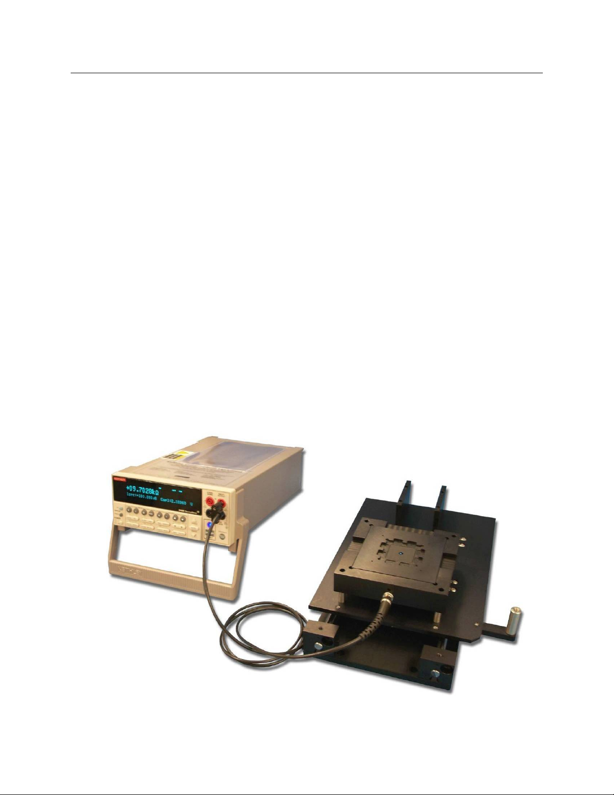
Refer to the photos below for the details of the electrical connections.
Figure 8: Banana Jack (SourceMeter) to BNC (thermistor) Cable connection

MPVIV
ORIEL®PVIV IV SYSTEMS
- 15 -
Shown on a rail-mounted 2 x 2” Dual Cell holding chuck (Reference Cell not shown)
Figure 9: Rear view of a 4 x 4” solar simulator cable connection.
Shutter
Connection
Solar Simulator
Power Supply
Connections
Figure 10: Rear view of a 4 x 4” solar simulator power supply.

MPVIV
ORIEL®PVIV IV SYSTEMS
- 16 -
Test leads
from test cell
(Red on top) Shutter Cable
from Solar
Simulator
GPIB
Connection PV Reference
Cell Meter
Figure 11: Rear view of the wires connected to the SourceMeter.
Figure 12: Rear view of the wires connected to the Reference Cell Meter

MPVIV
ORIEL®PVIV IV SYSTEMS
- 17 -
Red Wires
attach here
Sample Test Cell
Figure 13: Photovoltaic Cell with wires soldered on the bus bars.
Figure 14: Photovoltaic Cell installed onto a 2 x 2” Cell holding chuck

MPVIV
ORIEL®PVIV IV SYSTEMS
- 18 -
I.11 INSTALLATION OF THE ORIEL®I-V TEST STATION SOFTWARE
1. Before installing the Oriel®IV Test Station software, the GPIB communication must be set up and
run properly either by using the supplied USB/GPIB converter with its associated National
Instruments installation CD, or by using an existing installed GPIB card. National Instruments
drivers are required for the NI USB-GPIB hardware to communicate with the Keithley meter. The
required installer is included with the NI USB-GPIB hardware.
2. Insert the Oriel®I-V Test Station installation CD. Double click on ‘Setup’. Actual installation
procedure may be different than described below depending on the Operating System version of
the computer.
3. Click ‘Next’ if you want to install the software on the default directory. The installer will install the
program files to "C:\Program Files\Oriel Instruments" by default. Otherwise, click ‘Browse’ and
select the desired path. Then click ‘Next’. The window below will appear. Click ‘Next’.
4. Once the installation is complete, click ‘Finish’ in the window shown above.
5. The installer will create a shortcut "Oriel IV Test Station" in the Start Menu under "Programs\ Oriel
Instruments" by default. In order to create a shortcut on the desktop, right-click on “Oriel IV Test
Station”, then move the mouse to “Send To”, and then move the mouse to “Desktop (create
shortcut).”
6. The default locations for Recipes and Results are subfolders in C:\PVIV. This can be changed by
editing the “Oriel IV Test Station.ini” file which can be found in the application folder.
7. The application requires the LabVIEW 2009SP1 Runtime Engine from National Instruments. This
must be installed separately, and the installer (LVRTE901std.exe) is included on the installation
CD in the folder “LVRTE2009”. Double-Click “LVRTE901std.exe” to start the installation. The
window below will appear. Click ‘OK’.

MPVIV
ORIEL®PVIV IV SYSTEMS
- 19 -
8. The window below will appear. Click ‘Unzip’.
9. The window below will appear. Click ‘OK’.
10. The window below will appear. Click ‘Next’.
11. The window below will appear. Click ‘Next’.

MPVIV
ORIEL®PVIV IV SYSTEMS
- 20 -
12. The window below will appear. Click ‘Next’.
13. The window below will appear. Click ‘Next’.
14. The window below will appear. Click ‘Next’.
This manual suits for next models
14
Table of contents
Other Newport Test Equipment manuals


Popular Test Equipment manuals by other brands

Keithley
Keithley Interactive SourceMeter 2450 Declassification and security instructions

REED
REED R9030 instruction manual

Agilent Technologies
Agilent Technologies InfiniiVision 5000 Series user guide

Tektronix
Tektronix TDS 600B Performance Verification Manual

DRUCK & TEMPERATUR Leitenberger
DRUCK & TEMPERATUR Leitenberger LR-Cal TLDMM operating manual

Alcoscan
Alcoscan ACE III operating manual


