Newport PM 500 User manual

PM 500 Stage Tuning Manual

1 Setup
1.1 Materials Required
1. Small standard head adjustment screwdriver
2. PC interface through which to communicate with PM500, i.e. PCS
3. 10Mhz (minimum) oscilloscope with X-Y sweep mode
4. DMM (Digital Multi-Meter) with Voltmeter capability
1.2 Warm-up Controller
It is important to let the motion controller cards warm up for 15-30 minutes.
This will ensure that thermal fluctuations do not alter stage performance.
1.3 Oscilloscope Setup
1.3.1 Oscilloscope Calibration
Oscilloscopes from different manufacturers vary concerning labeling and
adjustments. The nomenclature used in this manual is applicable to all
oscilloscopes that are 30 MHz or higher, with X-Y sweep capability, and that
it can accommodate the procedures listed below.
—Note—
When performing the procedures discussed on the
following pages, power your oscilloscope from the
same outlet that powers the controllers. Take care that
the oscilloscope probe ground clips do not short any of
the components in the controller.
1. Plug into a stable, grounded (3-prong) 110 V power source, preferably
from the same source and ground that supplies the controller, such as the
power strip inside the tool.
2. Remove the ground clips from the oscilloscope probes. The ground clips
may be used if the oscilloscope has interference on the signal due to poor
grounding. The grounding clips must be used with caution to prevent them

from falling into the controller and damaging the system or shorting test
points to ground.
3. Allow a warm up period for the oscilloscope to stabilize (refer to your
oscilloscope manual).
4. Determine the probe gain (1X, 10X, etc.). Always verify that the probe
gain is taken into account when setting the oscilloscope (refer to your
oscilloscope manual).
Figure 1 Oscilloscope Calibration
5. Ensure that the probes are properly compensated by using the calibration
signal provided by the oscilloscope. This step should be accomplished
before beginning the tool calibration procedure. Adjust the probes for
sharp corners on the square wave. Verify that the calibration voltage is
displayed correctly when the variable amplitude adjustment is set in the
CAL position. Refer to your oscilloscope manual if you are not familiar
with this process.
6. Verify that the variable amplitude and frequency adjustments are set in the
CAL position.
Figure 2 Centered dot on screen
7. To setup the scope to be used in X-Y mode, set the mode to X-Y, coupling
to GND, and V/div to 1.0V/div (or .1V/div for 10X probe). Use the
horizontal and vertical position controls to center the spot on the center of
the screen. Re-verify, before adjusting each encoder, that the X-Y mode
ground reference position is at the center of the screen (some oscilloscopes
drift during warm-up and the centering may have been lost when other
scope settings were used). Failure to center the spot will cause errors in
the adjustment of the encoders.
Refer to the figures on the following pages for the location of the test points
and potentiometers The following procedures are to be used with Rev R and
later axis boards.
CAUTION
Only qualified personal should attempt to perform
stage tuning.
1.4 PCS Interface
During the tuning procedures it will be necessary to send commands to the
stages through PCS. The following are instructions on how to access the
interface through which commands are input and executed.
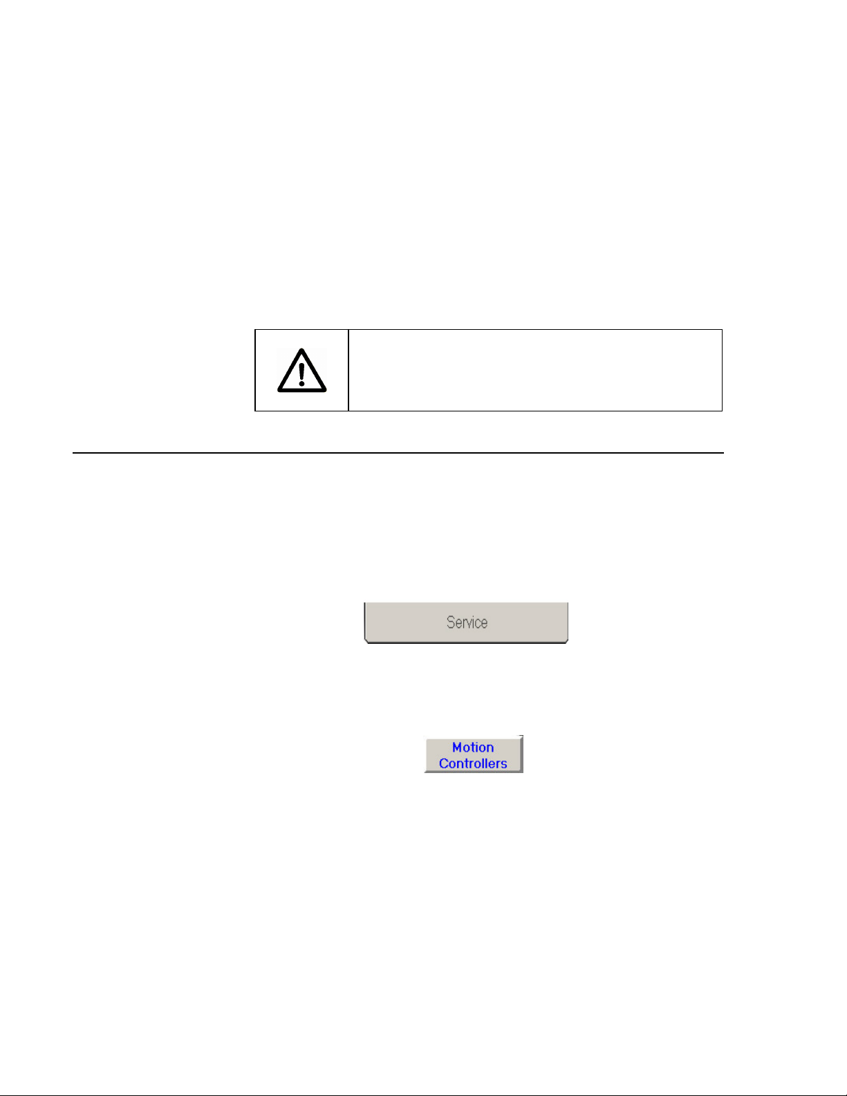
1. First, while in PCS, click on the Service tab at the bottom of the
screen to open the PCS Service window.
Figure 3 Service Tab Used to Open the Service Window
2. Once in the service window is open, click the button labeled
Motion Controllers.
Figure 4 Motion Controller Button in Service Window
3. Clicking the Motion Controllers button will open a new window
giving the user a choice of which motion controller he would like
access.
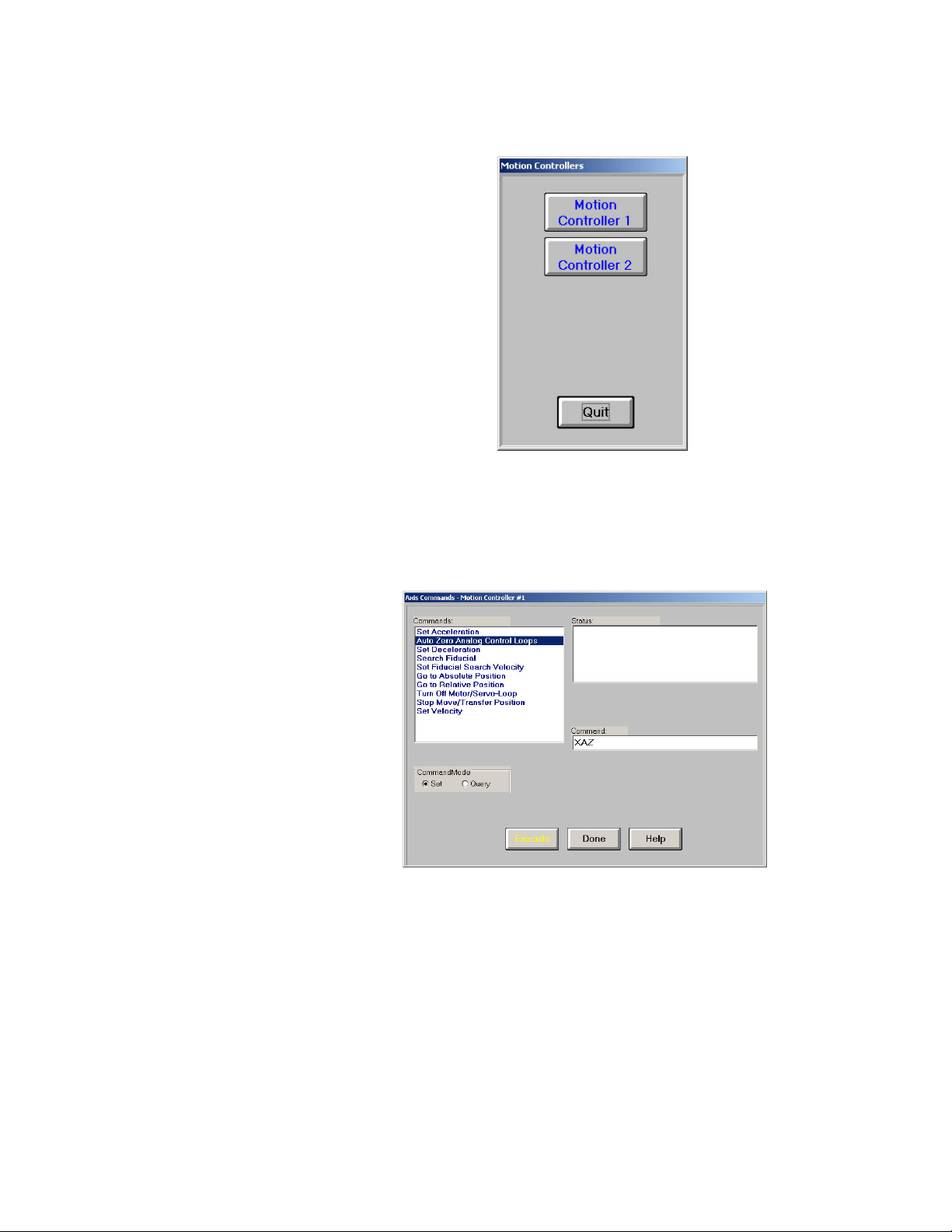
Figure 5 Motion Controller Selection Window
4. Clicking on one of these buttons will open up the interface window
of the selected stage.
Figure 6 Motion Controller Interface Window
5. From this window, commands can be entered in the field labeled
Command. Once a command is typed in, the yellow execute
button must be clicked to send the command to the stages. See
page back page for a list of commonly used commands.

1.5 Tuning Procedure Preliminaries
The following are procedures that should be reviewed before any tuning is
done. In some cases these preliminary procedures may eliminate any small
problems. During the tuning procedure the user will be asked to take
measurements using probes and make adjustments to trim potentiometers.
The test points and trim potentiometers lie on the individual axis boards
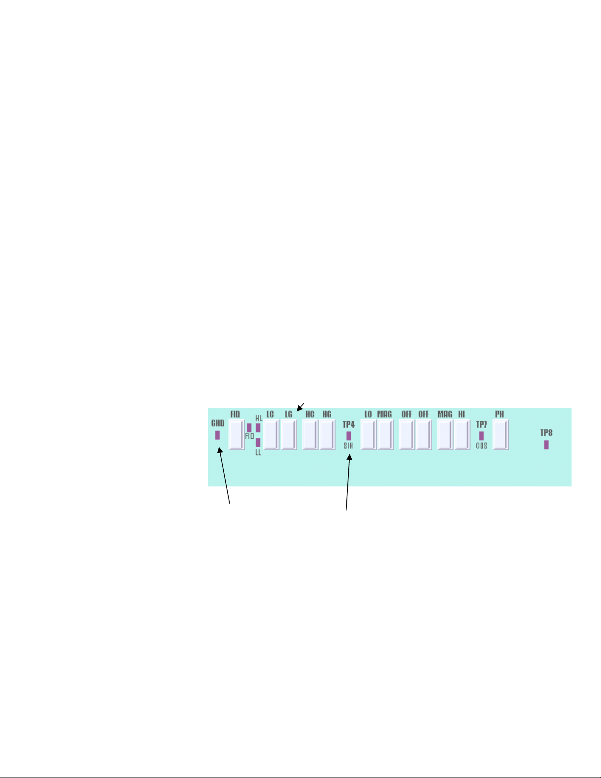
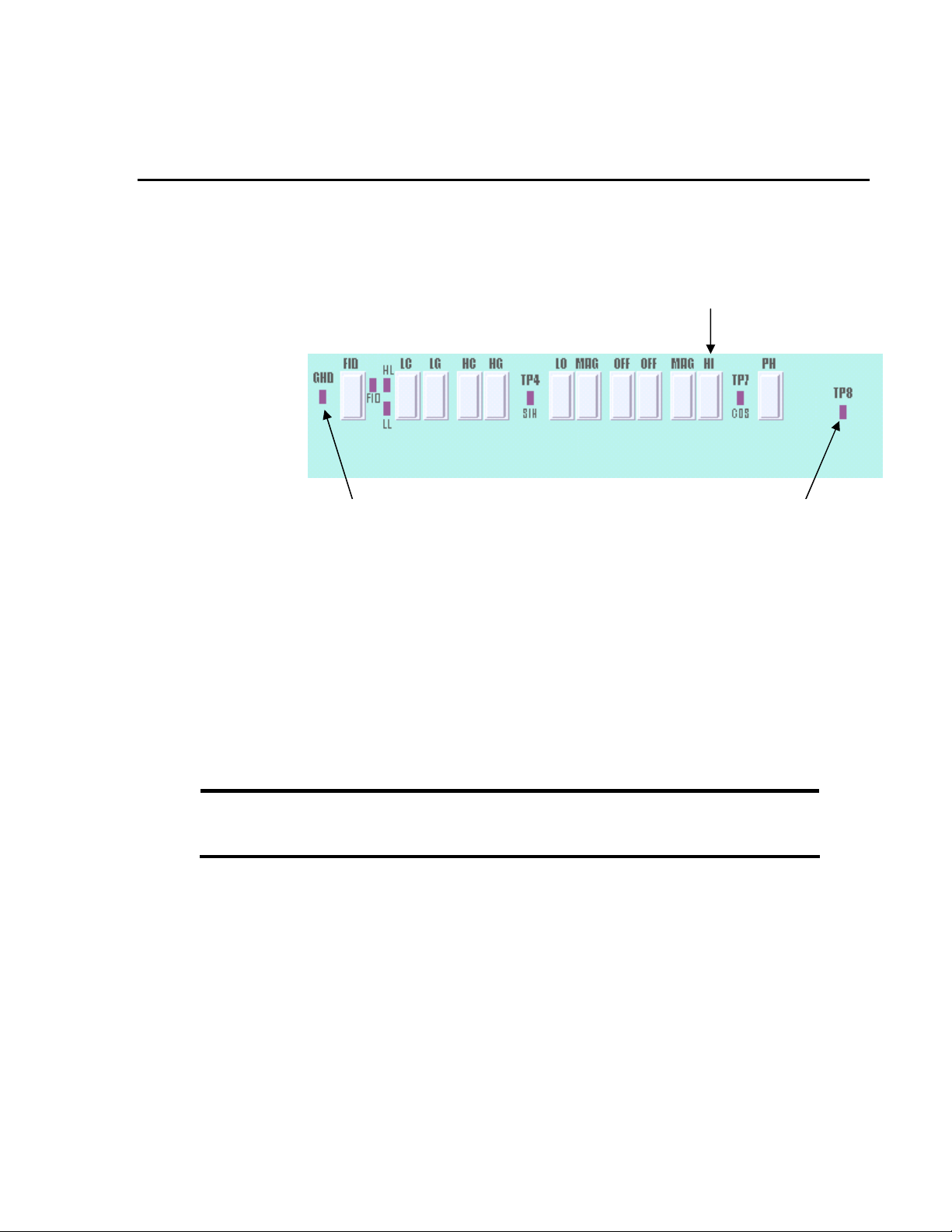
inside the motion controller. Throughout this document a picture of the top
part of the axis board looking from the component side where the trim
potentiometers are located will be referenced to show the user which test
point and trim potentiometer to use.
Figure 7 Top of Axis Board
The left side of the picture is the section of the axis board near the back of the
motion controller case. The right side is closer to the front of the motion
controller case.
NOTE
PM500 communication level “SCUM 1” is assumed throughout
this procedure. Input the commands indicated in this procedure
from the “Motion Controllers” button of the PCS “Service”
screen.
1. First issue a SCUM? query to the controller to ensure that correct
communications mode (SCUM1) has been setup. If the response is
“1” then SCUM1 is being used, if the response is “0” then issue a
SCUM1 command to setup the SCUM1 communications mode.
2. The next step before attempting to tune is to reset the PM 500
analog electronics to their original factory settings.
3. Input command SDEFEE and wait several seconds. The status box
should return with an “Operation Successful” response. This
command resets the PM500 analog servo electronic and motion
parameters to their default factory settings.

5. Input command SRSTART and wait several seconds. This command
resets the PM500 as would a hard reset. If this command is issued
through PCS the response through PCS will be that the “Operation
Failed”. This is normal and correct since the command reboots the
controller thus making it momentarily unavailable to GPIB queries.
NOTE
The SDEFEE and SRSTART commands should only be issued
once per controller at the beginning of the tuning processing and
not between tuning each axis board.
6. Auto-Zero the stage: Issue command <axis>AZ. Do not touch or
disturb the stage or tables during the Auto-Zero.
NOTE
Replace <axis> with the letter that corresponds to the axis
controller being tuned. For example: if tuning a 4L stage in the
Y-slot, enter YAZ as the command. The controller slots are
assigned as X Y Z A B C from left to right looking from the front
of the controller. Be sure to use the correct assigned alphabet to
avoid moving and damaging the wrong stage.
7. Wait 45 seconds until the Auto-Zero routine is complete. Then
confirm it is complete by entering the command: <axis>STAT?
and observe that the commands returns the <axis>D response. If
the stage is still busy <axis>B will be the response.
8. Once the Auto-Zero is complete, use the <axis>AZVAL?
Command to query how well the stage is finding its position.
9. Once the <axis>AZVAL? Command has been issued, PCS will
response with a number for each axis. The number will be in the form:
<axis>D$000004FF. The D signifies the Auto Zero was done, if the
Auto Zero is not finished there will be a B instead. In the number that
follows we are only interested in the last two pairs of numbers (or
letters). In this example 04 and FF are the pair in which we are
interested. These two pairs of digits tell us whether the stage is
performing properly. Another possible value would be D$0000FC03.
Below is a list of allowed values for the <axis>AZVAL? response, if
either of the last two pair of digits do not match the ones listed below,
tuning is necessary.

NOTE
Some axis cards do not have the HC and LC potentiometers. For
these stages there is no specification for the AZVAL?, other then
to get it as close to all zeros as possible. All other cards should
be within the specification listed below.
Figure 8 List of allowed values for <axis>AZVAL?
7. To save the new axis parameters to non-volatile memory: Issue the
command <axis>SAVEAX.
CAUTION
BEFORE ISSUEING ANY MOTION COMMANDS SUCH
AS SETUP0, SETUP10, ETC. ENSURE THAT THERE IS
NO TOOLING OR OBSTRUCTIONS THAT MAY CAUSE
A COLLISION WITH THE STAGE. Many of these motion
commands will cause the stage to travel its full length from
limit to limit. Actuators used with goniometers must be
tuned separate from the goniometer since the goniometer
as has a shorter travel length than the actuator. A
collision of the stage with any obstruction can cause
severe damage to the stage and/or tooling. Make sure
that traveling to the limits will not cause the stages crash
into any other stage or tooling. Also have your hand on
the E-stop when initially issuing the SETUP commands.
05
04
03
02
01
FD
FE
FF
00
FB
FC

NOTE
Most potentiometers are locked with lock-tight. It is necessary to
gently chip this off in order to make adjustments. Be sure to
relock the potentiometers when finished making adjustments.
Try not to apply lock-tight directly on top of the potentiometers.
A small amount on one side of the potentiometer should prevent
movement.

2 Stage Tuning
NOTE
To stop a stage after issuing a <axis>setup# command, execute
an <axis>M command. M stands for Motor Off.
2.1 Axis Encoder Adjustment
Oscilloscope Settings:
Sweep: X-Y mode (make sure to zero scope)
DC Coupling with 1V/Div
Test Points: TP4 (SIN), TP7 (COS) GND
Potentiometers Used: MAG, OFF, PH
Criteria: 4V +/- .5V
1Attach the Channel X probe to the TP4 (SIN) test terminal and the
Channel Y probe to TP7 (COS) test terminal. Make sure both
probes are grounded.
Sin Amplitude Sin Offset Cos Offset
Cos Amplitude
Ground Test Point
Sin Test Point Cos Test Point

2. Input <axis>setup0 command (remember this will move the stage
between physical limits of travel). If one cannot use <axis>setup0
then the stage can be moved by hand (using the hand actuator).
3. A Lissajous pattern should appear on the scope screen. If one does
not, it may be because the pattern is off the scale, in this case
adjust the scale until the pattern is visible.
4. Adjust the Lissajous pattern using the MAG (Magnitude), OFF
(Offset) and PH (Phase) potentiometers until the pattern has a
radius of 4 volts +/- .5V on both axes. Below are some example
Lissajous patterns.
1. Lissajous That Needs Phase Adjustment
2. Lissajous That Needs Offset Adjustment
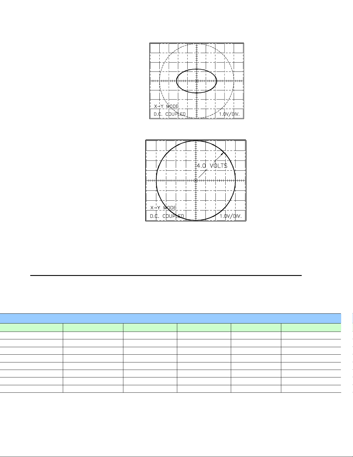
3. Lissajous That Needs Amplitude (MAG) Adjustment
4. Correct Lissajous Pattern
5. Once the Lissajous is correctly adjusted, issue the <axis>M command
to stop the stage motion.
2.2 Low Speed Loop Period
To perform the Low Speed Period Loop correctly, the user will need to
determine what kind of stage is being tuned as well as the ROM code of the
stage as this will determine the tuning parameters. The table below explains
list the possible stage types and their tuning parameters.
CHART
STAGE TYPE
SCALE
ROM CODE
RESOLUTION LO SPD HIGH SPEED
1V Mini Vertical
50 LPMM NMZD 0.1 40ms 800us
1V Mini Vertical
50 LPMM NMZC 0.05 40ms 800us
1A Actuator
50 LPMM NA 0.1 40ms 800us
1A Actuator
50 LPMM NAC 0.05 40ms 800us
2L - 8L 62.5 LPMM BMD 0.025 4ms 160us
2L - 8L 62.5 LPMM CMD 0.05 4ms 160us
33LR 62.5 LPMM CMI 0.05 4ms 160us
33LR 62.5 LPMM BMI 0.025 4ms 160us
1V Mini Vertical (AutoAlign): Y Axis stage
1A Actuator (AutoAlign): Actuator that moves Roll Axis (θZ)
1A Actuator (LaserWeld): Actuator that moves beam output housing
2L – 8L (AutoAlign): Stages that move X and Z Axes (generally 4L)
2L – 8L (LaserWeld): Stage that moves Upper Tooling (generally 4L)
33LR (LaserWeld): Stage that moves Lower Tooling (2 linear directions
and one rotational).
Once one has determined the type of card is being used follow the procedure
below to tune the Low Speed Loop Period.
Oscilloscope Settings:
Sweep: XT (time) mode 5 ms/Div
Vertical: DC Coupling with 1V/Div
Test Points: SIN (TP4), GND
Potentiometers Used: LG
Criteria: See Chart
1. Attach the Channel X probe to the TP4 (SIN) test terminal. Make
sure the probe is grounded.
2. Input <axis>Setup0 command
3. Adjust the LG potentiometer until the period of the sin wave on the
oscilloscope matches the criteria specified on the “LO SPD”
column of the chart.
4. Issue <axis>M command to stop stage.
LG Pot
Sin Test Point
Ground Test Point

2.3 Low Speed Loop Compensation Adjustment
Oscilloscope Settings:
Sweep: XT (time) mode 5 ms/Div
Vertical: AC Coupling with 1V/Div
Test Points:TP8, GND
Potentiometers Used: LC
Criteria: 2 Counter Clockwise turns past where
scope signal is flat
NOTE
Some newer cards do not have the LC and HC potentiometers
Adjustment of the Low and Hi Speed Loop is not necessary on
these cards.
1. Attach the Channel X probe to TP8. Make sure the probe is grounded.
2. Input the <axis>setup0 command
3. Turn the LC potentiometer clockwise until the stage begins to oscillate
and squeal. The oscillation will first be visible on the scope and the
squealing will become audible if one continues to turn the
potentiometer clockwise.
LC Pot
Ground Test Point TP8 Test Point
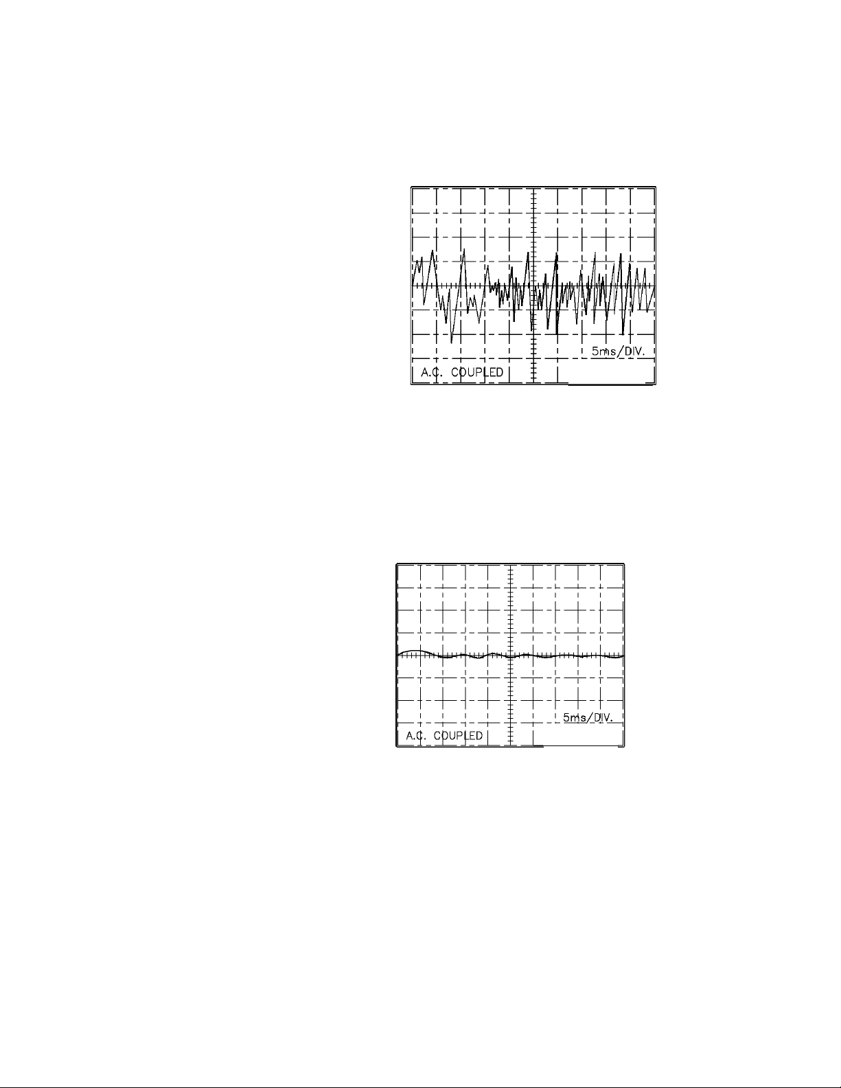
Figure 9 Scope Signal From Squealing Stage
4. Once the squealing has been observed and the oscillation has been
seen on the scope, turn the potentiometer counterclockwise just until
the signal on the oscilloscope becomes flat and steady and the
squealing stops. Then turn the potentiometer a 2 turns CCW past this
point.
Figure 10 Stage With No Squealing
5. Terminate stage movement with <axis>M command.

2.4 High Speed Loop Period Adjustment
Oscilloscope Settings:
Sweep: XT (time) mode 200 µ
µµ
µs/Div
Vertical: DC Coupling with 1V/Div
Test Points SIN (TP4), GND
Potentiometers Used: HG
Criteria: See Chart in section 2.2.
1. Attach channel X probe to Test Point 4 (SIN). Attach ground probe to
GND Test Point.
2. Input command <axis>SETUP1
—Note—
This command will put the stage in motion at a high
speed, try to make the adjustment as quick as possible
especially when tuning the bottom stages with heavy
load.
3. Adjust the HG trim potentiometer to achieve a sine wave with the correct
period according to the chart and the firmware code.
4. Terminate test by typing <axis>M.
HG POT
Test Point 4 (SIN)
Ground Test Point

2.5 High Speed Loop Compensation Adjustment
Oscilloscope Settings:
Sweep: XT (time) mode 5 ms/Div
Vertical: AC Coupling with 1V/Div
Test Points TP8, GND
Potentiometers Used: HC
Criteria: 2 Counter Clockwise turns past where
scope signal is flat
NOTE
Some newer cards do not have the LC and HC potentiometers.
Adjustment of the Low and Hi Speed Loop is not necessary on
these cards.
1. Attach channel X probe to Test Point 8 (TP8). Attach ground probe to
GND Test Point.
2. Input command <axis>SETUP2
3. Turn the HC potentiometer clockwise until the stage begins to oscillate
and squeal. Tuning the potentiometer further in the clockwise direction
will increase the amplitude of the scope signal and cause the squealing
to become louder.
HC POT
Ground Test Point Test Point 8
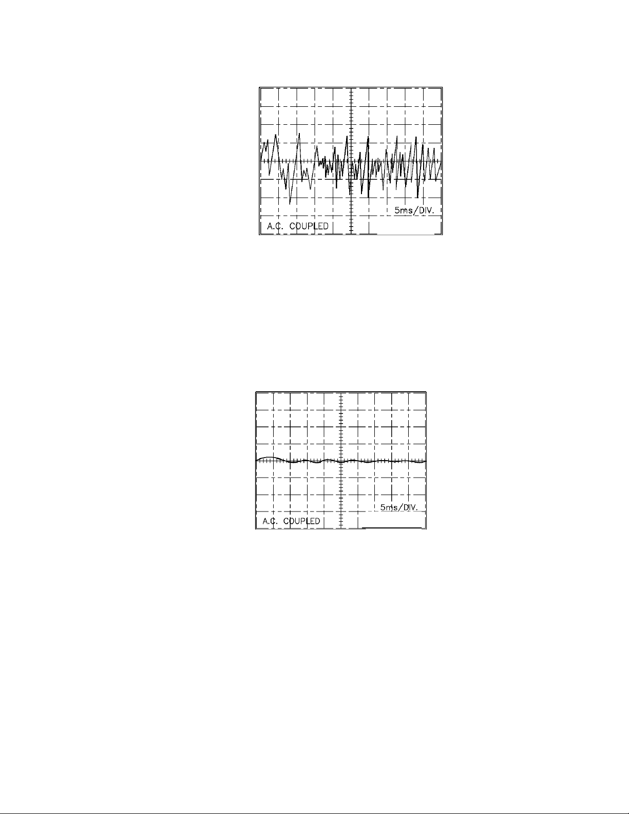
Figure 11 Stage Squealing on the Oscilloscope
4. Once the stage squealing as been observed turn the potentiometer counter
clockwise until there is no squealing and the signal looks flat on the scope.
Figure 12 Oscilloscope Signal with no Squealing
5. Once the squealing is gone and the signal looks flat, turn the potentiometer
a 2 turns in the counter clockwise direction.
6. Terminate the test with the <axis>M command.
2.6 DAC (HI) Offset Adjustment
Digital Multimeter Settings (DMM): DC Voltage
Starting measurement are typically below 5V
Test Points: TP8 and GND
Potentiometers Used: DAC (HI)
1. Disconnect oscilloscope probes from the axis card.
2. Attach DMM probes to Test Point 8 and Ground Test Point. Keep the
DMM probes away from the power supply.
3. Make sure the controller has been on for at least 20 minutes before
performing this test to ensure thermal stability during the test.
4. Input command <axis>SETUP3
—Note—
SETUP3 command does not move stages.
5. Adjust DAC (HI) potentiometer until a value of 0 +/- 20mV is achieved
on the DMM. The DAC (HI) potentiometer is very sensitive and there
may be some lag time between the turning of the potentiometer and
reading on the DMM so make adjustments slowly.
6. Terminate the test with <axis>M command.
DAC (HI) POT
Ground Test Point Test Point 8

2.7 Low Speed Offset Adjustment
Digital Multimeter Settings (DMM): DC Voltage
Starting measurement are typically below 5V
Test Points: TP8 and GND
Potentiometers Used: LO
1. To adjust the Low Speed Offset, connect DMM probes to the TP8 and
Ground Test Points.
2. Issue the <axis>SETUP4 command.
—Note—
SETUP4 command does not move stages.
3. Adjust the LO Potentiometer until the DMM reads 00.0 +/- 50mV.
4. Terminate test with <axis>M command.
5. Now go back up to section 2.6 and check to see if any further adjustment
is needed on the DAC(HI) Potentiometer. Adjust as needed until both
parameters are in spec.
LO POT
Ground Test Point Test Point 8
Other manuals for PM 500
1
Table of contents
Other Newport Test Equipment manuals


