NewTeam 1500-XT Mounting instructions

Installation Instructions
and User Guide
PLEASE KEEP THIS BOOKLET
FOR FUTURE REFERENCE
NEWTEAM 1500-XT
THERMOSTATIC POWER SHOWER
DEAR INSTALLER WHEN YOU HAVE READ THESE INSTRUCTIONS
PLEASE ENSURE YOU LEAVE THEM WITH THE USER
IN THE EVENT OF ANY QUERY PLEASE CONTACT
THE NEWTEAM CUSTOMER HELPLINE
Tel : 01536 264 012

Product Features
1NEWTEAM 1500-XT
NewTeam 1500-XT
• Integral pump
• Push-fit fittings
• 3 spray massage handset
• Thermostatic control
• BEAB approval of safety
255mm
240mm

Contents
2
NEWTEAM 1500-XT
Please read this booklet carefully and ensure a competent person undertakes the
installation.
Note: Following the headings in sequence will guide you through the installation
and operation of your NewTeam 1500-XT Power Shower.
PLANNING YOUR INSTALLATION
•Plumbing
•Electrics
FITTING YOUR SHOWER
• General
• The Unit
•Water/Electrical Connections
•Surface Mounting
•Recessed Fitting Pipework
•Riser Rail
USER INSTRUCTIONS
COMMISSIONING
Refer to back cover for Guarantee, Customer Service and Replacement Parts Policy.
In the event of any query regarding installation please contact the NewTeam Customer
Service Department
Tel: 01536 264 012 •Fax: 01536 409 201
In line with our policy of continual product development the specifications may be
varied and product design altered. We reserve the right to depart from the details
given in this manual without prior notice.
3
Pages
4 - 7
8
9
Installation and Operating Instructions
for NewTeam Power Shower
• 1500-XT
SPARE PARTS LISTING 10
INSTALLER NOTES 11-12
GUARANTEE 13

Planning your Installation
3NEWTEAM 1500-XT
Plumbing
Under no circumstances should the unit be connected directly to the mains
cold water supply, or to a combination boiler, or pressurised hot water system.
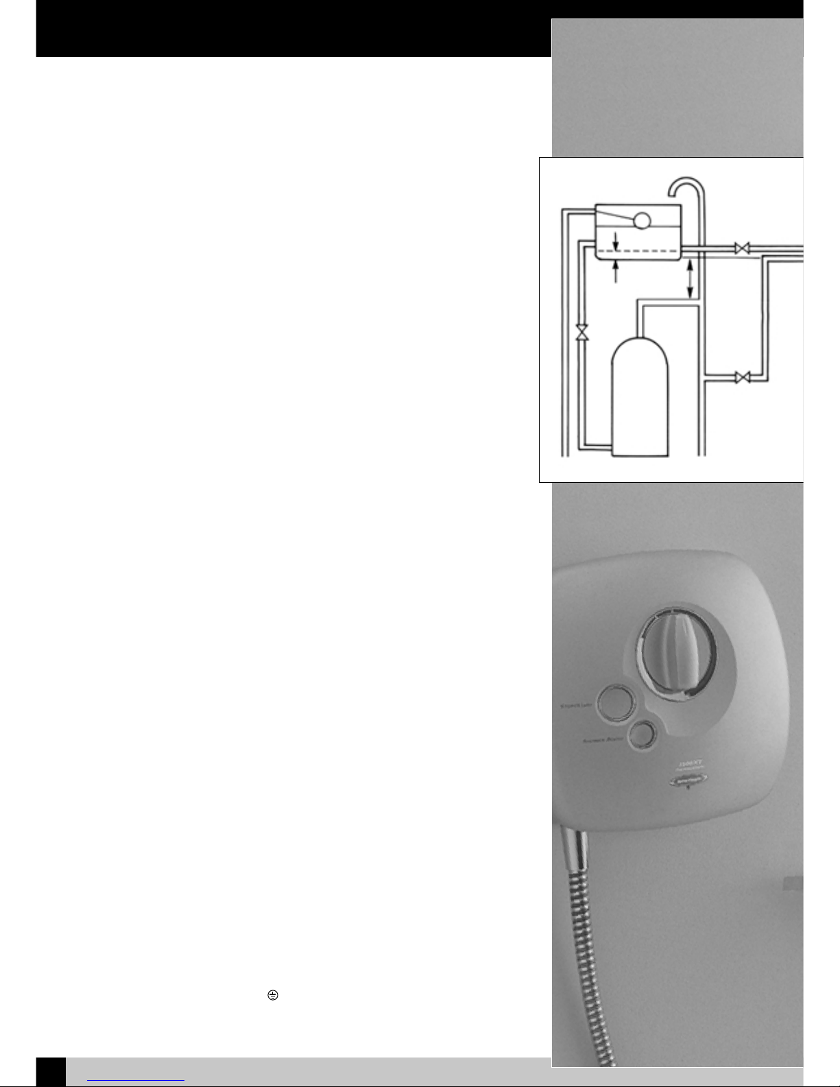
For correct operation of the NewTeam 1500-XT power shower, both hot and cold
water supplies must be gravity fed, at nominally equal pressures, from a cold water
storage tank, and a hot water storage cylinder.
We recommend a minimum of 115 litres (25 gallon actual) of cold water
supplied by a storage tank. Please ensure compliance with all Water
Regulations. Under no circumstances must the Power Shower be connected to the
mains cold water supply.
Please ensure maximum supply head of 10 metres, minimum 1 metre.
It is recommended that the hot water supply is at a temperature of 60ºC, in line with
British Standard 6700, British Water Regulations, and Plumbing Code of Practice.
Do not use jointing compounds when connecting, and do not solder within 300mm
of the unit.
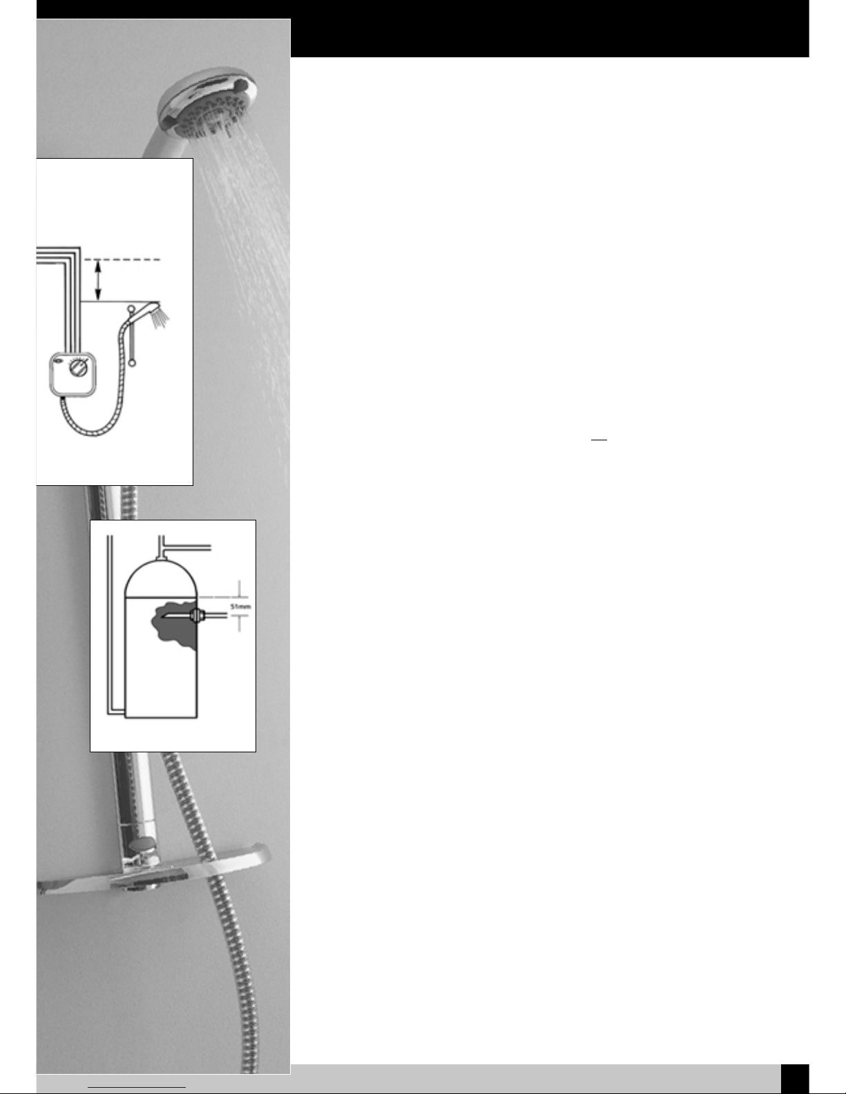
Before proceeding with the installation of this unit, check that your site requirements
allow the handset to be a minimum of 1 metre below the bottom of the cold water
storage tank to allow the 1500-XT to also operate on gravity.
WARNING: THIS APPLIANCE MUST BE EARTHED.
All electrical wiring for the shower must comply with the current
I.E.E Regulations which includes earth-cross bonding to all metal pipework.
IMPORTANT:
All plumbing should be completed before final electrical connections are made.
The shower must be connected to a 230/240 volt A.C electrical supply from a
13-amp ring main, via a fused double pole switch with at least 3mm contact
separation. The switch is to be clearly identifiable, a minimum distance of 2.5m from
a fixed tap or shower, i.e. mounted in an adjacent room or via a ceiling-type pull cord
switch. The unit should be fused at no more than 3 amps.
This appliance must be earthed, and all associated metal pipework earth
crossbonded in line with current I.E.E regulations.
As the colours of the wires in the cable (not supplied) used to connect to this
appliance may not correspond with the coloured markings identifying the terminals
in your switch, please follow the procedure below:
Please use the cable entry point provided. Failure to comply will eliminate any
BEAB approval.
Procedure:
•The wire, which is coloured Blue or Black, must be connected to the terminal that
is marked with the letter N.
•The wire, which is coloured Brown or Red, must be connected to the terminal that
is marked with the letter L.
•The wire which is coloured Yellow/Green must be connected to the terminal which
is marked with the earth symbol .
•The installation and wiring must comply with I.E.E regulations.
Electrics
Fig. 1 –Gravity Power Shower Installation
1m
Minimum
60mm

Fitting your Shower
4
NEWTEAM 1500-XT
In addition to the recommendation on `Planning your Installation’please take note of
the following:
•All plumbing should be completed before any electrical connections are undertaken.
•The unit can be connected to a combination cylinder system providing it
has a cold water storage capacity of 115 litres (25 gallons actual).
•When connecting pipework avoid using elbows: sweep or formed bends will
ensure optimum performance.
•Do not solder within 300mm of the unit.
•Do not run pump dry this will damage the internal seal and invalidate the warranty.
•All pipework to and from the unit should be a minimum of 15mm. Non-restrictive
isolating valves must be fitted on hot and cold supply pipes.
•Do not position unit in areas subjected to freezing conditions.
•The temperature of your stored water must not exceed 65ºC. A stored water
temperature of 60ºC is considered sufficient to meet all normal requirements
in line with the British Standard 6700.
WARNING –ALL CONNECTING PIPEWORK SHOULD BE EARTHED
Procedure - Plumbing Connections: Fig 1.
1. Isolate mains water and electrical supplies.
2. To empty the pipework open the hot and cold water taps.
3. Make your connection into the hot water supply pipe from the cylinder, ensuring
that it is the first draw-off (below the expansion pipe tee) to minimise the effects
of water draw offs elsewhere in the house, and a minimum of 1 metre from the
base of the cold storage tank and the expansion tee.
4. If this is not possible, a direct connection must be made from the hot water
cylinder with a cylinder flange, Fig 2.
5. The cold water supply should be taken directly from the cold storage tank,
and must be positioned 60mm below the cold feed connection to the hot
water cylinder. This should not be directly beneath the ball valve as aeration of the
water going to the shower could cause pump damage.
6. Run hot and cold pipework to the unit position.
We recommend that the unit is fitted at chest height, and set to one side of the
intended riser rail position, ensuring that the top of the unit is at least 75mm below
the base of the cold water tank.
IMPORTANT:
•The unit must be fitted on the finished tiled surface.
•Do not seal the edge of the unit to the tiled surface with any sealant, as the
gap below the back of the unit and the tiles is needed for ventilation.
•The outlet connection must be positioned at the bottom of the unit.
General
The Unit
Fig 2 - Cylinder Flange
1m
Minimum

Fitting your Shower
5NEWTEAM 1500-XT
Water/Electrical Connections
WARNING:
Do not fit fuse or switch on mains electrical supply until all plumbing work is
completed. Connecting pipework can feed from above or below the unit, or straight
through the wall at nominal centres of 40mm.
Top Feed = Hot on the right /cold on the left
Bottom Feed = Hot on the left/cold on the right
Back Feed = Hot on the bottom/cold on the top
Procedure:
•The integral fittings on the valve are of the self-seal push-fit type. All burrs and rough
edges must be removed from the end of the tube. Where chrome plated tube is
used, roughen or remove the first 25mm of plating
•The inlet elbows supplied are of a standard length, in some cases these will
need to be shortened for correct installation.
Fig 3 - Fixing points - 1500-XT
Collet
Fig 4 - Push fit fittings.
Cold
Hot
Removal of Front Cover
and Control Knobs
Please note that this product comes packaged with the front cover and control
knobs already in place. These have to be removed to install the shower. Please
follow the procedure below (Fig 5):
1. Pull off control knob (1).
2. To remove the graphic ring (2) which surrounds the main control knob, insert a
thin bladed screwdriver into the recess marked (3). gently prise off the ring,
revealing 2 fixing screws.
3. Remove lower logo (4) by inserting a thin bladed screwdriver in the slot, to
reveal the lower fixing screw.
4. Remove all 3 fixing screws (5). The cover can now be slowly removed - care
should be taken no to strain wiring which is attached to the front cover.
5. This procedure can be reversed to replace the front cover and control knobs
after installation to the wall.
1
2
5
5
5
3
3
3
4
Fig 5 - Removal of front cover.

Fitting your Shower
6
NEWTEAM 1500-XT
Surface Mounting
1) If exposed pipework is the option chosen, the pipes enter the unit on the right
hand side with the cold at the top. The pipe centres are 40 mm apart, and need
to penetrate the mixer valve connections by a minimum of 22mm.
2) Position the unit on the wall and mark the fixing hole positions. Drill the wall, insert
the wall plugs supplied, and secure the unit to the wall. Make the necessary
measurements, remove the unit from the wall, and bring the pipework and wiring
to finished positions.
3) Make the hot water connection into the hot water supply pipe from the cylinder,
ensuring that it is the first draw off (below the expansion tee), to minimise the
effects of water drawn off elsewhere in the house, and a minimum of 1 metre below
the base of the cold water storage tank. If connection to the hot water supply pipe
is not possible, a cylinder flange type connection may be used as illustrated (Fig.2
Cylinder connection flange)
4) Make the cold water connection into the base of the cold water storage tank,
60mm below the level of the cold water take off to the hot water cylinder.
5) Flush out the pipework
6) Detach the pipe entry grommet and, using a sharp knife or similar, remove the centre
(15mm dia.) portions, and refit the grommet.
7) Fit the shower unit over the pipework, and insert the mains wiring through the
aperture at the top of the base moulding. Ensure that the supply pipes are fully
inserted into the mixer valve “push fit”connections, and fix the unit to the wall.
8) Connect the wiring in line with the polarity indications moulded into the base unit.
Recessed Fitting Pipework
1) If the pipework is to be recessed, it should be let into the wall with the ends of the
hot and cold pipes standing 40mm off the finished surface of the wall, and centres
40mm apart, with the cold above the hot. Connections to the hot and cold water
supplies should be made as described above, knocking out inlet holes in rear of
unit.
2) Position the unit on the wall with the inlet pipes centred in the holes in the rear of
the base moulding, mark the fixing screw positions on the wall and remove the unit.
3) Drill the fixing screw holes and insert the wall plugs supplied.
4) Cut the plastic inlet elbows supplied to 40mm long from the centre of the elbow
as illustrated (Fig 6), and remove any burrs from the cut end. Fit the cut
inlet elbows into the push-fit connectors on the shower mixer valve.
5) Flush out the pipework.
6) Fit the shower unit over the pipework, and insert the mains wiring through the
aperture at the top of the base moulding. Ensure that the supply pipes are fully
inserted into the inlet elbow “push fit”connections, and fix the unit to the wall
using the fixing screws supplied.
7) Connect the wiring in line with the polarity indications moulded into the base unit.
40mm
Inlet
elbows
Fig 6 - 1500-XT

Fitting the Riser Rail
No Part Description
1Rail end cap
2Spirit level
3-4 Rail with slider attached
5Soap Dish
6Screw cap
7Soap dish fixing screw
Rail fixing screws &
wall plugs
Before proceeding with fitting the rail, identify each of the items supplied
using the illustration.
The slider need not be removed from the rail during fitting. The top of
the slider has a smooth profile, whereas the underside has a recess
revealing the grooves on the handset holder.
Fit the soap dish onto the bottom end of the rail and secure using the
small screw from the kit.
Position the rail on the wall, bearing in mind the heights of people likely
to use the shower, and the length of the hose when connected to the
shower and passed through the retaining hole in the soap dish. Mark
the wall to indicate the upper fixing screw position. Screw centres are
605 mm (approx. 23 - inches,) apart.
Drill the wall at the marked fixing position using a 6 mm drill, and loosely
fix the rail end, checking that the rail is hanging vertically using the spirit
level incorporated into the top end of the rail. The bubble should be
exactly between the two lines on the spirit level body. Mark the position for
the lower fixing screw, move the rail to one side, drill the wall, and fix
the lower end of the rail.
Check that the rail is vertical and tighten both fixing screws.
Slide the end cap into position on the top end of the rail, and fit the
screw cover into the recess in the soap dish.
When fitting the hose, it should pass through the larger hole of the soap
dish.
NOTE: The hose nut, and not the handset handle, fits into the slider,
and the slider moves more freely on the rail if gripped next to the rail,
rather than at the handset.
Spirit Rail Kit
Fig 7 - Riser Rail
7NEWTEAM 1500-XT

Commissioning
Fig 8 - NT 1500-XT Power Shower
The valve allows the maximum showering temperature to be set at a safe level,
preventing accidental scalding. This setting should be made during commissioning
and will require that the hot water cylinder is at its normal operating temperature.
IMPORTANT:
•The handset must be in the spray mode.
•We recommend the reading of User Instructions before proceeding further. This
will familiarise you with the operation of the shower.
Temperature Adjustment
Procedure:
Turn the brass mixer valve spindle fully clockwise, and then anti-clockwise until the
black line on the spindle is aligned with the groove on the mixer body, and fit the
control knob in the fully cold position. Check that it is correctly fitted by turning fully
clockwise to the stop, pull the knob off and check that the black line and groove are
aligned. Adjust if necessary. This sets the shower temperature to 38-40ºC, with the
control knob pointing to “12 o’clock”, if the hot water is at the recommended 60ºC.
Commissioning
1) Connect the shower hose –without the handset –to the outlet from the unit.
2) Turn on the hot and cold water isolating valves, and the electricity-isolating
switch, and place the open end of the shower hose in the shower tray or bath.
3) Set the temperature control knob to cold, fully clockwise, and press the
“Stop/Start”button.
4) Cold water will flow from the hose, and this should be allowed to continue for 2
minutes, after which time the control knob may be turned to the “12 o’clock”position.
Allow the water to run for a few minutes to stabilise the hot water flow, and then
check that the water is at a comfortable showering temperature.
5) If it is too hot or too cold, turn off the electricity-isolating switch, pull off the
control knob,and adjust the brass spindle anti-clockwise to increase the temperature
- clockwise to decrease. Replace the knob in the “12 o’clock”position, switch the
electricity on, and check the water temperature. Readjust as necessary until a
satisfactory temperature is achieved.
6) Pass the shower hose through the hole in the soap dish and, using the rubber sealing
washer supplied, fit the showerhead to the hose and place the showerhead in the
handset holder.
7) Press the Stop/Start button. Water flows from the shower head under the gravity
pressure from the storage tank. Press the Shower Boost button and the
pump starts, boosting the shower pressure.
Stop/Start Button
Temperature Control
Shower
Boost
Button
8
NEWTEAM 1500-XT

User Instructions
9NEWTEAM 1500-XT
1) To operate the shower, turn the control knob to the vertical - 12 o’clock position,
and press the Stop/Start button.
2) Adjust the shower temperature by turning the knob anti-clockwise - towards red,
for warmer temperature, and clockwise - blue, for cooler.
3) Setting the knob in the same position in future will give the same showering temperature.
4) If a more powerful shower is required, press the Shower Boost button.
NOTE: The Shower Boost facility is not available unless the Stop/Start button is
operated.
5) The handset holder has a friction grip on the rail and simply slides up and down
to adjust the height. The angle of the handset in the holder has 5, spring loaded
positions. To adjust, grip the handset handle next to the hose nut, and move it to
it’s required position.
6) The handset has 3 spray modes, which are selected by rotating the bezel around
the spray head.
7) Do not at anytime use bath cleaning liquids, powders or specified scratch
cleaners on any surface finishes. In order to avoid surface wear or chemical attack
on any of your shower fittings when cleaning, always use a damp cloth.
For persistent stains or marks, you may use a domestic liquid or soap.
NewTeam 1500-XT
Symptom Likely Cause Action / Remedy
Pump not operating Electric is not switched on Check all fuses and
electricity supply
Pump operates Micro switch is not Check micro switch
when mixer is operating correctly lever is securely located
switched off
No water flow Isolating valves turned off Turn on isolating valves
(Hot or Cold) Check cold water storage
tank has not run dry
Poor performance Poor hot or cold flow Check hot and cold supplies
Pump motor may have Allow unit to cool and
overheated it will automatically re-set
Check for adequate ventilation
Unit may be in the wrong Check that the top of the
position unit is at least 75mm below
the base of the cold
water storage tank
Troubleshooting
Fig 9 - NT 1500-XT Power Shower
Stop/Start Button
Temperature Control
Shower
Boost
Button

Spare Parts Listing
10
NEWTEAM 1500-XT
NewTeam 1500-XT
Item No. Part No. Description
1. SP-087-0105 * Base Assembly
2. SP-087-0507 * Front Cover
3. SP-087-0110 Pump Unit
4. SP-087-0097 Motor Cover
5. SP-087-0127 Pipe Connection
6. SP-490-0014 Front Cover Screws (not shown)
7. SP-087-0129 Latching Switch (not shown)
8. SP-086-0060 Long Inlet Elbow (x2) (not shown)
9. SP-087-0091 TPE Cover
10. SP-087-0154 Mixer Valve Complete
11. SP-087-0505 * Temperature Control Knob
12. SP-087-0503 * Start/Stop Button
13. SP-087-0504 * Shower Boost Button
14. SP-280-0100 * Spirit Rail & Slider Assembly (not Shown)
15. SP-280-0033 Soap dish/Rail End Shelf (not shown)
16. SP-280-0024 * Rail End Cap (not Shown)
17. SP-285-0820 * Hose (not Shown)
18. SP-168-0204 * Handset (not Shown)
19. SP-087-0230 Solenoid (not Shown)
* please state colour
5
10
1
9
4
3
Fig 10 - Front View
Fig 11 - Inside View
11
12
13
2

Installer Notes
11 NEWTEAM 1500-XT

Installer Notes
12
NEWTEAM 1500-XT

Guarantee/Service Policy
13 NEWTEAM 1500-XT
Part No. 404-0126 Issue 02/03
Guarantee
Thank you for purchasing a NewTeam product, which has been designed, manufactured and
tested, in the U.K., to the highest standards.
Guarantee. 2 Years, 1 Year - Parts and Labour Second Year- Parts Only
This is provided that:
1. The guarantee registration card is completed and returned within ten days complete with a copy
of proof of purchase.
2. The product is installed and operated in accordance with our instructions and has not been
misused or damaged.
This in no way affects your statutory rights as a consumer.
The information on the Guarantee card helps NewTeam to process any claims and contact you about
your product and its maintenance if required. The registration of your personal details is
purely for NewTeam use, and the other information helps us to make products for the future.
NewTeam Shower products are designed, manufactured and tested to the highest standards.
Should a complaint arise, products are guaranteed against faulty workmanship and materials for a
period of 12 months from the date of purchase, when in domestic use (second year guarantee is parts
only). For your guarantee to be valid, your shower pump must be installed by a competent
person, in accordance with the instruction manual.
NewTeam will repair or replace (at our option), free of charge, any faulty components during the guar-
antee period, provided it has been maintained and operated in accordance with our
instructions, and has not been misused or damaged.
Modification or repair of this product by person(s) not authorised by NewTeam will invalidate this
guarantee.
This guarantee applies to products purchased within the United Kingdom or Republic of
Ireland, but does not apply to products used commercially.
This guarantee does not affect your statutory rights.
Service Policy - Replacement Parts Policy
IMPORTANT:
In the event of product or component malfunction, DO NOT tamper with or remove the product
from site. Telephone NewTeam Customer Service Department on 01536 264 012 and be
prepared with the date of purchase, model number and a description of the complaint.
Our service staff are fully qualified to advise on correct installation procedures and will be able
to diagnose whether the fault will require a replacement part or a visit from a NewTeam
engineer.
If required, a service call will be booked, and either yourself or an appointed representative (who
should be a person of 18 years or over) must be present during the visit.
All site visits to product within the guarantee period will be carried out free of any parts or
labour charges provided the conditions of the guarantee have been adhered to. (Second year
guarantee is parts only)
All site visits to product out of guarantee will be subject to charges for parts and labour which
is payable by you or your appointed representative at the time of the visit. Charges will also be
levied on cancelled appointments, unless advised to NewTeam at least 24 hours in advance of
the agreed date and time.
We reserve the right not to undertake work where payment cannot be made to our engineer at
the time of the visit.
NewTeam hold stocks of components for all their range of products and these will be
maintained for the duration of their life.
Should a product be discontinued, spare parts stocks will be maintained, but in the event of a
part becoming unavailable NewTeam reserve the right to supply a substitute of equal quality.
The following payment methods can be used to obtain spare parts:
By post, pre-payment of proforma invoice by cheque or postal order.
By telephone quoting credit card (Mastercard, Visa or Visa Delta) details.
REPLACEMENT PARTS:
CUSTOMER SERVICE HOTLINE:

Guarantee
14
NEWTEAM 1500-XT
Please post immediately enclosing a copy of proof of purchase
GUARANTEECARD
NAME:
ADDRESS:
POSTCODE:
DATE OF PURCHASE:
PRODUCT PURCHASED FROM:
TOWN:
NewTeam’s philosophy is to offer outstanding products with quality and integrity,
please help us by taking the time to answer the following questions. Thank you.
POST BACK
FOLD AND TAPE AS INSTRUCTED OVERLEAF
MARKETING INFORMATION
1. Please state your profession: Plumber ❒Builder ❒Electrician ❒Customer ❒
Other ❒(please specify) ______________________________________________________________
2. Please state the reason for purchasing a shower: New Build ❒Replacement ❒
Renovation ❒Other ❒ (please specify) ________________________________________________
3. If the product is a replacement shower, please state the type and make of the shower it is
replacing: ____________________________________________________________________________
4. What influenced you to purchase the 1500-XT Power Shower? Advertisement ❒
Trade Press ❒Recommendation from Stockist ❒Recommendation from Installer ❒
Other ❒(please specify) ______________________________________________________________
5. Please state your main reason for purchasing the 1500-XT Power Shower:
NewTeam Product Knowledge ❒Product Features ❒Product Styling ❒Price ❒
Other ❒(please specify) ______________________________________________________________
Please tick here if you do not require any further information or product updates from NewTeam ❒
FOR NEWTEAM USE
This label identifies your product and
provides all the information needed
AFFIX PRODUCT LABEL HERE
✁
NewTeam Power Shower
1500-XT
Proof of purchase enclosed
YES ❐NO ❐

NewTeam Ltd.
Customer Service Dept.
Brunel Road
Earlstrees Industrial Estate
Corby
Northants
NN17 4JW
1st Fold
2nd Fold
3rd Fold
✁
Please tape down
Please tape down
Affix
Stamp
Table of contents
Other NewTeam Plumbing Product manuals
Popular Plumbing Product manuals by other brands

Cersanit
Cersanit SYSTEM 51 Instructions for assembly and use

Kohler
Kohler K-T15231 installation guide

American Standard
American Standard Repertoire Two-Piece Elongated Toilet... Specifications

Armera
Armera BW.223 installation instructions

Grohe
Grohe Chiara manual

Helvex
Helvex LV FUTURA1 installation guide

Galvin Specialised
Galvin Specialised CliniLever TCWMC80PC manual

Haws
Haws 1920 Installation, operation & maintenance instructions

Mira
Mira DISCOVERY Installation and user guide

Hans Grohe
Hans Grohe AXOR Starck Organic 12425001 Installation/User Instructions/Warranty

Moen
Moen ABERDEEN 165925 manual

Crosswater
Crosswater Berea 11-01 installation instructions