Nexans XPLORER 144 - 3X48 Operation and maintenance manual
NOTICE / INSTRUCTIONS
Tous les schémas, dessins, spécifications, plans et détails de poids, tailles et dimensions figurant dans la
documentation technique ou commerciale de Nexans ont un caractère purement indicatif et ne sauraient
engager Nexans ou être traités comme constitutifs d’une garantie de la part de Nexans.
All drawings, designs, specifications, plans and particulars of weights, size and dimensions contained in the
technical or commercial documentation of Nexans is indicative only and shall not be binding on Nexans or be
treated as constituting a representation on the part of Nexans.
Document : ABS1570/A
Date :
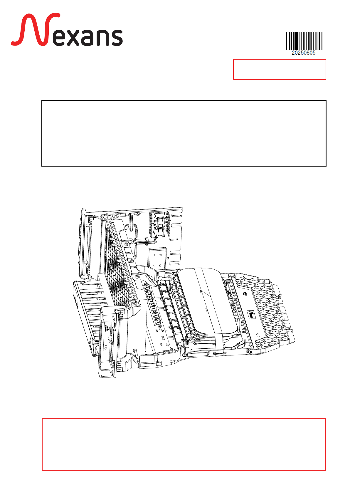
XPLORERTM 144 - 3X48
MODULE D’ÉPISSURAGE ET DE BRASSAGE
SPLICING AND PATCHING MODULE
25/08/2021

ABS1570/A
Table des matières
2/26
XPLORER 144 - 3X48
Table Of Contents
1. DESCRIPTION
OVERVIEW .......................................................................................................5
1.1. PRÉSENTATION DU PRODUIT
PRODUCT PRESENTATION ........................................................................................5
1.2. CARACTÉRISTIQUES TECHNIQUES
TECHNICAL CHARACTERISTICS .................................................................................6
1.3. KITS FOURNIS
PROVIDED KITS.........................................................................................................7
2. FIXATION DU MODULE
FIXATION OF THE MODULE.............................................................................8
2.1. CONDITIONNEMENT
PACKAGING............................................................................................................. 8
2.2. MISE EN PLACE DU DORMANT
INSTALLING THE FIXED CHASSIS ...............................................................................9
2.3. MISE EN PLACE DE LA PLAQUE DE VERROUILLAGE
INSTALLING THE LOCKING PLATE...........................................................................10
2.4. MISE EN PLACE DU BATTANT
INSTALLING THE SWIVELING PART .......................................................................... 11
3. RACCORDEMENT DU MEB 144
CONNECTION OF THE MEB 144.....................................................................12
3.1. ACCÈS À L’ORGANISEUR
ACCESS TO THE ORGANISER..................................................................................12
3.2. CHEMINEMENT DES LOOSETUBES ET DE LEURS FIBRES
ROUTING LOOSETUBES AND FIBRES ......................................................................13
4. FERMETURE DU MODULE
CLOSING THE SWIVELING CHASSIS ..............................................................16
5. POSE D’UN CORDON
INSTALLING PATCHCORD ..............................................................................17
6. ÉLÉMENTS PARTICULIERS DE MAINTENANCE
SPECIAL PROCEDURES FOR MAINTENANCE ..................................................18
6.1. REMPLACEMENT D’UN RACCORD
ADAPTER REPLACEMENT.........................................................................................18
6.2. PRINCIPE DE DÉPOSE DU MODULE
MODULE REPLACEMENT......................................................................................... 19
7. ANNEXES
ANNEX...........................................................................................................20
7.1. AUTRES KITS
OTHERS KITS ..........................................................................................................20

ABS1570/A 3/26
XPLORER 144 - 3X48
7.2. FIXATION AVEC ÉCROUS CAGES SUR MONTANTS 19’’
CAGE NUTS FIXATION ON 19’’ FRAMES .................................................................21
7.3. FIXATION DU KIT DE GUIDAGE
ROUTING KIT FIXATION.......................................................................................... 22
8. MAINTENANCE
MAINTENANCE ..............................................................................................24
8.1. REMPLACEMENT D’UN PIGTAIL
PIGTAIL REPLACEMENT ...........................................................................................24
8.2. REMPLACEMENT D’UN RACCORD
ADAPTER REPLACEMENT......................................................................................... 25
9. INSTRUCTION DE FIN DE VIE
END LIFE INSTRUCTION.................................................................................26
10. TRAÇABILITÉ
TRACEABILITY.................................................................................................26
10

ABS1570/A 4/26
XPLORER 144 - 3X48
PRÉAMBULE
PRELIMINARY WORD
Cette notice présente deux types de
produits :
- MEB axe à gauche pour fibre
conditionnée en loose tubes, faisant
l’objet de la présente notice.
- MEB axe à droite dont la symétrie
permet de reproduire la même
procédure de mise en œuvre que celle
du MEB axe à gauche.
This manual presents two types of
products:
- Left axis version for fibre conditioned
in loose tubes is represented in this
manual.
- Right axis version in which the symmetry
allows to repeat the same procedure as
the left axis one.
ABS1570/A 5/26
XPLORER 144 - 3X48
1. DESCRIPTION
OVERVIEW
1.1. Présentation du produit
Product presentation
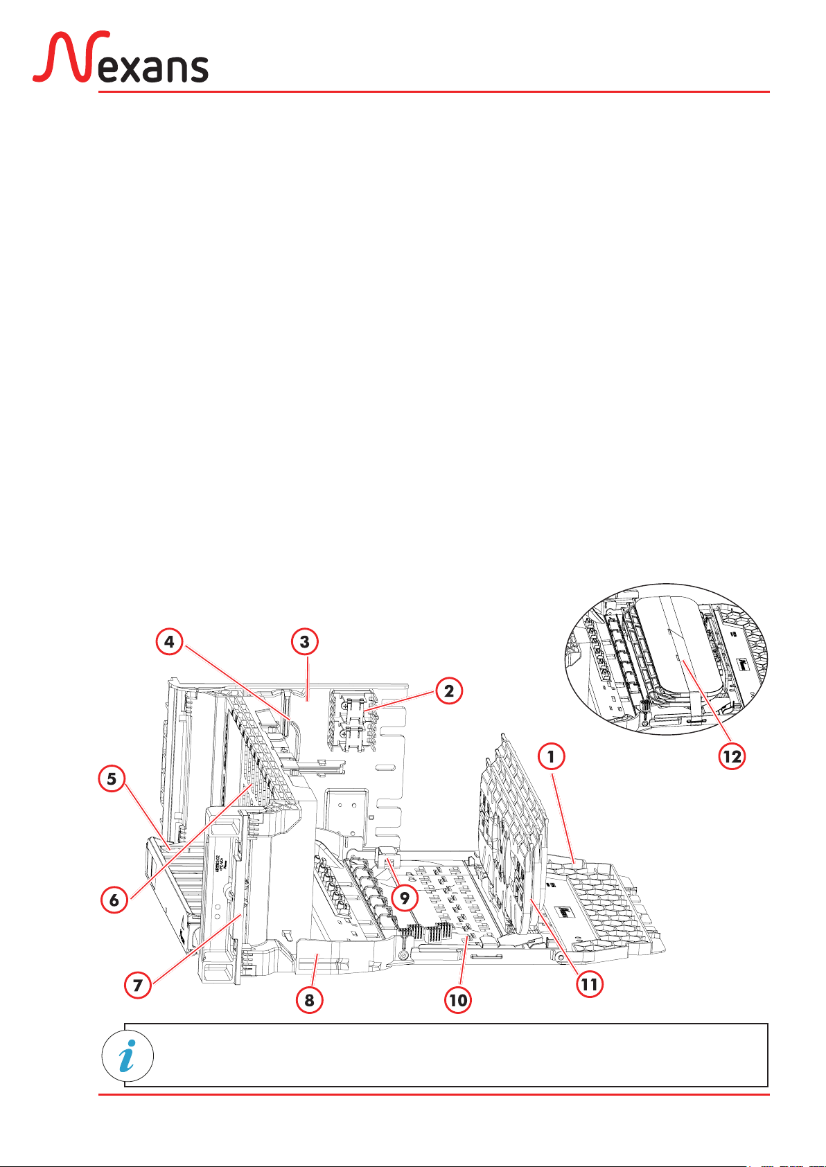
Les schémas représentent un module
axe à gauche.
The drawings represent a left axis
module.
1- Protective cover.
2- Tubes fixation comb.
3- Fixing bracket (fixed chassis).
4- Secondary coiling area for microbundles.
5- Support for patchcords management.
6- Front patch panel for 144 SC/APC
adaptors.
7- Locking plate.
8- Ensemble optique pivotant (battant)
9- Loose tube guide ring.
10- Rotating back plate for routing pigtails
(4 combs)
11- Organiser 3 cassettes of 48 optical fibres
12- Velcro strip.
1- Capot de protection.
2- Peigne de fixation des tubes.
3- Équerre de fixation (dormant).
4- Zone de lovage secondaire pour
micromodules.
5- Goulotte pour la gestion des cordons.
6- Panneau frontal de brassage pour 144
raccords SC/APC.
7- Plaque de verrouillage.
8- Ensemble optique pivotant (battant).
9- Anneau de guidage loose tube.
10- Platine de guidage des pigtails (4
peignes).
11- Organiseur 3 cassettes de 48 fibres
optiques.
12- Velcro de maintien.

ABS1570/A 6/26
XPLORER 144 - 3X48
1.2. Caractéristiques techniques
Technical characteristics
–Weight: 4.5 kg
–Height: 4U - 177.8mm
–Width: 19”/ETSI standard
–Depth: 185mm
– Poids : 4,5 kg
– Hauteur : 4U - 177,8mm
– Largeur : Standard 19”/ETSI
– Profondeur : 185mm
4U
19’’
ETSI
230mm
185mm
38mm
ABS1570/A 7/26
XPLORER 144 - 3X48
Description Qté /
Qty
Kit de fixation 19’’ standard
(£↕9,5mm) :
– Douilles
– Pions
– Plaque de verrouillage 19’’ 4U
Standard 19’’ fixation kit
(£↕9.5mm):
–Sockets
–Pawns
–Locking plate 19’’ 4U
5
5
1
1.3. Kits fournis
Provided kits
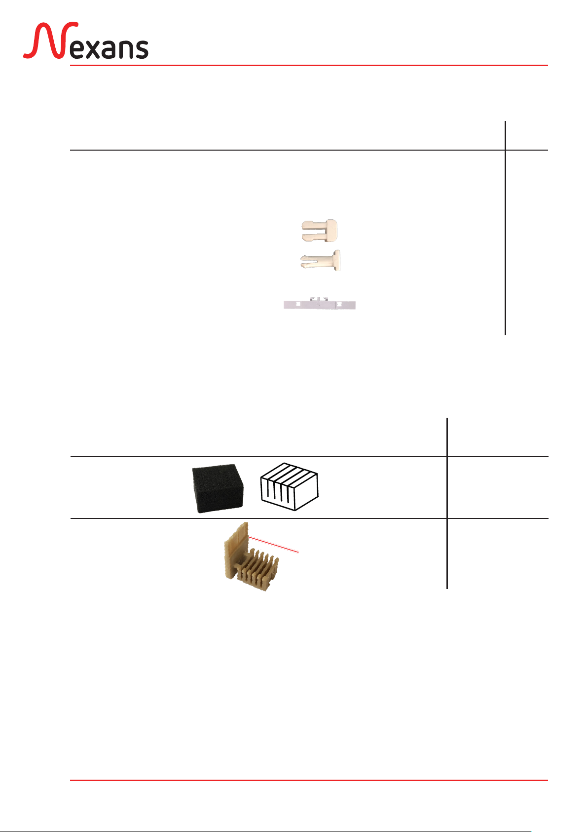
Listedespeignesfournis etdiamètred’utilisation Combs list and fitting diameter
Numéro du peigne
Comb number
Ø des tubes ou pigtails
Ø of tubes or pigtails
Qté
Qty
Peigne en mousse
Foam comb Ø 250μm à Ø 1,3mm 2
Already installed
Peigne plastique
Plastic comb Ø 900μm 4
Already installed
Outil
Tool
a
b
c
ABS1570/A 8/26
XPLORER 144 - 3X48
2. FIXATION DU MODULE
FIXATION OF THE MODULE
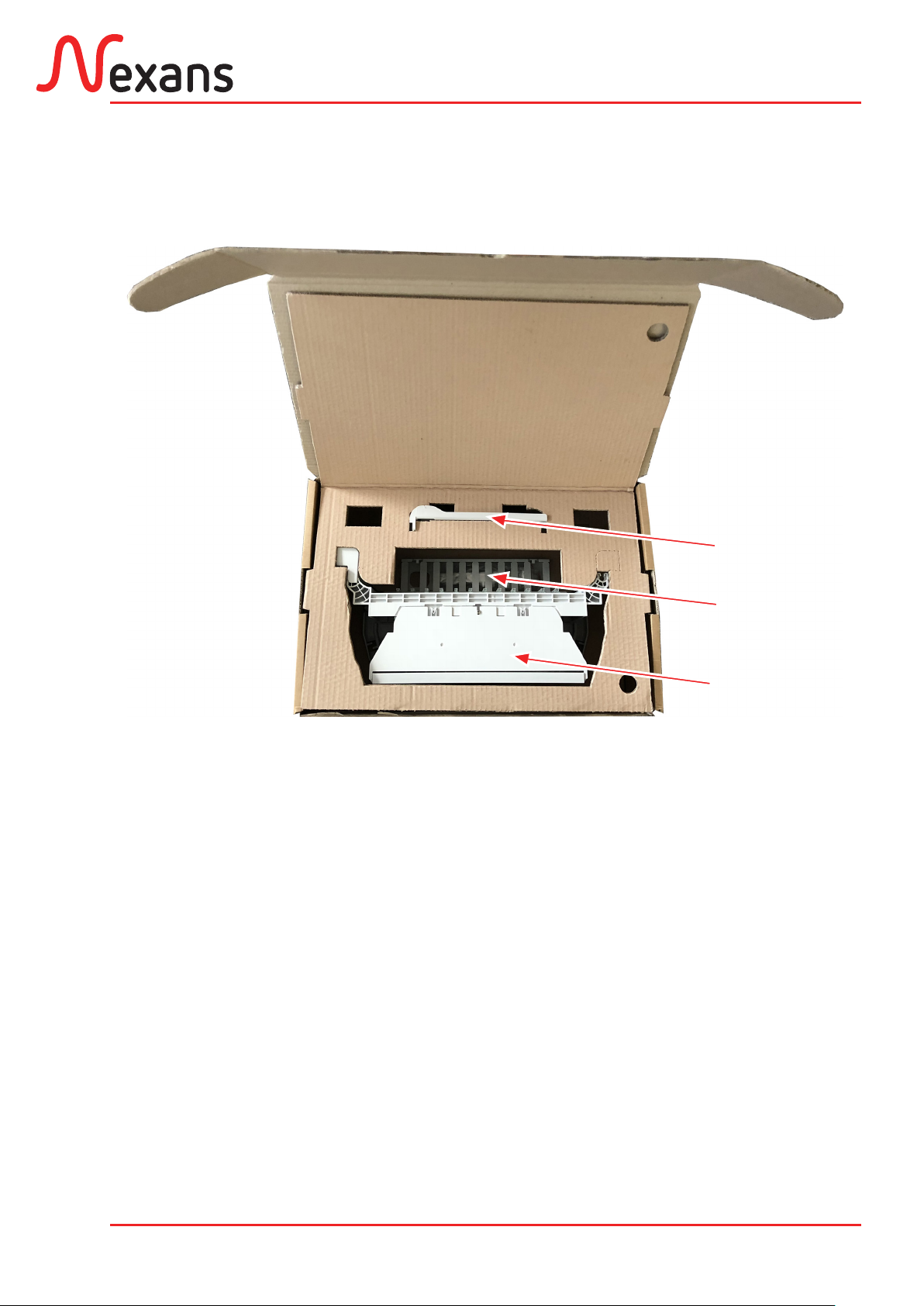
Dormant
Fixed chassis
Battant
Swiveling chassis
Accessoires
Accessories
2.1. Conditionnement
Packaging

ABS1570/A 9/26
XPLORER 144 - 3X48
19’’
9.5mm
Oui/Yes
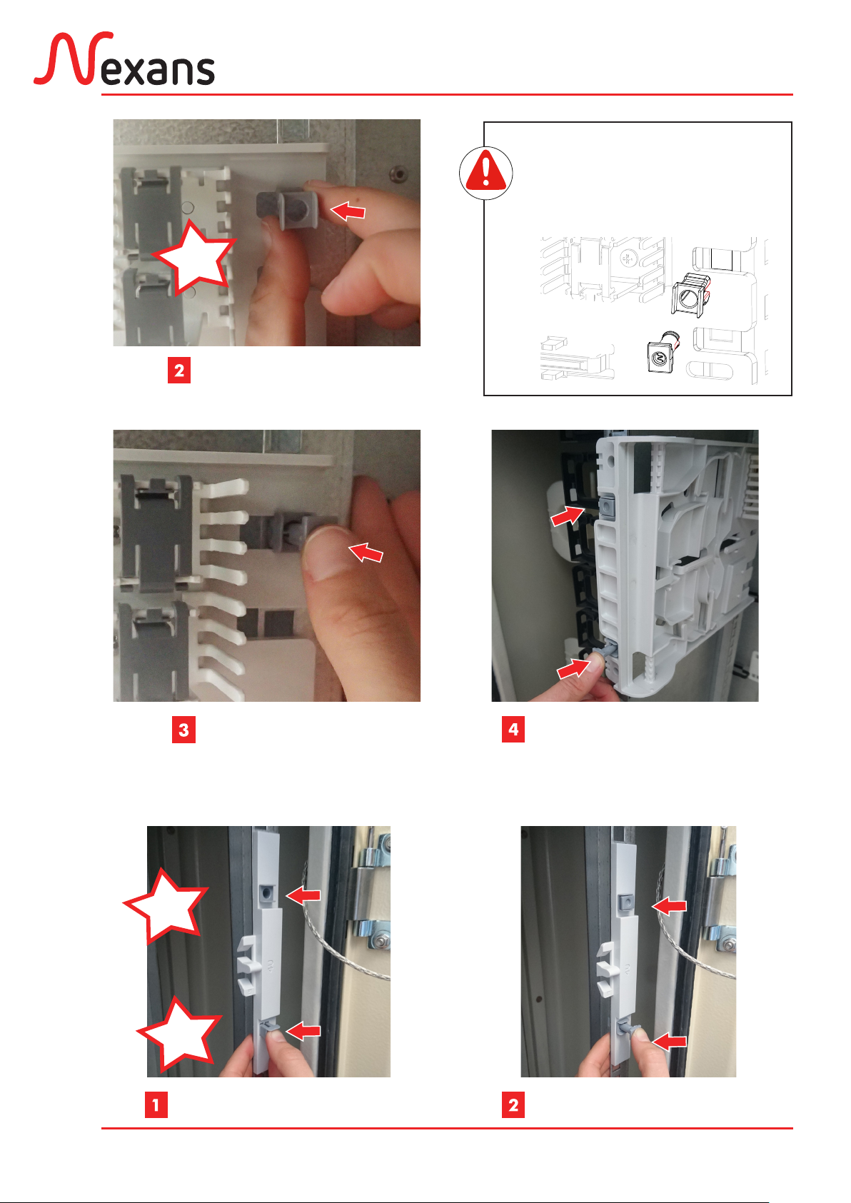
2.2. Mise en place du dormant
Installing the fixed chassis
Montant avant gauche
Left front frame
Standard
Standard
Dimension carrés
Squares dimension
Anneaux intégrés
Integrated spools
Click
Position de la douille et du
pion sur le montant avant
(gauche et droit).
Position of the socket and the
pawn in the front frame (left
and right).
Si l’armoire n’est pas conforme au
standard 19’’ £↕9,5mm, se reporter
au chapitre 7 (annexes).
If the cabinet is not compliant with
the 19’’ £↕9,5mm standard, refer to
the chapter 7 (annex).
Kit de fixation 19’’ standard
(£↕9,5mm). Standard 19’’ fixation kit (£↕9.5mm).
x5 x5 4U
a b c
Mise en place des douilles. Installing sockets.
Click
Enlever les appendices des pions
et des douilles.
Remove the links between sockets
and pawns.
ABS1570/A 10/26
XPLORER 144 - 3X48
Click
Sens de la douille et du pion
sur le montant arrière.
Position of the socket and the
pawn in the back frame.
Montant arrière
Back frame
Mise en place des pions. Installing pawns.
Montant arrière
Back frame
Montant avant gauche
Left front frame
2.3. Mise en place de la plaque de verrouillage
Installing the locking plate
Montant avant droit
Right front frame
Montant avant droit
Right front frame
Click
Click

ABS1570/A 11/26
XPLORER 144 - 3X48
Click
Ne pas déclipper le tiroir après
la mise en place.
Do not unclip the module after the
installation.
90°
90°
Angle de montage repéré par un index moulé
Mounting angle marked by molded index
2.4. Mise en place du battant
Installing the swiveling part
Click
Click

ABS1570/A 12/26
XPLORER 144 - 3X48
Click
Refermer le module
Close the swiveling part
3. RACCORDEMENT DU MEB 144
CONNECTION OF THE MEB 144
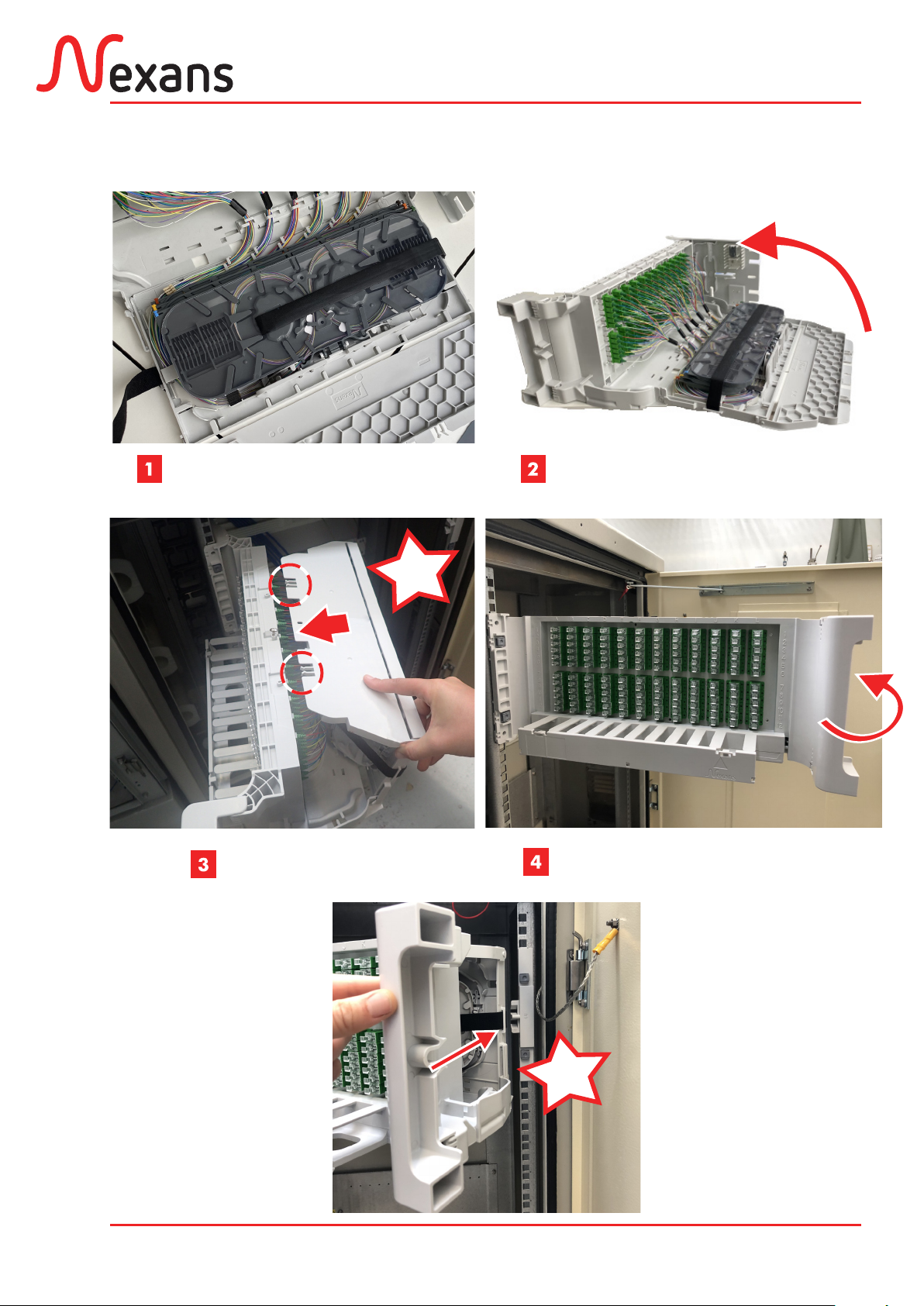
3.1. Accès à l’organiseur
Access to the organiser
105°
S’assurer du bon verrouillage
Ensure to correct locking
Ouvrir le battant
Open the swiveling chassis
Déclipper le capot
Unclip the cover
Veiller à bien dégager
les ergots pour
l’ouverture
Ensure to clear out the
ergots for the opening.

ABS1570/A 13/26
XPLORER 144 - 3X48
Faire pivoter la platine
Rotate the plate
Défaire le velcro de maintien
Release the velcro strip
3.2. Cheminement des loosetubes et de leurs fibres
Routing loosetubes and fibres
Tube Ø 5mm
1500mm
Loosetubes
Loosetubes
Peigne
Comb

ABS1570/A 14/26
XPLORER 144 - 3X48
Micromodules
Microbundles
Tube Ø 5mm
5mm
Fixation des tubes
Fixation of the tubes
Cheminement des fibres
Routing fibres
Pigtails
Peignes pour tubes
Combs for tubes
Peignes en mousse
Foam comb
Loose tubes

ABS1570/A 15/26
XPLORER 144 - 3X48
1
2
X2
max
Zone de lovage primaire optionnel
Optional primary coiling area
Cassette
Cassette
Raccords
Adaptors
Colonne façade
Front column
Lower
1
2
Middle
3
4
Upper
5
6
1-12 et 13-24
25-36 et 37-48
48-60 et 61-72
25-36 et 37-48
97-108 et 109-120
121-132 et 133-144
A et B
C et D
E et F
G et H
I et J
K et L
1
2
Identification de la cassette
Cassette identification
Option : il existe une version avec
tambour de lovage uniquement
pour bundles de fibres G657 (au
lieu des loosetubes en version
standard).
Optional: there is a version with a coiling
drum only for fibre bundles (instead of
the standard loosetubes.
ABS1570/A 16/26
XPLORER 144 - 3X48
4. FERMETURE DU MODULE
CLOSING THE SWIVELING CHASSIS
Remettre le velcro de maintien
Installing the velcro strip
Rabattre la platine et son capot
Rotate the plate and the cover
Clipper le capot
Clip the cover
Click
S’assurer du bon verrouillage
Ensure correct locking
Click

ABS1570/A 17/26
XPLORER 144 - 3X48
5. POSE D’UN CORDON
INSTALLING PATCHCORD
Ouvrir le volet de la goulotte et
connecter la fiche
Open the shutter of the cableway
and connect the patchcord
Insérer le cordon dans la goulotte
Insert the patchcord in the cableway
Passer le cordon dans l’anneau de guidage
Routing the patchcord in the spool clip
Refermer le volet
Close the shutter
En l’absence d’anneaux, se reporter
au chapitre 7 (annexes).
Without rings, refer to the chapter 7
(annex).
ABS1570/A 18/26
XPLORER 144 - 3X48
6. ÉLÉMENTS PARTICULIERS DE MAINTENANCE
SPECIAL PROCEDURES FOR MAINTENANCE
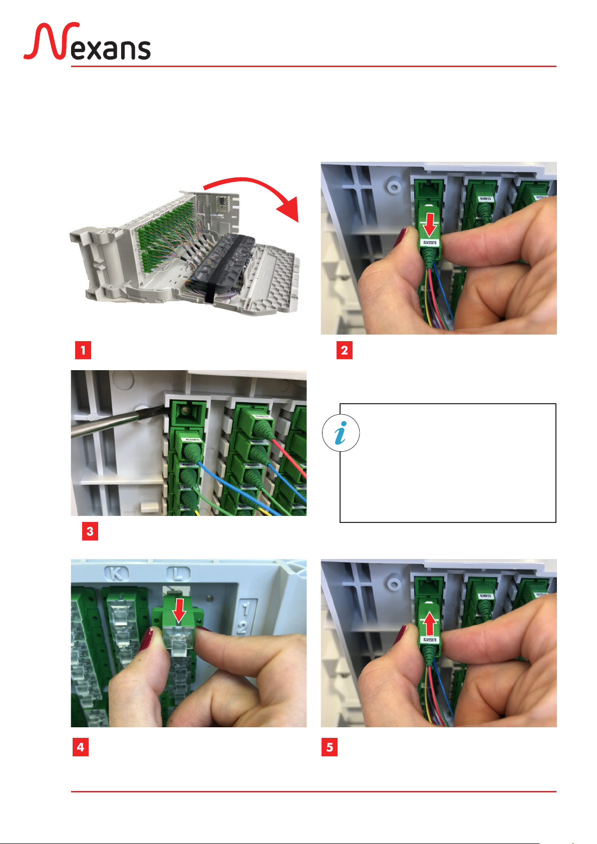
6.1. Remplacement d’un raccord
Adapter replacement
Déconnecter le pigtail et le cordonDéconnecter le pigtail et le cordon
Disconnect the pigtail
and the patchcord
Déclipper le capot et faire pivoter la platine
Unclip the cover anf rotating the plate
Faire pression sur le clip avec un
tournevis plat pour permettre le
retrait du raccord défectueux.
Release the clip with a flat screwdriver
to allow the removal of the defective
adaptor.
Déclipper l’ancien raccord par l’arrièreDéclipper l’ancien raccord par l’arrière
Unclip the old adaptor from behind
Clipper le nouveau raccord par l’avantClipper le nouveau raccord par l’avant
Clip the new adaptor from the front
Reconnecter le pigtail et le cordonReconnecter le pigtail et le cordon
Reconnect the pigtail and the patchcord

ABS1570/A 19/26
XPLORER 144 - 3X48
6.2. Principe de dépose du module
Module replacement
Retrait du pion du montant avant gauche
Remove pawn of the left front frame
Décâbler le module
Unwire the module
Ouverture du battant et retrait
du pion du montant arrière
Open the swiveling chassis and remove
the pawn from the back frame
Si l’accessibilité le permet, le
pion et la douille peuvent être
retirés à la main.
If there is accessibility, pawn
and socket can be removed by
hand.
Retrait de la douille du montant avant gauche
Remove socket from the left front frame
Vue de dessus
Top view
Retrait du pion et de la douille du verrouRetrait du pion et de la douille du verrou
du montant avant droit
Remove pawn and socket of theRemove pawn and socket of the lock
of the right front frame
Tirer le module
Pull the module

ABS1570/A 20/26
XPLORER 144 - 3X48
Description Qté /
Qty
Kit de fixation 19’’ (£↕8,3mm) :
(À approvisionner en supplément)
– Écrous cages (£↕8,3mm)
– Vis hexagonales à embase
19’’ fixation kit (£↕8.3mm):
(To be ordered separately)
–Cage nuts (£↕8.3mm)
–Hexagonal base screws
5
5
Kit de fixation 19’’ (£↕9,5mm) :
(À approvisionner en supplément)
– Écrous cages (£↕9,5mm)
– Vis hexagonales à embase
19’’ fixation kit (£↕9.5mm):
(To be ordered separately)
–Cage nuts (£↕9.5mm)
–Hexagonal base screws
5
5
Kit de fixation ETSI (£↕8,3mm) :
(À approvisionner en supplément)
– Verrou ETSI 7SU
– Écrous cages (£↕8,3mm)
– Vis hexagonales à embase
ETSI fixation kit (£↕8.3mm):
(To be ordered separately)
–ETSI 7SU lock
– Cage nuts (£↕8,3mm)
–Hexagonal base screws
1
5
5
Kit bobine :
(À approvisionner en supplément)
– Anneau bobine (Ø 50 mm)
– Support bobine
– Clip bobine
– Vis cylindriques large fendue
Spool kit:
(To be ordered separately)
–Spool (Ø 50mm)
–Spool support
–Spool clip
–Cylindrical slotted head
screw
1
1
1
1
7. ANNEXES
ANNEX
7.1. Autres kits
Others kits
d
e
f
g
e
e
d
h
j
i
k
Table of contents
Other Nexans Control Unit manuals

Popular Control Unit manuals by other brands


Laird
Laird BTM430 user guide

GIRBAU
GIRBAU HS-6008 Operation instructions

Cylon
Cylon ASPECT Nexus2 Hardware installation guide

Innovative Electronics
Innovative Electronics EMS 30 A H-Bridge quick start

Viessmann
Viessmann EA1 Installation instructions and operators manual

INTERSPIRO
INTERSPIRO PAC user manual


