NexPower NH-100AX-1 Series User manual

PLEASE READ THIS MANUAL CAREFULLY BEFORE INSTALLING OR USING THE MODULES
INSTALLATION MANUAL
Thin-Film Photovoltaic Module
NH-100AX-1 series
(NH-100AX-1_5A/ NH-100AX-1_4A/ NH-100AX-1_3A)
NexPower Technology Corp.
Ver. EU-E
Confidential
Table of Contents
1. INTRODUCTION ................................................................................ 1
2. WARNING AND SAFETY...................................................................1
3. LIMITATIONS ON USING NH-100AX-1 SERIES PV MODULE ........2
4. SITE SELECTION AND TILT ANGLE................................................4
5. INSTALLATION .................................................................................. 4
5-1 Limitation of Installation............................................................................. 4
5-2 Mounting Method ...................................................................................... 5
5-3 Mounting Structure.................................................................................... 6
6. WIRING .............................................................................................. 8
6-1 Series Wiring............................................................................................. 8
6-2 Parallel Wiring........................................................................................... 8
6-3 Inverter Selection ...................................................................................... 9
6-4 Cable Selection......................................................................................... 9
6-5 Bypass Diodes .......................................................................................... 9
6-6 Grounding ................................................................................................. 9
7. MAINTENANCE ............................................................................... 11
8. DISCLAIMER OF LIABILITY ........................................................... 11
9. APPENDIX 1 - Mechanical Specifications..................................... 12
10. APPENDIX 2 - Electrical Specifications ...................................... 13
11. APPENDIX 3 - Characteristic Curves ..........................................13
12. COPYRIGHT .................................................................................. 13
Confidential
NH-100AX-1 series 1 Ver. EU-E
1. INTRODUCTION
The installation manual describes the installation and maintenance instructions for NH-100AX-1
series PV module. This document also contains warning and safety information users should understand
thoroughly. Please read this manual carefully before the installation. The installation of the PV module
should only be performed by qualified specialists only. Before attempting to install, wire, operate, or
maintain the PV module, please carefully read and completely understand the information described in
this installation manual. This document does not constitute, express, or imply a warranty in any form.
2. WARNING AND SAFETY
PV module converts sunlight to electricity, when sunlight or light other source illuminates the
module surface. PV modules can produce high voltage and current which may cause serious
injury or even death. Extra attention is required to avoid “Electric Shocks”during usage.
Do NOT use PV modules near equipments or locations where flammable gases can be generated.
Do NOT disassemble the PV module or remove any component or label from the module.
Do NOT stand or step on the PV module, cables, connectors, or end caps.
Do NOT drop the PV module or allow objects to fall on PV module.
Do NOT artificially concentrate sunlight onto the PV module.
Do NOT connect the NH-100AX-1 series PV module with any other type of PV module.
Do NOT cut the cable attached on PV module then connect to another type of cable or connector.
Doing so will void the warranty.
When connecting cables, push the plus and minus connectors against each other while twisting
them until they are fully engaged.
Do NOT drill holes in the frame or on the glass of PV module. Doing so will void the warranty.
Do NOT use chemicals in cleaning the surface or back sheet of PV module. Do not let water
remain on the glass surface of PV modules for an extended period of time.
Please note, the back surface of PV module is not protected by glass and is vulnerable to sharp
objects.
Do not cover the water drain holes of the frame.
Always wear electrical insulating gloves, protective head gear, suitable eye protection, and safety
shoes while working on systems. Use only insulated tools during installation.
Do NOT work under rain, snow, or windy conditions.
Do NOT hang or carry PV module by the cable.
Do not pull or bend the cable using excessive force during wiring.
Do NOT touch the junction box or the output cables connectors with bare hands during installation,
regardless whether the PV module is connected to or disconnected from the system.
Mount the PV module onto the structure member with specified mounting structure. Make sure to
fasten bolts completely and lock in order not to loosen.
Do NOT damage the back sheet of PV modules while fastening the PV modules to a support rack.
Confidential

NH-100AX-1 series 2 Ver. EU-E
3. LIMITATIONS ON USING NH-100AX-1 SERIES PV MODULE
Please read these limitations carefully before installing or using the modules.
To stay within the warranty conditions of the NexPower NH-100AX-1 series PV modules, it is essential to
install the PV module with the following guidelines.
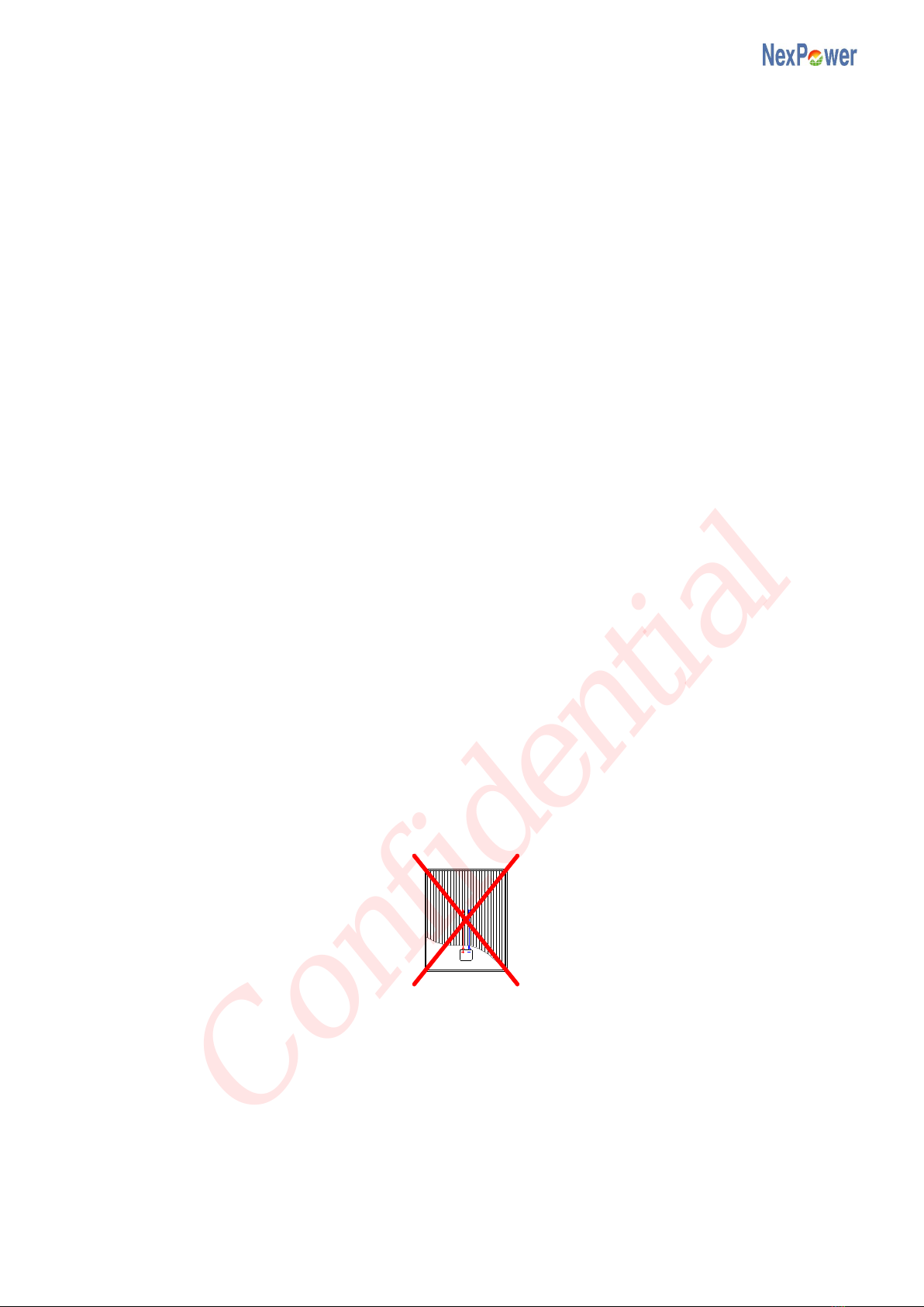
Do not install PV module upside down (junction box downward). Otherwise it will void the warranty.
The PV module is designed for vertical mount. Vertical mount is strongly recommended.
The PV module can either be installed vertical or horizontal, but must conform the following conditions.
Otherwise it will void the warranty.
i) The PV module should be installed in a manner which prevents shadowing effects (also partial
shading). The PV module must be sited where no shading occurs between the hours of 10 AM
and 2 PM.
ii) If the PV module is mounted horizontally, tilting angle must be more than 40 degrees, and front
row of PV array must not shade PV module.
iii) For on-ground installation, make sure to leave sufficient distance between PV module and the
ground to avoid the module being covered by accumulated water or snow.
a. Vertical Mount b. Horizontal Mount
Do not install the PV module where wind or snow exceeds its specified limit. The PV module have
been evaluated for a maximum positive or negative design loading of 2400 N/m2.
PV modules can withstand wind, snow, static or ice loads under conditions of different clamping
positions as listed below:
i) The clamp position (C) is from the end of the module to the centerline of the clamp or fixing plate.
ii) Free land installation
Mount position 120mm≦C≦200mm
Max. positive
design loading 2400 N/m2
Max. negative
design loading 2400 N/m2
iii) Roof installation
Mount position 120mm≦C≦200mm 150mm<C≦280mm
Max. positive
design loading 2400 N/m22400 N/m2
Max. negative
design loading 2400 N/m22400 N/m2
If the height of target roof is under 10m
a) The array should be at least 1m away from the edge of roof.
Tilt >40°
Confidential

NH-100AX-1 series 3 Ver. EU-E
b) The clamp position (C) within each module should be the same.
a. Mounting structure - A b. Mounting structure - B
The mounting clamp and fixing plate must meet the dimensions requirements.
i) Length A: 13mm ≦A ≦18mm
ii) Length B: B ≧40 mm
The torque on the clamp bolt or fixing plate bolt should be around 5-8 Nm. Otherwise it will void the
warranty.
It is not permitted to modify the module under any circumstances. Make sure the location and its
surroundings are free from such locations where corrosion may occur due to exposure to sea water,
salt breeze, corrosive matters (Ex. chemical factory, hot spring or volcano area emitting hydrogen
sulfide or ammonia gas).
Ensure the system design prevents a reverse current of no more than 5A will flowing through the PV
module. Otherwise it will void the warranty.
Grounding means with the PV module frames should comply with laws or electrical regulations of your
regions or countries.
It is essential to select inverters with the following features.
i) Inverters with galvanic isolation (transformer type) and grounded negative pole of the solar
generator strings; or,
ii) Specifically-designed transformer-less inverters (e.g. Sunways AT series).
Please refer to Chapter 4 ~ Chapter 7 for more detailed information.
A
B
Confidential
NH-100AX-1 series 4 Ver. EU-E
4. SITE SELECTION AND TILT ANGLE
The PV module generates power when it is illuminated by sunlight. In order to gain maximum power,
the PV module should face directly towards the sun. The PV module should be installed to typically
face south in the northern hemisphere and north in the southern hemisphere.
In most applications, the PV module should be installed in a location without shading throughout the
year. It is necessary to choose a site where no trees, buildings, or obstructions could cast shadows on
the PV module.
If it is not possible to place the PV module in a shadow-free location, the PV module must be sited
where no shading occurs between the hours of 10 AM and 2 PM. Otherwise it will void the warranty.
In systems that are configured with multiple rows of angled PV modules, the rows should be spaced far
enough apart to minimize the impact of rows shading other rows during the course of the day. This
distance is dependent on the latitude at which the system is installed.
It is not permitted to modify the module under any circumstances. Make sure the location and its
surroundings are free from such conditions.
i) Locations where corrosion may occur due to exposure to sea water, salt breeze, etc.
ii) Locations where the PV module may be exposed to corrosive matters (Ex. chemical factory,
domestic animals hut, hot spring or volcano area emitting hydrogen sulfide or ammonia gas)
In some installations, the PV module is mounted at a tilt angle which is measured between the PV
module and the horizontal ground. For grid-connected installations where PV modules are attached to
a permanent structure, it is recommended to tilt PV module at the angle equal to the site’s latitude.
Adjust the PV module orientation to face the sun directly so it will generate the maximum power.
It is recommended to set the tilt angle above 10-15 degrees so that rain can flush away the
accumulated dust on PV module surface. If lower, a periodic cleaning maintenance may be necessary.
5. INSTALLATION
5-1 Limitation of Installation
The support structure for the PV module must be engineered to withstand the anticipated wind and
snow loads. Additionally, other forces may need to be considered according to local standards and
regulations.
Do not install PV module upside down (junction box downward). Otherwise it will void the warranty.
The PV module is designed for vertical mount. Vertical mount is strongly recommended.
The PV module can either be installed vertical or horizontal (Fig. 1), but must conform the following
conditions. Otherwise it will void the warranty.
i) The PV module should be installed in a manner which prevents shadowing effects (also partial
shading).
ii) The PV module must be sited where no shading occurs between the hours of 10 AM and 2 PM.
iii) If the PV module is mounted horizontally, tilting angle must be more than 40 degrees, and front
row of PV array must not shade PV module.
Confidential

NH-100AX-1 series 5 Ver. EU-E
a. Vertical Mount b. Horizontal Mount
Fig. 1 PV Module Mounting Configuration
Please refer to Chapter 2 (WARNING AND SAFETY) for more detailed limitation items.
5-2 Mounting Method
PV modules can be mounted on ground, roof, and/or pole by using bolts, clamps, or fixing plates.
In most installations a clearance of 5 mm between modules is necessary to accommodate thermal
expansion.
For proper operation and to avoid damage from condensation, the PV module requires an adequate
flow of air across the rear surface. While installing PV modules, ensure sufficient distance between the
rear of PV module and the mounting surface to allow the air flow.
In case of on-ground installation, be sure to leave sufficient distance between PV module and the
ground to avoid the module being exposed to standing water or snow.
Fasten bolts and nuts properly with the stipulated torque. Please refer to “B- clamps & Fixing Plates”
on Page 5.
A - Mounting Holes
The PV module has four Φ10 mm holes in its frame for mounting purpose. PV modules may be
fastened to a support by using bolt holes that are at the bottom of the frame with stainless M8 bolts,
washers, spring washers, and nuts (Fig. 2).
Do not damage the rear surface of PV modules while fastening PV modules by bolts.
Fig.2 Mounting method – bolt
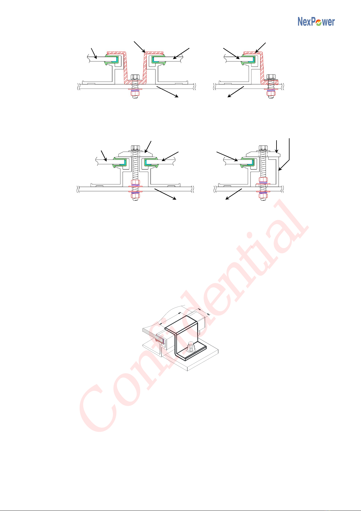
B - Clamps & Fixing Plates
The PV module can be mounted by using clamps and fixing plates (Fig. 3, 4).
Bolt
Frame
Washer
Washer
Nut
Structure member
Spring Washer
Tilt >40°
Confidential
NH-100AX-1 series 6 Ver. EU-E
Fig.3 Mounting method – clamp
Fig.4 Mounting method – fixing plate
The torque on the clamp bolt or fixing plate bolt should be around 5-8 Nm. Otherwise it will void the
warranty.
The mounting clamp and fixing plate must meet the dimensions requirements (Fig. 5).
i) Length A: 13mm ≦A ≦18mm
ii) Length B: B ≧40 mm
For more detailed or specific recommendations, please contact your PV system dealer or module
provider.
Fig.5 Clamp dimension definition
5-3 Mounting Structure
The PV modules may be mounted using clamps or fixing plates on long edge of PV module, which
would be perpendicular (Fig. 6-a) or parallel to array racks (Fig. 6-b).
The PV module must be supported along the length of the long edge. The array racks must support the
bottom of the modules and must be continuous pieces (no breaks in the rack).
When selecting the material for the assembly system, pay attention to the electrochemical series
(avoidance of contact corrosion between different materials).
Mounting position is depended on installation method:
Clamp
PV module
PV module
Clamp
Support structure
PV module
Fixing plate
Fixing plate
Support structure
PV module
A
B
Confidential

NH-100AX-1 series 7 Ver. EU-E
To keep the warranty validated on NexPower NH-100AX-1 series PV modules, it is essential to install
the PV module according to the following guidelines.
i) The clamp position (C) is from the end of the module to the centerline of the clamp or fixing plate.
ii) Free land installation
a) When 120mm ≦C ≦200mm, PV modules can sustain max. 2400 N/m2loading on the
front surface or on the back surface of PV modules.
iii) Roof installation
a) When 120mm ≦C ≦200mm, PV modules can sustain max. 2400 N/m2loading on the
front surface or on the back surface of PV modules.
b) When 150mm <C ≦280mm, PV modules can sustain max. 2400 N/m2loading on the
front surface of PV modules.
c) When 150mm <C ≦280mm and the height of target roof is under 10m, PV modules can
sustain wind force parallel to the ground with max. 2400 N/m2wind pressure from the back
surface of PV modules.
d) The array should be at least 1m away from the edge of roof.
e) The clamp position (C) within each module should be the same.
a. Mounting structure - A
b. Mounting structure - B
Fig.6 Mounting structure (unit: mm)
PV module
Bolt & Nut
Structure member
Aluminum frame
Clamp
Confidential
NH-100AX-1 series 8 Ver. EU-E
6. WIRING
The PV module has two sunlight resistant output cables, and each is terminated with a Multi-Contact
compatible connector. The positive terminal has a female connector, and the negative terminal has a
male connector.
Do not cut the cable attached to PV module in order to connect to another type of connector or cable.
Connecting PV modules in series would increase voltage, while connecting in parallel would increase
current. In order to design an adequate PV system, PV modules should be connected in series and/or
in parallel depending on specifications of inverters or other pertinent equipments.
While connecting several strings in parallel, it is necessary to keep equivalent quantity of PV modules
to each parallel string. If connected incorrectly, PV modules will become damaged.
All system wiring must conform to local electrical codes.
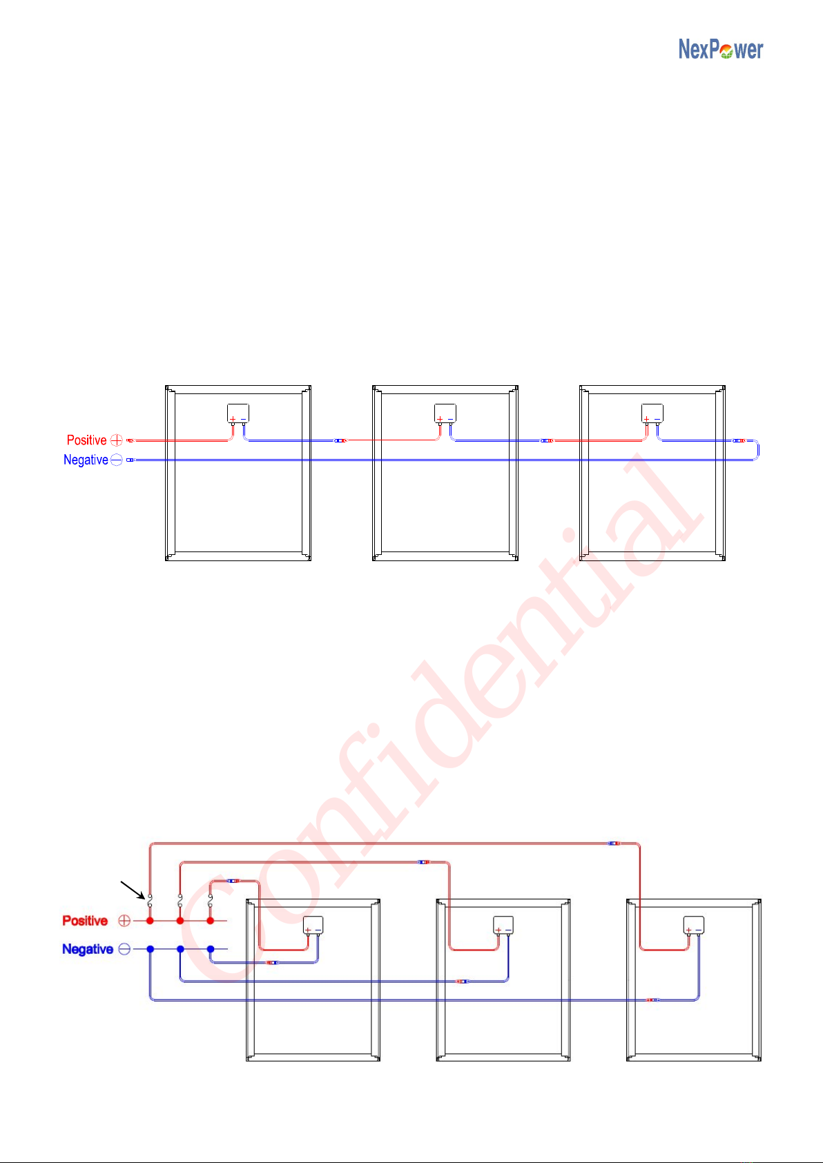
6-1 Series Wiring
Fig.7 Series connections
PV modules can be wired in series to increase voltage. Connect cables from the positive(+)/ negative(-)
terminal of one module to the negative(-)/ positive(+) terminal of the next module (Fig. 7).
When several PV modules are connected in series, the voltage and current are as below:
Vtotal = V1+ V2+ … .. + Vn
Itotal = I1= I2= … .. = In
n : number of series PV modules
It is recommended to multiply the Voc listed on the module label by a factor of 1.25, and make sure the
system voltage must not exceed a maximum of 600V. Otherwise it will void the warranty.
6-2 Parallel Wiring
Fig.8 Parallel connections
Fuse
Confidential

NH-100AX-1 series 9 Ver. EU-E
PV modules can be wired in parallel to increase current. Connect cables from the positive(+)/
negative(-) terminal of one module to the positive(+)/ negative(-) terminal of the next module (Fig. 8).
When several PV module strings are connected in parallel, the voltage and current are as below:
Vtotal = V1= V2= … .. = Vn
Itotal = I1+ I2+ … .. + In
n : number of series strings
Please be noted that the short-circuit current of system is calculated by multiplying the Isc listed on the
module label by the number of source circuits operating in parallel. Use this value and multiply by 1.56
to determine the conductor capacities and fuse sizes connected to the module output.
Ensure the system design prevents a reverse current of no more than 5A will flowing through the PV
module. Otherwise it will void the warranty.
Parallel configuration is not limited in case of taking proper measure (e.g. fuse for protection of module
and cable from overcurrent, and/or blocking diode for prevention of unbalanced strings voltage) to
block the reverse current flow.
6-3 Inverter Selection
To stay within the warranty conditions of the NexPower NH-100AX-1 series PV modules, it is essential
to select inverters with the following features.
i) Inverters with galvanic isolation (transformer type) and grounded negative pole of the solar
generator strings; or,
ii) Specifically-designed transformer-less inverters (e.g. Sunways AT series).
The warranty will be voided if failing to follow the above instructions.
For more detailed or specific recommendations, please contact your PV system dealer or module
provider.
6-4 Cable Selection
It is very important to use the proper cable with a minimum wire gauge approved for usage at the
maximum short circuit current. Smaller gauge cables and connectors can become overheated under
high currents.
The cables selected should have a temperature rating higher than 90˚C.
Series and parallel wiring should use the same connectors as of the PV modules.
6-5 Bypass Diodes
Buildings, trees, or obstructions around PV modules can cast shadows on PV modules. Current forced
through shaded part of PV modules causes additional heating and severe loss of power.
In order to avoid this condition which may impair PV module, NH-100AX-1 series module is equipped
with factory-installed bypass diodes.
Rated value
Repetitive Peak Reverse Voltage 1000 V
Maximum Average Forward Current 5 A
6-6 Grounding
Grounding method must comply with laws or electrical regulations. Please confirm electrical codes in
the region where the PV system is installed. In some specific countries, if coupled with transformer
type inverters, grounding of frame can be omitted.
Confidential
NH-100AX-1 series 10 Ver.
EU-E
Each PV module must be grounded using the grounding holes found on the frame. The PV module has
four Φ3.5mm holes in the frame for grounding purpose. Select at least one grounding hole according
to PV module mounting mode.
Must apply equipment grounding at the same electrical potential level to all PV modules.
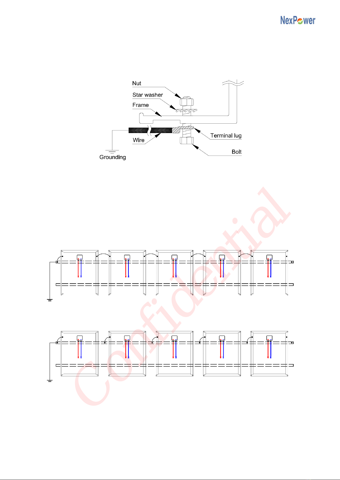
Grounding cables must be bolted or screwed with star washers (Fig. 9).
Fig.9 Grounding connection of the PV module
When connecting in series, PV modules either connect to the structure members by attaching wires to
the ground holes on the frames or directly bind with the structure member at adequate positions to
deploy the grounding method at the designated equipment grounding spot. Grounding must be done
on the first or the last PV module of each string (Fig. 10). Otherwise it will void the warranty.
Grounding method - A
Grounding method - B
Fig.10 Ground method of the PV array
The negative pole of solar generator strings connected to the inverter must also be grounded (Fig. 11).
Otherwise it will void the warranty.
Structure
member
Structure
member
Grounding
Grounding
Confidential

NH-100AX-1 series 11 Ver. EU-E
Fig.11 Negative pole grounding method
7. MAINTENANCE
The PV modules are designed to last for extended period of time thus require very little maintenance.
When dirt accumulates on the surface of PV module and becomes excessively built-up, power output
may decline. When this situation occurs, cleaning the module surface is necessary but only with a soft
cloth and mild detergent water. Before washing, please wear electrical insulting gloves to avoid
electrical accidents. Protect yourself against any possibility from accidents during maintenance. If
cleaning the back of the module is required, take utmost care to avoid penetrating the back side
materials.
Check annually and carefully to ensure for fixed mounting hardware and tightened wiring. Any loose
connections or parts may cause damages in modules or arrays.
If any problem is found, please contact your local PV system dealer for professional service.
8. DISCLAIMER OF LIABILITY
NEXPOWER does not assume responsibility and expressly disclaims liability for loss,
damage, or expense arising out of or in any way connected with such installation, operation, use,
or maintenance of the PV module. No responsibility is assumed by NEXPOWER for any
infringement of patents or other rights of third parties which may result from use of the module.
NEXPOWER reserves the right to make changes to the product, specifications or installation
manual without prior notice.
Inverter
Grounding
Confidential

NH-100AX-1 series 12 Ver.
EU-E
9. APPENDIX 1 - Mechanical Specifications
Items Specification
Length [mm] 1414
Width [mm) 1114
Thickness [mm] 35.3
Weight [kg] 20.5
(Front View) (Back View)
(Cross-section View)
A-A Section B-B Section
Confidential
NH-100AX-1 series 13 Ver.
EU-E
10. APPENDIX 2 - Electrical Specifications
Grade 5A 4A 3A
Condition Stable Initial Stable Initial Stable Initial
Nominal Power (± 5%) [W] 105 139.1 100 132.5 95 125.8
Open Circuit Voltage [V] 102 104.6 101 103.6 100 102.6
Short Circuit Current [A] 1.68 1.75 1.65 1.72 1.62 1.69
Maximum Power Voltage [V] 77.2 88.9 75 86.3 73 84.0
Maximum Power Current [A] 1.36 1.57 1.33 1.53 1.3 1.50
Maximum System Voltage [V]
1000
Maximum Reverse Current [A] 5
Temperature Coefficients:
Nominal Power -0.2 %/˚C
Open Circuit Voltage -0.34 %/˚C
Short Circuit Current 0.09 %/˚C
Data above represent stabilized values at Standard Test Conditions(STC) [Irradiance: 1000 W/m2,
Spectrum: AM1.5, Cell temperature: 25°C].
All electrical ratings have a tolerance of ±10% unless specified otherwise. Specifications are
subjected to change without notice.
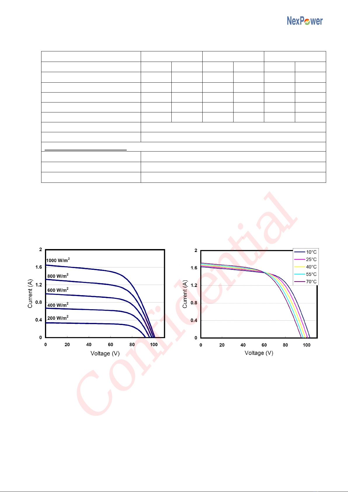
11. APPENDIX 3 - Characteristic Curves
Current v.s. Voltage Characteristic
(cell temperature:25°C)
Current v.s. Voltage Characteristic
(Irradiance:1000 W/m2)
12. COPYRIGHT
All contents in this manual, including, without limitation, all text, logos, images, photos,
graphics, designs and any other intellectual property rights related to these contents are owned
by NEXPOWER Technology Corporation. Except to the extent expressly permitted by applicable
law, no contents in this manual may be used, copied, modified, translated, distributed or
otherwise utilized without the prior written consent of NEXPOWER Technology Corporation.
Confidential
This manual suits for next models
3
Table of contents


