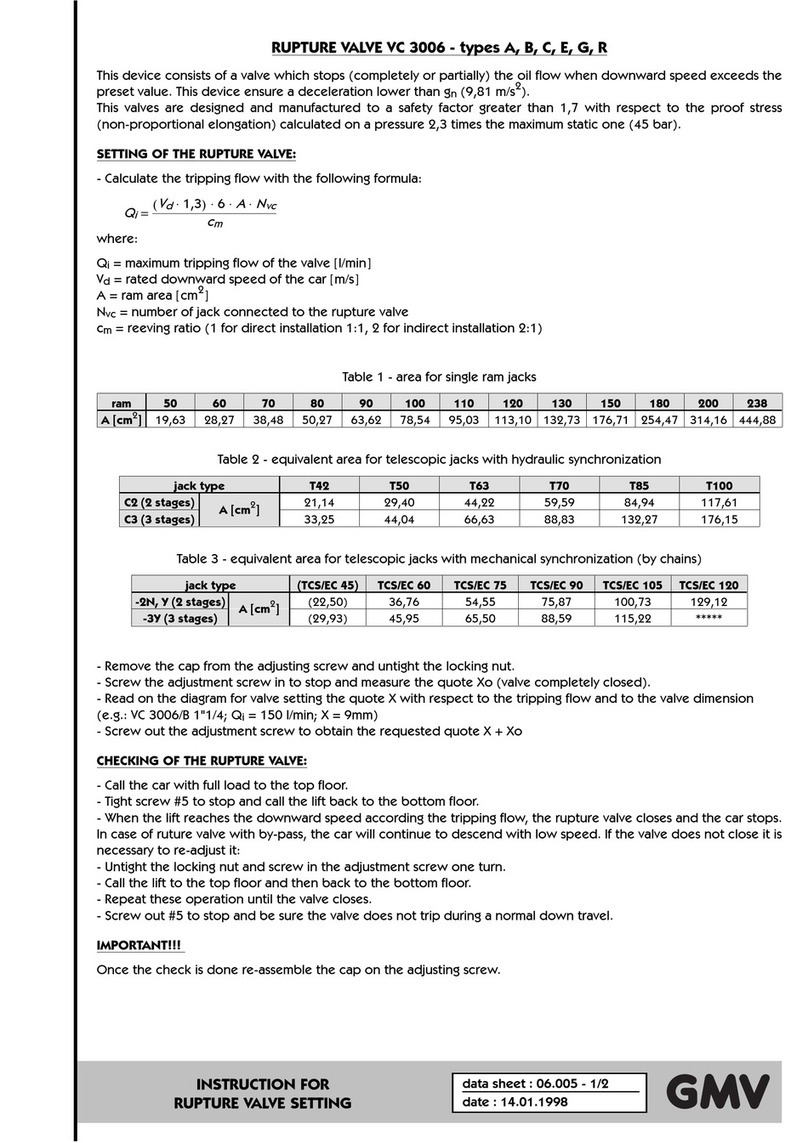
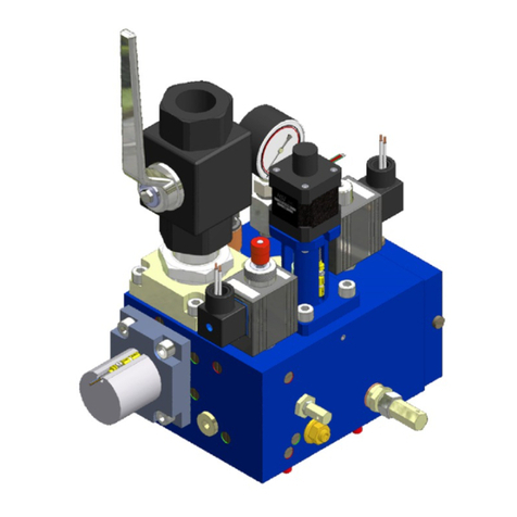
GMV NGV A3 Quick start guide

GMVSPA
FLUIDDYNAMICS EQUIPMENTS
AND COMPONENTS FORLIFTS
UNI ENISO9001
Certified Company
1.05
ENG
English
NGVA3 VALVE
NGVA3VALVE MANUAL
INSTALLATION, USE AND MAINTENANACE
10991 483 EN
AVAILABLE WITH TANK TYPE
GL, F1, T2, T3, T4, MRL-T, MRL-H

10991 483 EN - 21.12.2011
ENG
1.05 2 / 46 NGV A3 VALVE MANUAL
INSTALLATION, USE AND MAINTENANCE
INDEX
0GENERALSECTION 5
0.1 INTRODUCTIONINFORMATIONS 5
0.1.1DEFINITIONS 5
0.1.2TERMSAND SYMBOLSUSED 5
0.1.3RULES REFERENCE 5
0.2 DOCUMENTS RELATEDWITHINSTALLATION 5
0.3 SAFETYPRECAUTIONDURINGINSTALLATION 5
0.4 TOOLING 5
0.5 GENERALORDERS 6
1FEATURES AND REQUIREMENTS 7
1.1 THE NGVA3 VALVE 7
1.2 THE FLUID 7
1.3 HOWTHE NGVA3 WORKS 8
1.4 THE DOUBLE SAFETY 9
1.5 MAIN FEATURES 9
2INSTALLATIONOPERATIONS 10
2.1 HYDRAULICCONNECTIONS 10
2.1.1MINIMUMDIMENSIONSAND HOLES FOR POWER UNIT 10
2.1.2INPUTAND OUTPUT -POWER UNITSIDE 11
2.2 HYDRAULICCIRCUIT 11
2.3 ELECTRICALCONNECTIONS 12
2.3.1CONTROLPANELREQUIREMENTS 12
2.3.2INTERVENTION TIME 12
2.3.3 FAULT SCHEMAS 13
2.4 OPERATIONS PRELIMINARYTOCONNECTION 13
2.5 SCHEMAS OF THE CONNECTIONS TOCONTROL PANELS 14
2.5.1MAIN SCHEMA 14
2.5.2CONNECTION SCHEMAS FOR SIGNALS 15
2.5.3CONNECTION SCHEMAS FOR POWER 15
2.6 CONNECTIONS TOTHE TERMINAL 16
2.7 CONNECTIONS TOTHE CARD 16
2.8 CONNECTIONOF HYDRAULICPIPES 17
2.8.1CONNECTION WITH FLEXIBLEHOSE 17
2.8.2CONNECTION WITH ARIGID PIPE 17
3NGVA3CONTROLBOARD 18
3.1 ELECTRICALFEATURES 18
3.2 PERFORMANCES 18
3.2.1SIGNALLERS 18
3.3 CONNECTIONS 19
3.3.1CONTROLPANELINTERFACE 19
3.3.2VALVE INTERFACE 20
3.3.3USER INTERFACE 21
3.4 SIGNALS AND COMMANDS SEQUENCE 22
3.4.1UPWARD DIAGRAM 22
3.4.2DOWNWARD DIAGRAM 23
3.5 DECELERATIONDISTANCES 24
4ADJUSTMENTSAND TEST 25
4.1 ADJUSTMENTOF THE OVERPRESSURE VALVE (OPP/MPS) 25
4.2 RAMPRESSURE ONTHE VSMA ADJUSTMENT 26
4.3 PIPE RUPTURE VALVE (VC) TEST 26
4.4 TESTOF DEVICES THATPREVENTUNCONTROLLEDMOVEMENT 26
4.4.1PREREQISITES 26
0.1.1 26
4.4.2TESTIN UPDIRECTION 27
4.4.3TESTIN DOWN DIRECTION 27
4.5 TESTOF THE DOUBLE SAFETYSYSTEM 28
4.5.1SIMULATION OFTHE VRP FAULT 28
4.5.2SIMULATION OFTHE VB FAULT 29
4.5.3TEST OFTHEMONITORING SYSTEM 29
4.6 FAULTSIMULATIONONOUTPUT RDY AND RUN 30
4.6.1TESTRUN ALWAYS ON 30

10991 483 EN - 21.12.2011
NGV A3 VALVE MANUAL
INSTALLATION, USE AND MAINTENANCE 3 / 46
1.05
ENG
4.6.2TESTRDY ALWAYS OFF 30
4.6.3TESTRUN ALWAYS OFF 30
4.6.4TESTRDY ALWAYS ON 30
4.6.5EXITRUN-RDYTEST 30
5PROGRAMMING 31
5.1 SYSTEMPARAMETERS 31
5.2 COMPLETE MENÙ 32
5.3 MENÙ 33
- 1- DIAGNOSTICS 33
- 2- ALLARM 33
- 3- ALARMAND FAULTRESET 33
- 4- ADJUSTMENTS 34
-5- SETTINGS 35
- 6- UPWARD PARAMETERS 36
- 7- DOWNWARD PARAMETERS 36
- 8- OUTPUTFUNCTIONS 37
- 9- TEST 37
- 10 - ADVANCED PROGRAMMING 38
5.4 CHARTOF OUTPUTPROGRAMMABLE FUNCTIONS 38
5.5 CHARTOF FAILURES 39
5.6 ACCESSORIES 39
6MAINTENANCE AND FAULTANALYSIS 40
6.1 PROGRAMMEDMAINTENANCE 40
6.2 PERIODICALMAINTENANCE AND CHECKS TABLE 40
6.3 MAINTENANCE SCHEDULES 40
6.4 FAULT ANALYSIS 42
6.4.1TROUBLESHOOTING 43
6.5 ADJUSTINGTHE SENSORS 45
6.5.1SENSOR S1 45
6.5.2SENSOR S2 45
6.5.3SENSOR S3 45
7CERTIFICATES 46
ENG
All rights reserved.
Anykind of exploitation inanyformand byanymeans is forbidden without awritten permission of GMV Spa.
GMV Spa, withintechnicalor manufacturing progress, reserves the right tomodifyparts or this manualwithout notice.
Drawings, descriptions and dataincluded inthis manualare indicatives.
For all the datanot included inthis manualrefer tothe documents of anysinglepart.
Toguarantee the products security, do not usespare parts not genuine or not approved by GMV Spa.
GMV Spa will not assumeanyresponsibilityif the instructions included inthis manualare not observed.
/c2
DT21/12/2011 2C
CR 21/12/2011 2c6
GF 21/12/2011
Information and support:
FLUIDDYNAMICS EQUIPMENTS AND
COMPONENTS FORLIFTS
UNI ENISO9001
Certified Company
GMVSPA
ViaDon Gnocchi, 10 -20016 PERO–Milano (Italy)
TEL. +39 02 33930.1-FAX+39 02 3390379
http://www.gmv.it -e-mail: info@gmv.it

10991 483 EN - 21.12.2011
ENG
1.05 4 / 46 NGV A3 VALVE MANUAL
INSTALLATION, USE AND MAINTENANCE
Mainacronyms and abbreviations
# Description
1 Pressuresafetyvalveadjustment (pressurelimiter)
2 Pressure safetyvalve adjustment (hand pump)
3 Rampressureadjustment (only2:1acting jacks)
4 Shut-off valvefor pressuregauge exclusion
5 Screwfor rupturevalvetest
AF Valvetoprevent ropesslacking
BOX Interface box (NGVA3/ Control panel)
C1 Chamber of the VRP
C2 Inlet chamber
C3 VB outlet chamber
C4 Chamber of the VRP pilot spool
CARD NGV A3control card
D Downwardsignal
DN Downward
FLT Filter
ISP Inspection gauge fitting
J Jack
K Non-returnvalve
M1 Spool of the VRP
MAN Pressuregauge
ML Manual lowering button
M, MP Motor / pump
MPS Maximumpressurespool
NGV-A3 NGV A3Valve(Complete)
OFF Not powered
ON Powered
OPP MPS pilot valve
P VRP pilot spool
PAM Hand pump
PT Pressuretransducer
RDY Ready- Readysignal (cardoutput tocontrol panel)
RO Oil heating resistance
RT Motor thermistors
RUN Run - Start signal (cardoutput tocontrol panel)
S1 (VRP) Sensor tocontrol the VRP closing
S2 (VBC) Sensor tocontrol the VB closing
S3 (VBO) Sensor tocontrol the VB opening
SM Stepping motor
TO Oil thermostat
TT Temperaturetransducer
UP Upward/ Up- command of starting upward(cardtocontrol panel)
V0 Speed : high
V1 Speed : medium
V2 Speed : inspection
VAL ValveNGVA3(Valveonly)
VB Main flowadjustment valve
VC Rupturevalve
VMD Downwardsolenoid valve
VR Non-returnvalve(flow)
VR1 Non-returnvalve(inlet)
VR2 Non-returnvalve(outlet)
VRP Non-returnvalve- controlled
VS Upwardsignal
VS1, VS2 Pressuresafetyvalve
VSMA Lowering valvemanual / electrical

10991 483 EN - 21.12.2011
NGV A3 VALVE MANUAL
INSTALLATION, USE AND MAINTENANCE 5 / 46
1.05
ENG
0 GENERAL SECTION
0.1INTRODUCTION INFORMATIONS
0.1.1DEFINITIONS
In thismanualare used the definitionsin EN81-1, EN81-2: Safetyrulesforthe construction and installation of
lifts, EN81-28: Remote alarmson passengerlifts, EN1050: Safetyofmachinery-Principlesforrisk
assessment, ISO3864: Safetycolours and safetysigns, and the following apply:
0.1.2TERMSANDSYMBOLSUSED
NOTE
Indicatesinformation which contentsmust be seriouslytaken in consideration.
WARNING
Indicatesthat the described operation islikelyto cause, damagesto the systemorphysicaldamages
ifperformed without complying with the safetystandards.
0.1.3RULESREFERENCE
Forall definitionsnot included in thismanualplease referto rulesand locallawsin force, following,
particularly:
EN 81-2: Safetyrulesforthe construction and installation oflifts,
EN 1050: Safetyofmachinery-Principlesforriskassessment,
ISO3864: Safetycolours and safetysigns.
0.2DOCUMENTS RELATEDWITH INSTALLATION
The documentsto use forthe installation are those required bythe EN81-2:1998 and bythe rulesin force,
particularlythe following:
- THIS INSTALLATIONMANUAL
- WIRINGAND HYDRAULICDIAGRAMS (EN81-2:1998 16.2 A)6 AND 7).
All the documentation fora correct and safe installation, must be stored bythe installation responsible.
Please rememberthat thisdocumentation isconsidered part ofthe plant and must be complete, well stored
and unabridged in everypart.
In orderto maintain the readability, the documentation shouldn’t be damaged and shouldn’t have missing
parts. Moreover, do not tearordeteriorate sheetsduring consulting.
0.3SAFETYPRECAUTION DURINGINSTALLATION
WARNING
Before start all kind ofinstallation operation.
ALWAYSverifythat althe safetydevices, mechanicalorelectrical, are active and working properly.
0.4TOOLING
Use standard building-yard tooling forthe installation.

10991 483 EN - 21.12.2011
ENG
1.05 6 / 46 NGV A3 VALVE MANUAL
INSTALLATION, USE AND MAINTENANCE
0.5GENERAL ORDERS
The valvesshall be maintained in good working orderin accordance with the European Standards.
To thiseffect, regularmaintenance ofthe installation shall be carried out, to ensure, in particular, the safety
ofthe installation.
The safetyofan installation shall take into account the abilityto be maintained without causing injuryor
damage to health.
Regularmaintenance ofthe installation shall be carried out to ensure the reliabilityofthe installation.
The access and the associated environment shall be maintained in good working order.
The competence ofthe maintenance person within the maintenance organization shall be continuously
updated.
NOTE
We informthe ownerofthe installation that the qualification ofthe maintenance organization needsto
be in conformitywith the rulesapplicable in the countryin which the installation operates; ifno rules
exist, the qualification can be ensured bya certified EN ISO9001 qualitysystemsupplemented if
necessaryto take into account the specificfeaturesofthe installation.
¥"

10991 483 EN - 21.12.2011
NGV A3 VALVE MANUAL
INSTALLATION, USE AND MAINTENANCE 7 / 46
1.05
ENG
1 FEATURES AND REQUIREMENTS
1.1THENGVA3VALVE
The NGVA3 Valve with:
·the newFluitronicdigitaltechnology.
·the “Stepping System”device
·the possibilityto use ecologicalfluid ortraditionalmineraloil
·the working pressure between 12 and 45 bar
Guarantees:
- Increased reliabilityofthe controlsystem
- Best performance
- Reduction ofcosts
- Reduction ofthe installed power(up to 20%)
- Reduction ofconsumptionsup to 40%(*)
- Reduction ofthe traveltime
- Reduced use ofheat exchangers
- Constant downward speed regardless ofthe load
- Compliance with variousregulatoryand environmentalrequirements
(Ex. compliance with the Directive 2006/118/EC on the environment)
- More safetythanksto double lock, alreadyintegrated in the product
conformsto the rule EN 81-2:2010
Offer:
- Idealsolution forrenovation and MRL systems
- The most advanced systemofcontrolforlift
- Technologyin line with the latest trendsin the controlfield
- Speed up to 1 m/s
- Downward speed greaterthan the upward up to +20%
- Ride comfort comparable to a VVVFelectricand no consumption in
standbymode
- Maintenance speed adjustable
(*)Maximumvalue reached underoptimalconditionsand in combination
with otherproductsGMV
- The driving option
INTERNAL FEED BACK (CAR LOAD / TEMPERATURE)
The choice to immediate savings, interfaced with all, existing and
newsystems
Not require encoder, reduce consumption up to 20%*
The valve, stored the operating characteristics, reading changing of
pressure and temperature, make the appropriate correctionsto
obtain carspeed profileswith lowdeviationsfromthe idealprofile.
*Compared to a traditionalvalve
1.2THEFLUID
GMV use and recommend an hydraulicfluid ISOVG46 that :
·Thanksto classification ascategoryHEES, asrule ISO-UNI 6743-4 and
itsbiodegradabilityindex>90%, according to standard CEC L33-A-
93, isacceptable froman environmentalpoint ofview.
·Thanksto the syntheticbase (ISOVG46 )and itsviscosityindex
(>140), higherthan the traditionalmineraloil, allowing greaterstability,
ensuring betterperformance against wearand aging on systemsas
liftsforpersonsand goods, in accordance with the environmental
directive 2006/118/EC.
·Thanksto a flash point above 220°C compared to the 140°C ofthe
traditionalmineraloil it issaferand reducesthe riskoffire.

10991 483 EN - 21.12.2011
ENG
1.05 8 / 46 NGV A3 VALVE MANUAL
INSTALLATION, USE AND MAINTENANCE
1.3HOWTHENGVA3WORKS
The valve NGVismade with a non-return valve VR, a controlspoolVB controlled bya stepping motorand by
a systemwith pilot operated non-return valve VRP-P
(moved in opening bythe electro-valve VMD)
Valve VR It isa valve that prevent , during the downward, the oil inlet to the pump.
It forcesthe oil that comesfromthe VRPC2 to pass through the spoolVB and then in the
C3 and in the tankT1.
Valve VRP-P It isthe pilot operated non-return valve, requested byrules.
During upward the valve worksonlyasON/OFF, the spoolVRPopensorcloses
depending on the oil that comes. Itsposition isdetermined bythe ratio between the
pressure that developsin the chamberC2 and the one that occurs in chamberC1
During downward, instead, it opensthe oil wayto the valve block(chamberC2).
Itsopening ismade bythe pushing ofthe piston Pthat isopened bythe pilot operated
valve VMD
Spool VB It’sthe main part ofthe controlblock.
It adjuststhe oil quantitythat should be discharged and determinesall the movementsof
the car
Itsmovement iscontrolled bya stepping motorcoupled to the spoolVB, through a screw-
nut coupling (necessaryto transformthe rotatorymotion into translatory).
The spooladjustsboth the upward phase (with a direct controlofthe oil that should be
discharged and, indirectlythe oil forthe cylinder) than that ofdownward (directly)
All the othervalveshave featuresofsafety, pilotage, etc. Forexample :
MPS+OPP Maximumpressure valve with pilot
5 Overspeed screw
VSMA Emergencylovering valve
S1
S3
VMD
J
VB
VSMA
3
PT
FLT
VR
P
C4
C2
S2
C1 M1
OPP
MPS
C3
T1
VRP 5
BHBLS 505152 V-VSV0V1V2V3V+ A+PEA-A- D+D-E+E-
1
3
NGV-A3-01
EXP VMD D-E+E-
111221223132 4142
X14
X15
X12 X11 X10 X9 X8
X7
X13
A-
+- T+ T-P+ P-+-+ -
X1 X3
X4 X6X5
X2
J2 J3
J6
J1
1
3
1
3
SM

10991 483 EN - 21.12.2011
NGV A3 VALVE MANUAL
INSTALLATION, USE AND MAINTENANCE 9 / 46
1.05
ENG
1.4THEDOUBLESAFETY
Forthe double safetythe systemhastwo spoolsin series, the VRPand the VB.
Both worktogetherto stop the carin different waysbetween upvward and downward
UPWARD
The spoolVB controlsacceleration and deceleration.
During the approach to the landing, the spoolVB, will be almost fullyopen to discharge a quantityofoil
equalto:
Qt =Qp -Qc
where
Qt =Oil sent to the drain through the VB, Qp=Pump flow
Qc=Flowto the cylinder, corresponding to the carspeed
The carstop at the landing ismade byopening completelythe VB and bringing the value ofQt =Qp. Asa
result Qc becomeszero.
The carstopswhen the pressure ofthe chamberC2 become equalto the pressure ofthe chamberC1
(Staticpressure ofthe system). In thiscase,
the VRPspoolcloses, because ispushed bythe pressure and
bythe spring, and the carstopsat the landing.
DOWNWARD
The downward phase issimplerand, afterthe opening ofthe VRPspool, the carspeed iscontrolled bythe
VB spool. To a more opening ofthe spoolcorrespondsan higherspeed ofthe car
The phase ofarrivalat the landing isdetermined bythe following events:
The VRPspoolisopened bythe push ofthe spoolsP, controlled bythe VMD pilot valve
The VB spoolclosesto stop the car
The VMD valve, raised the landing, isde-energized and consequentlythe VRPspoolcloses.
During standard operation ofthe system, both upward and downward, the properworking ofthe two
spools(VRPand VB)acting in series, iscontrolled bythree switches:
One, (S1)installed on the VRP, to controlthe full close position.
Two (S2, S3)installed on the VB, to controlthe full close and the full open positions
During all phasesthe systemcontrolthat the spoolsreach the correct open and close position.
Ifthisdo not happen, the systemsend an alarmto the controlpanel, which must turn the systeminto the
out ofservice status
WARNING
Needfulprerequisite ofthe controlpanel, when the systemisoutside ofthe doors unlocking zone, is
that it doesnot send commandsto the card and/orthe motor/ pump.
1.5MAINFEATURES
Valve Type
NGVA3
Minimumoperating pressure
12 bar
Maximumoperating pressure
45 bar
Test speed
1 m/s
Temperature operating range
5°C -70°C
Rated pump flowrange
55 -300 l/min
¥"

10991 483 EN - 21.12.2011
ENG
1.05 10 / 46 NGV A3 VALVE MANUAL
INSTALLATION, USE AND MAINTENANCE
2 INSTALLATIONOPERATIONS
ATTENTION
During the installation neverexclude the safetydevicesand neverconnect the motor/pump directlyto
the powersupply
2.1HYDRAULICCONNECTIONS
2.1.1MINIMUM DIMENSIONSANDHOLESFORPOWERUNIT
135
113
8352
131
18
14
105
137
15
10
1557
Ø9x4fori
35
61.5
Ø28
M6
M6
16.5 41.5
19 24
48
74
1"1/4G IN
1"1/4G OUT
11.5
54.5
43.577.5
6
6
310
340
393
310
400
1" 14
IN
1" 14
OUT

10991 483 EN - 21.12.2011
NGV A3 VALVE MANUAL
INSTALLATION, USE AND MAINTENANCE 11 / 46
1.05
ENG
2.1.2INPUTANDOUTPUT-POWERUNIT SIDE
1" 14
OUT
M8
OUT
1" 14
IN
M8
OUT
M8
OUT
M8
OUT
M8
OUT
34"
OUT
12x8
PAM
PAM12x8 IN 1”¼ OUT1”¼ OUT¾” OUTM8
2.2HYDRAULICCIRCUIT
M
VS1
VB
VR1
VR
ML
VSMA
PAM
VR2
VS2
VC3006/B
ISP
MAN
PT
4
2
1
5
3
SM
TT
VAL
CARD
J
NGVA3
VRP
K
VMD

10991 483 EN - 21.12.2011
ENG
1.05 12 / 46 NGV A3 VALVE MANUAL
INSTALLATION, USE AND MAINTENANCE
2.3ELECTRICAL CONNECTIONS
2.3.1CONTROLPANEL REQUIREMENTS
The controlpanelmust send to the powerunit at least the following signals:
Mark Signal/comand Features
VS Upward signal 10…40mA 12…48Vdc
V0 Speed : High 10…40mA 12…48Vdc
V1 Speed : Medium 10…40mA 12…48Vdc
V2 Speed : Inspection 10…40mA 12…48Vdc
D+ Downward signal 12…48Vdc, 60…180Vdc
D- Downward negative pole 12…48Vdc, 60…180Vdc
The controlpanelmust to receive and to understand correctlyat least the following signals:
Mark Signal/comand Features
RDY Ready 10mA…2A
RUN Run 10mA…2A
UP* Up 10mA…2A
OVL Overload 10mA…2A
*Command used onlyto interface controlpanelsthat need different signalsto start upward ordoward travels
OutputsRDY, RUN and UP
- report to controlpanelabout the systemstate,
- determine when the controlpanelmust start orstop the motor/pump
WARNING
The controlpanel, when receive a FAULTsignalfromthe NGV-A3 card (RUN and RDYoutput),
should not send commando to the valve and/orthe motor/pump
In FAULTcondition the motor/pump group should NOTbe active
WARNING
To detect the unintended movement ofthe carthe systemuse the circuit required byparagraph 7.7.1
and 14.2.1.2 ofthe rule EN 81-2:2010. Thiscircuit, ifit detectsa movement ofthe car, with doors not
closed, outside the unlocking zone, preventsthe controlpanelto send anycommand to the valve.
The systemrestore should be performed onlybyan authorized and properlytrained person.
·Distance ofsetting: ±200 mm
·Maximumtime forthe intervention ofthe circuit 270 ms
Forotherdata orsignalssequence see next paragraphsofthismanual
2.3.2INTERVENTION TIME
0
Origin
1
Carspeed in the instant of
intervention ofthe bracking
device 1,3 m/s
2
Speed
3
Response time ofthe device that
detectsthe unintended movement
ofthe car 270 ms
4
Response time ofthe braking
devices 200 ms
5
Time
6
Time fromstart ofthe unintended
movement to the instant in which
the carsensorleavesthe doors
area (dimension =±200 mm)
7
Stoping time ofthe car 500 ms
8
Point in which the carstops
0-8
between 0 and 8 the maximum
distance travelled is 100 cm
2
3
6
0
8
7
4
5
1

10991 483 EN - 21.12.2011
NGV A3 VALVE MANUAL
INSTALLATION, USE AND MAINTENANCE 13 / 46
1.05
ENG
2.3.3FAULTSCHEMAS
Acontrolpanelinstalled with the valve NGVA3 must continuouslymonitorthe signalsRDYand RUN (UP)
that it receivesfromthe card NGVA3-xx.
The controlpanelshould go in errorstatus, stop the systemand do not send commandsto the valve and / or
the motor/ pump when, formore than 2s, signalsRDYand RUN are simultaneouslyin the same condition.
The contemporaryofthe ON orOFF statusrequire different behaviours, in particular:
IfRDYand RUN are both in ON status, the controlpanelmust detect the error, move the carto the nearest
landing and stop the systemwithout allowing more travels;
IfRDYand RUN are both in OFF status, the controlpanelmust stop immediatelythe systemand prevent any
furthermovement with the exception ofthe manualemergencyoperation.
FAULT
ALLOWED
ALLOWED
OK
OK
2s
2s
2s
2s
ON
ON
ON
ON
ON
ON
ON
OFF
OFF
OFF
OFF
OFF
OFF
OFF
OUT: RDY
OUT: RDY
OUT: RDY
OUT: RUN
OUT: RUN
OUT: RUN
IN: VS/D
OK
RDYFAULT
RUN FAULT
2.4OPERATIONS PRELIMINARYTOCONNECTION
0 -OFF
0 -OFF
+

10991 483 EN - 21.12.2011
ENG
1.05 14 / 46 NGV A3 VALVE MANUAL
INSTALLATION, USE AND MAINTENANCE
2.5SCHEMAS OF THECONNECTIONS TOCONTROL PANELS
In the following pagesthe schemasofthe connectionsbetween valve / NGVA3 card and controlpanels
2.5.1MAIN SCHEMA
T
TT
C°
BOX
QM
VAL
A3-Sxx-Wxx
UP
OVL
PMAX
PMIN
RUN
RDY
2Amax
VSMA
VMD
PT
MAN
B
S1
SM
S3ò
S2ñ
35
1
4
ISP
PAMï
ML
BHBLS 505152 A+PEA-A- D+D-E+E-
NGV-A3-01
EXP
µSD
COMM
PT01
111221223132 4142
X14
X15
X12 X11 X10 X9 X8
X7
X13 +- T+T-P+ P-+ -+ -
X1 X3
X4 X6
X5
X2
CANBUS
D-D+ E+E-
VMD
X7
(1)
X6
D-E+E-
NGV-A3
S00 / S48 W25 / W50
CARD
¥"

10991 483 EN - 21.12.2011
NGV A3 VALVE MANUAL
INSTALLATION, USE AND MAINTENANCE 15 / 46
1.05
ENG
2.5.2CONNECTION SCHEMASFORSIGNALS
Schema S00 Schema S48
V2
V1
V0
VS
QM
A+PEA-A- D+D-E+E-
X4 X6
X5
CARD S00
V+
J6
V2
V1
V0
VS
QM
A+PEA-A- D+D-E+E-
X4 X6
X5
CARD S48
J6
10...48 VDC
-+
2.5.3CONNECTION SCHEMASFORPOWER
Schema W50 Schema W25
QM
A+PEA-A- D+D-E+E-
X4 X6
X5
CARD W50
J6
24VDC =+/-10%
50W
-+
PE EN81-2
J6=1-2
12- 48VDC
QM
A+PEA-A- D+D-E+E-
X4 X6
X5
CARD W25
J6
-+
24VDC =+/-10%
25W
PE
EN81-2
12- 48 VDC J6=1-2
60-180 VDC J6=2-3
VAL NGVvalve QM Controlpanel BOX NGVinterface box
VSMA Emergencydownward valve VS Upward signal CARD NGVcontrolcard
VMD Downward solenoid valve V0 High speed S1,S2,S3 Sensors (VRP,VBO, VBC)
SM Stepping motor V1 Mediumspeed PT Pressure transducer
D Downward signal V2 Inspection speed
(1) Schema ofthe connectionsbetween D+D-E+E-VMD TT Temperature transducer
¥"

10991 483 EN - 21.12.2011
ENG
1.05 16 / 46 NGV A3 VALVE MANUAL
INSTALLATION, USE AND MAINTENANCE
2.6CONNECTIONS TOTHETERMINAL
A
U1
V1
W1 3 x
U1
V1
W1
U1-W2
V1-U2
W1-V2
U1
W2
V1
U2
W1
V2
U1
W2
V1
U2
W1
V2
RO2
RO1
TO1
TO2
RT1
RT2
RO2
RO1
TO1
TO2
RT1
RT2
T
M
3~
TORO RT
150 mm
B
U1
W2
V1
U2
W1
V2
6 x
U1
W2
V1
U2
W1
V2
U1
W2
V1
U2
W1
V2
U1
W2
V1
U2
W1
V2
RO2
RO1
TO1
TO2
RT1
RT2
RO2
RO1
TO1
TO2
RT1
RT2
T
M
3~
TORO RT
150 mm
2.7CONNECTIONS TOTHECARD
BHBLS 505152 V-VSV0V1V2V3V+ A+PEA-A- D+D-E+E-
1
3
NGV-A3-01
EXP VMD D-E+E-
1112212231324142
X14
X15
X12 X11 X10 X9 X8
X7
X13
A-
+- T+T-P+P-+-+-
X1 X3
X4 X6X5X2
J2 J3
J6
J1
1
3
1
3
ò
X1-X2-X3
BHBLS 505152 V-VSV0 V1 V2V3V+ A+PEA-A- D+D-E+E-
1
3
NGV-A3-01
EXP VMD D-E+ E-
111221223132 4142
X14
X15
X12 X11 X10 X9 X8
X7
X13
A-
+- T+ T-P+ P-+-+ -
X1 X3
X4 X6
X5
X2
J2 J3
J6
J1
1
3
1
3
÷÷÷
§ 2.7
BHBLS 505152 V-VSV0V1V2V3V+ A+PEA-A- D+D-E+E-
1
3
NGV-A3-01
EXP VMD D-E+E-
1112212231324142
X14
X15
X12 X11 X10 X9 X8
X7
X13
A-
+- T+T-P+P-+-+-
X1 X3
X4 X6X5X2
J2 J3
J6
J1
1
3
1
3
ô
X4-X5-X6
BHBLS 505152 V-VSV0 V1 V2V3V+ A+PEA-A- D+D-E+E-
1
3
NGV-A3-01
EXP VMD D-E+ E-
111221223132 4142
X14
X15
X12 X11 X10 X9 X8
X7
X13
A-
+- T+ T-P+ P-+-+ -
X1 X3
X4 X6
X5
X2
J2 J3
J6
J1
1
3
1
3
ø
ø
ø
§ 2.7
BHBLS 505152 V-VSV0V1V2V3V+ A+PEA-A- D+D-E+E-
1
3
NGV-A3-01
EXP VMD D-E+E-
1112212231324142
X14
X15
X12 X11 X10 X9 X8
X7
X13
A-
+- T+T-P+P-+-+-
X1 X3
X4 X6X5X2
J2 J3
J6
J1
1
3
1
3
J6 VMD
1
2
3
=
12-48 Vdc
1
2
3
=
60-180
Vdc
BHBLS 505152 V-VSV0 V1 V2V3V+ A+PEA-A- D+D-E+E-
1
3
NGV-A3-01
EXP VMD D-E+ E-
111221223132 4142
X14
X15
X12 X11 X10 X9 X8
X7
X13
A-
+- T+T-P+P-+-+-
X1 X3
X4 X6
X5
X2
J2 J3
J6
J1
1
3
1
3
ø

10991 483 EN - 21.12.2011
NGV A3 VALVE MANUAL
INSTALLATION, USE AND MAINTENANCE 17 / 46
1.05
ENG
2.8CONNECTION OF HYDRAULICPIPES
ñ
8 ÷36 3/4"x3/4" 3/4" - 3/4"x3/4" 3/4"
42 ÷52 3/4" 3/4" 3/4"xM36" - 3/4"xM36
55 ÷100 1”xM36 1” - 1”xM36 1”
100 ÷150 1” 1”xM45 1”xM45
180 ÷216 1”1/4
-
1”1/4 xM45 1”1/4 35 1”1/4 xM45 1”1/4
250 ÷300
1”1/4
1”1/4 1”1/4GMx1”1/2GF
+1”1/2 xM52
360 ÷432 1”1/2 1”1/2 xM52
1”1/2 42 1”1/2 xM52 1”1/2
500 ÷600 1”1/2
-
2” 2”x2” 2” - 2”x2” 2”
2.8.1CONNECTION WITH FLEXIBLE HOSE
·Remove the gearand the cutting ring fromthe terminal
connection ofthe silencer.
·Ensure that the terminalconnection iswell fixed on the
silencer.
·Clean and oil the threading and theirseats.
·Fixthe flexible hose verifying it isthoroughlytightened.
WARNING
Ensure that there isno dirtyinside the tube. These
impuritiescould damage the sealing ofthe piston and of
the valve blockand inhibit the correct operation ofthe
system.
2.8.2CONNECTION WITH A RIGIDPIPE
·Cut at 90°the head ofthe tube with a saw(do not use a tube-cutter)
·Do not let metalresidualsfall into the tube and eliminate the burrs internallyand externally.
·Remove the gearand the cutting ring ofthe terminalconnection and insert it on the pipe.
·Ensure that the cutting ring isinserted asindicated in image
·Ensure that the terminalconnection iswell fixed on the silencer.
·Clean and lubricate the threading and the connection seat with
a slight oil veil.
·Insert the pipe into the cone at 24°up to layit on the stop limit
ofthe cone itself.
·Screwthoroughlythe gearbyhand until it isfelt that the cutting
gearlaysperfectlyto the nut.
·Then screwthe nut using a wrench until the cutting edge ofthe
ring isin contact with the tube and preventsit fromrotating.
·Keep the tube against itsstop to avoid it rotates, screwthe
fixing nut by3/4 rev. In doing so the ring engraveswith the
necessarydepth the externalpart ofthe tube and risesa
borderin front ofitscutting edge.
·Loose the nut and checkthat the tube hasall around a well
risen border. The bordermust cover70%ofthe front part of
the cutting ring.
·Fixthe tube, close the nut with a wrench until a certain
resistance isfelt; fromthismoment on screwfora further1/4
turn, contrasting wrench against wrench.
WARNING
Ensure that there isno dirtyinside the tube. These impuritiescould damage the sealing ofthe piston
and ofthe valve blockand inhibit the correct operation ofthe plant.

10991 483 EN - 21.12.2011
ENG
1.05 18 / 46 NGV A3 VALVE MANUAL
INSTALLATION, USE AND MAINTENANCE
3 NGVA3 CONTROL BOARD
3.1ELECTRICAL FEATURES
The hardware featuresofthe card NGV-A3 are:
# DESCRIPTION VALUE
01 Standard supplyvoltage 24V=, ±10%
02 Extended supplyvoltage 12...42Vdc
03 Maximumconsumption 25W
04 Voltage input VS-V0-V1-V2-V3 10...48Vdc(70Vp)
05 Voltage input D+(VMD), two range selectable byjumper 12...48Vdc/ 60...180Vdc
06 Powervoltage sensors VRPand VB 12Vdc
07 Powervoltage pressure transducer 12Vdc
08 Relaysoutput, Volt free contact
according with EN81-2 fordistancesand insulation up to 250V 10mA@20Vdc/ 2A@250Vac
3.2PERFORMANCES
The card NGV-A3-01 has3 different versions:
-01 Standard version : with powersupply24VDC
-02 Extended version : with all the available functions
-03 Reduced version : with powersupply24VDC and onlyserialconnection on can bus
VERSION
# FUNCTION DESCRIPTION 01
02
03
01 Powersupply Standard, 24V=, ±10%/ Extended, 12...42Vdc S E S
02 Opto-isolated inputsto command upward and speed level 5 5 -
03 Opto-isolated input to command downward (separate) 1 1 1
04 Relayoutput with voltage free contact
according to EN81-2 fordistancesand isolation up to 250V 7 7 -
05 Step MotorCommand 12...52Vdc, 1,5Arms
with the possibilityofmonitoring the rated current and the connection breaking. 1 1 1
06 Input forpressure transducerinterface, range 0...100 bar 1 1 1
07 Input foroil temperature transducerinterface, range 0...100°C 1 1 1
08 Input forsensorON/OFF 12Vorlinearsensor0...5V(powersupply12V) 2 2 2
09 Input forsensorON/OFF 12V 1 1 1
10 Rj45 port forPT01 / Pc/ remote 2 2 1
11 Slot forµSD card - 1 -
12 Calendarwatch with CR2030 battery 1 1 -
13 Can busserialsocket - 1 1
14 I/Oextenderconnector 1 1 1
3.2.1SIGNALLERS
GREEN LED OFF Not powered
FLASHING Powerout ofrange
BHBLS 505152
1112212231324142
X14
X15
A-
X1
X3
X2
Powersupply
status ONCorrectlypowered
RED LED OFF No alarm
FLASHING Alarmthat stopsthe systemwork
BHBLS 505152
1112212231324142
X14
X15
A-
X1
X3
X2
Alarmstatus
ONAlarmthat do not stopsthe systemwork
PT01
Card status DISPLAY Showerrors and settings

10991 483 EN - 21.12.2011
NGV A3 VALVE MANUAL
INSTALLATION, USE AND MAINTENANCE 19 / 46
1.05
ENG
3.3CONNECTIONS
3.3.1CONTROLPANEL INTERFACE
The input circuitsare divided in two groups, both isolated fromthe card powersupply:
· V0,V1,V2,VS with common V- · D+with common D-
Each group can be powered orbyan externalsource within established limits, ordirectlybythe card power,
connecting the commons(V-and/orD-) to the A-.
The interfacing with the controlpanelismade via removable terminalconnectors defined asfollows:
ConnectorX1, step3,5 mm
Pos. Mark Features Description
1 BH Bus Can busH
2 BL Bus Can busL
3 SH Shield Shield BHBLS 505152
111221223132 4142
X14
X15
X1 X3
X2
÷
ConnectorX2, step5,0 mm
Pos. Mark Features Description
1 11
2 12
10mA...2A
20...250V
Programmable output relay(referto programming
menu and programmable functionschart)
3 21
4 22
10mA...2A
20...250V
Programmable output relay(referto programming
menu and programmable functionschart)
5 31
6 32
10mA...2A
20...250V
Programmable output relay(referto programming
menu and programmable functionschart)
7 41
8 42
10mA...2A
20...250V
Programmable output relay(referto programming
menu and programmable functionschart)
BHBLS 505152
111221223132 4142
X14
X15
X1 X3
X2 ÷
ConnectorX3 step3,5 mm
Pos. Mark Features Description
1 50 10mA...2A
20...250V Output: RUN (NO)
2 51 10mA...2A
20...250V Output: RDY(NO)
3 52 10mA...2A
20...250V Common
BHBLS 505152
1112212231324142
X14
X15
A-
X1 X3
X2
ConnectorX4, step3,5 mm
Pos. Mark Features Description
1 A- Power: negative (-)
2 V-
Inputs: negative
Make a short circuit with A-ifyou use V+ aspower
orconnect to input negative pole.
3 VS Input command : upward
4 V0 Input command : speed : high (nominalspeed)
5 V1 Input command : speed : medium
6 V2 Input command : speed : inspection
7 V3
12...48Vdc,
10...40mA
Aux, not assigned
8 V+
Power: positive common.
Forinput command circuitswithout voltage.
Do NOTuse ifinput commandsare undervoltage
52 V-VSV0V1 V2V3V+ A+PEA-A- D+D-E+E-
1
3
A-
X3
X4 X6
X5
J6
ø
ConnectorX5, step3,5 mm
Pos. Mark Features Description
1 A+ Power: positive
2 PE PE, ground
3 A- Power: negative
4 A- Power: negative 52 V-VSV0V1V2V3V+ A+PEA-A- D+D-E+E-
1
3
A-
X3
X4 X6X5
J6
ø
ConnectorX6, step5,0 mm
Pos. Mark Features Description
1 D+ Input command : downward
2 D-
12...48Vdc,
60...180Vdc Input downward : negative
3 E+ Input command : emergencysolenoid valve
4 E- Input emergencysolenoid valve : negative 52 V-VSV0V1V2V3V+ A+PEA-A- D+D-E+E-
1
3
A-
X3
X4 X6X5
J6
ø

10991 483 EN - 21.12.2011
ENG
1.05 20 / 46 NGV A3 VALVE MANUAL
INSTALLATION, USE AND MAINTENANCE
JumperJ6 (to setconnectorX6 D+D-)
Pos. Description
1-2 1
2
3
Input and downward command VMD 12…48Vdc
2-3 1
2
3
Input and downward command VMD 60…180Vdc 52 V-VSV0V1V2V3V+ A+PEA-A- D+D-E+E-
1
3
A-
X3
X4 X6X5
J6
3.3.2VALVEINTERFACE
The valve interfacing ismade bythese connections:
ConnectorX7, step5,0 mm
Pos. Mark Features Description
1 VMD
2 D- Downward command VMD
3 E+
4 E- Emergencysolenoid valve
NGV-A3-01
VMD D-E+E-
X12 X11 X10 X9 X8
X7
+ - T+ T- P+ P-+ -+- J2 J3
1
3
1
3ö
ConnectorX8, step2,0 mm
Pos. Mark Features Description
1 PHA1
2 PHA2 Winding ofmotorphase 1
3 PHB1
4 PHB2 Winding ofmotorphase 2
NGV-A3-01
VMD D-E+E-
X12 X11 X10 X9 X8
X7
+ - T+ T- P+ P-+ -+- J2 J3
1
3
1
3ö
ConnectorX9, step3,5 mm
Pos. Mark Features Description
1 T+ +Ref
2 T- 2KWmax. Temperature transducerPTC, 1KΩa 25°C
3 P+ +12Vdc
4 P- 4…20mAreturn Pressure transducer
NGV-A3-01
VMD D-E+E-
X12 X11 X10 X9 X8
X7
+ - T+ T- P+ P-+ -+- J2 J3
1
3
1
3õ
ConnectorX10, step3,5 mm -(SensorS1 VRP-Settable)
Pos. Mark Features Description
1 + +12Vdc
2 0…12Vdc/ 0…5V
3 - 0V
SensorON/OFF (12Vdc) / Linearsensor0…5V
NGV-A3-01
VMD D-E+E-
X12 X11 X10 X9 X8
X7
+ - T+ T- P+ P-+ -+- J2 J3
1
3
1
3õ
JumperJ3 (to setconnectorX10)
Pos. Description
1-2 1
2
3
SensorS1 VRP(ON/OFF)
2-3 1
2
3
LinearSensor0…5V
NGV-A3-01
VMD D-E+E-
X12 X11 X10 X9 X8
X7
+ - T+ T- P+ P-+ -+- J2 J3
1
3
1
3
õ
ConnectorX11, step3,5 mm -(SensorS2 VB Close -Settable)
Pos. Mark Features Description
1 + +12Vdc
2 0…12Vdc/ 0…5V
3 - 0V
SensorON/OFF (12Vdc) / Linearsensor0…5V
NGV-A3-01
VMD D-E+E-
X12 X11 X10 X9 X8
X7
+ - T+ T- P+ P-+ -+- J2 J3
1
3
1
3
õ
JumperJ2 (to setconnectorX11)
Pos. Description
1-2 1
2
3
SensorS2 VB (ON/OFF)
2-3 1
2
3
LinearSensor0…5V
NGV-A3-01
VMD D-E+E-
X12 X11 X10 X9 X8
X7
+ - T+ T- P+ P-+ -+- J2 J3
1
3
1
3
õ
ConnectorX12, step3,5 mm -(SensorS1 VB Open)
Pos. Mark Features Description
1 + +12Vdc
2 0…12Vdc
3 - 0V
SensorON/OFF (12Vdc)
NGV-A3-01
VMD D-E+E-
X12 X11 X10 X9 X8
X7
+ - T+ T- P+ P-+ -+- J2 J3
1
3
1
3
õ
Table of contents
Other GMV Control Unit manuals
Popular Control Unit manuals by other brands

SPX
SPX APV DELTA SV1B operating manual

Pulse Shower Spas
Pulse Shower Spas 3007-RIVD-BN manual

Lennox
Lennox CLIMATIC II user manual

ADLINK Technology
ADLINK Technology cPCI-R6100 user manual

CALEFFI
CALEFFI 573 Series Installation, commissioning and servicing instructions

SoliTek
SoliTek SOLID installation manual

Reer
Reer SR ZERO A Installation, use and maintenance

Ducati
Ducati Desmosedici 2008 installation instructions

Bender
Bender ISOMETER iso685 -CN Series quick start guide

xpr
xpr WS4-4D-EE manual

resideo
resideo Braukmann D05FS-EF installation instructions

Zodiac
Zodiac Jandy Pro Series NeverLube installation instructions