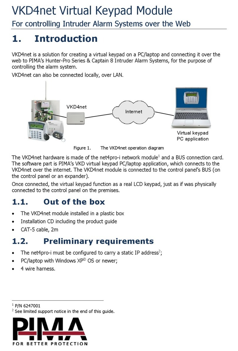
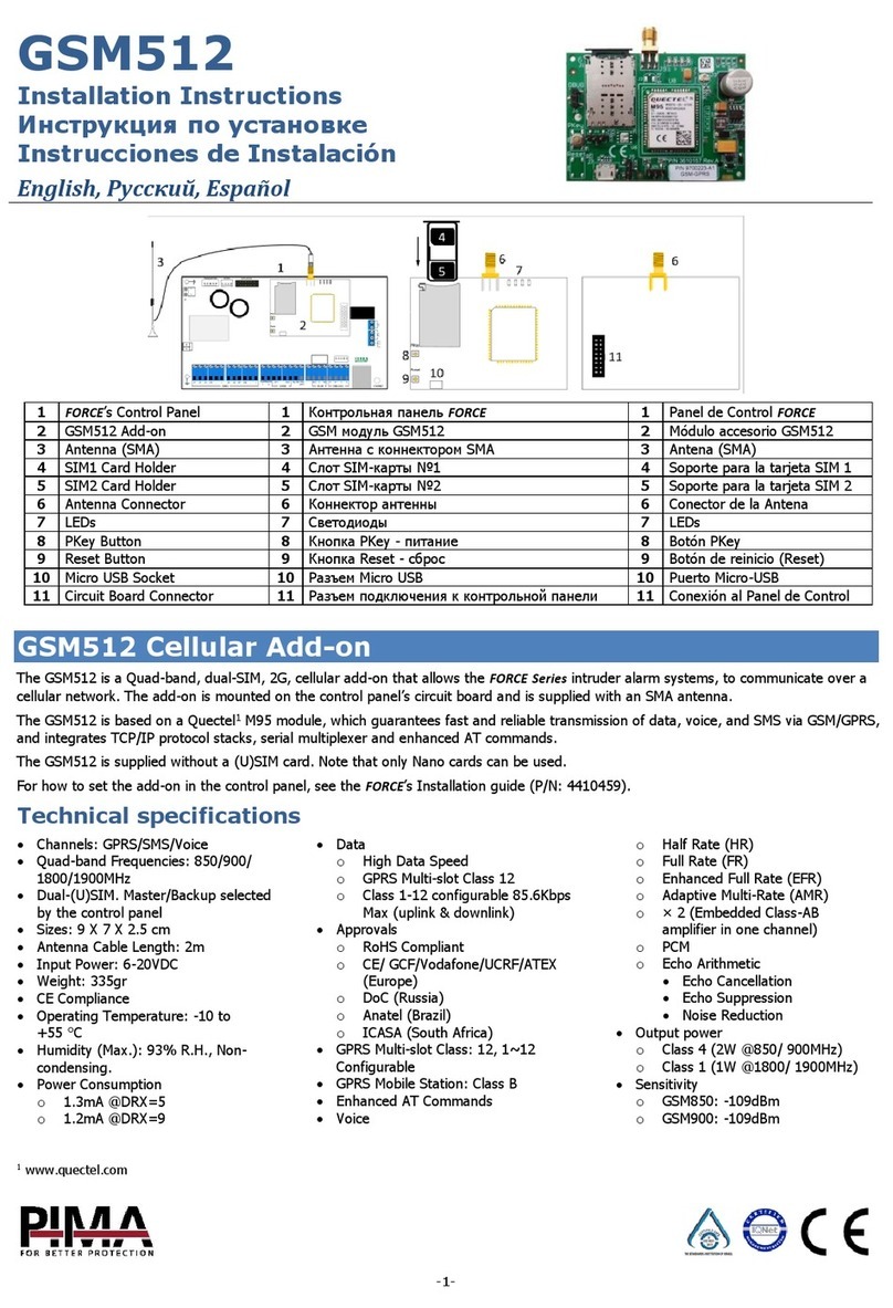
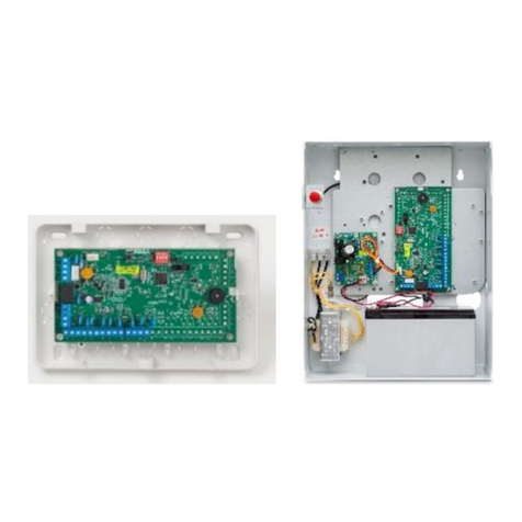
Pima MWA500 User manual

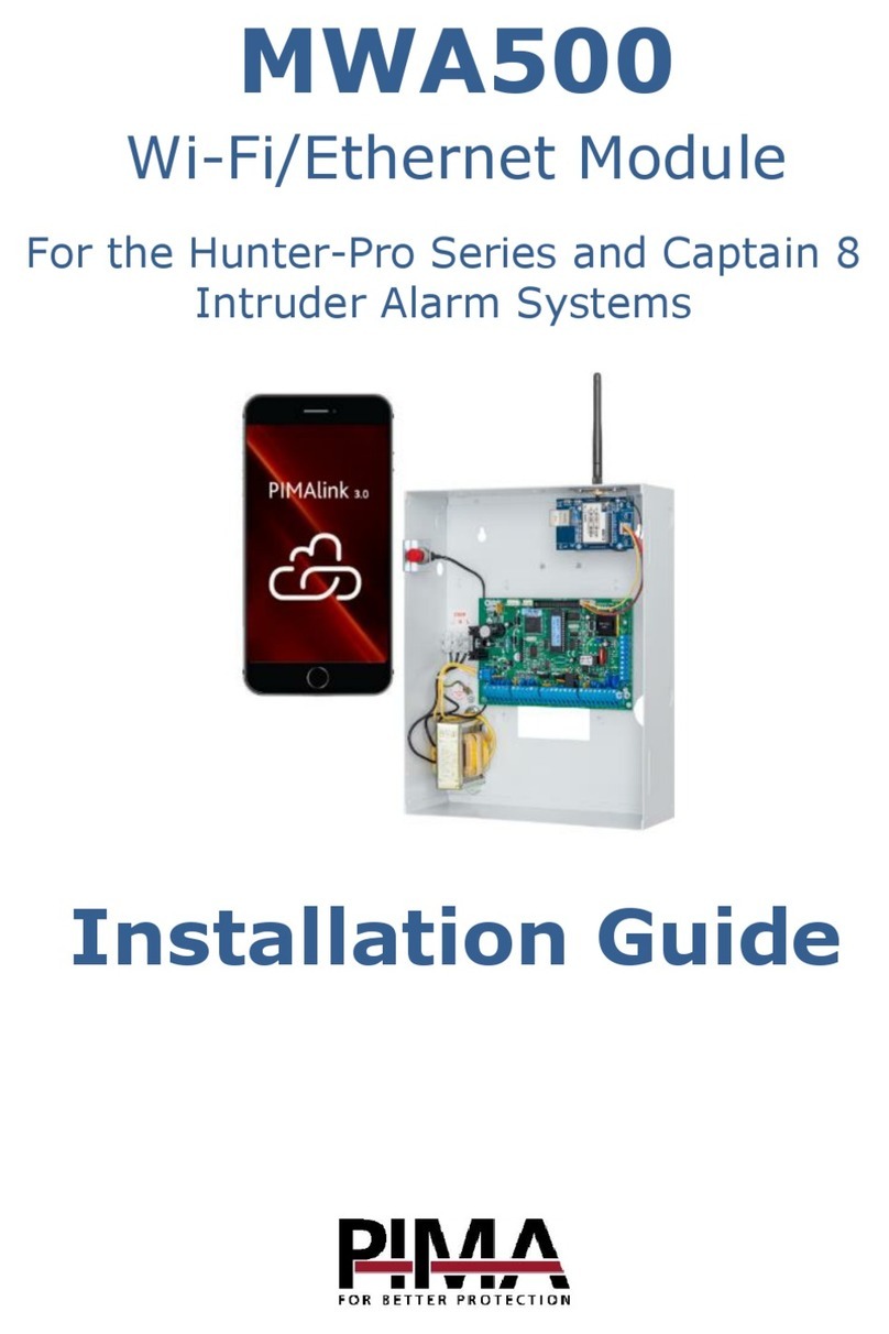
MWA500
Wi-Fi & Ethernet Communication Module
for the Hunter-Pro Series and Captain 8
Installation Guide
P I M A E l e c t ro n i c Sy s t e m s L t d .

MWA500 Wi-Fi & Ethernet Module Installation Guide
2
Table of contents
Introduction .................................................................................................................. 3
Features ............................................................................................................................. 3
Package contents of the product .......................................................................................... 3
Technical specifications ....................................................................................................... 3
Quick Reference Guide .................................................................................................. 4
Installation .................................................................................................................... 4
Configuration................................................................................................................. 5
How to connect to the MWA500........................................................................................... 5
How to change the
Account
(username) and
Password
.......................................................... 5
How to configure the module............................................................................................... 5
How to Reset the MWA500............................................................................................ 7
Limited Warranty
PIMA Electronic Systems Ltd. does not represent that its product may not be compromised and/or
circumvented, or that the Product will prevent any death, personal and/or bodily injury and/or damage to
property resulting from burglary, robbery, fire or otherwise, or that the Product will in all cases provide
adequate warning or protection. The User understands that a properlyinstalled and maintained equipment may
only reduce the risk of events such as burglary, robbery, and fire without warning, but it is not insurance or a
guarantee that such will not occur or that there will be no death, personal damage and/or damage to property
as a result.
Read this guide in its entirety before attempting to program or operate your system. Should you misunderstand
any part of this guide, please contact the supplier or installer of this system.
Copyright 2018 PIMA Electronic Systems Ltd. All rights reserved. E&OE

Introduction
3
Introduction
This guide will help you through the installation and configuration of the Hi-Link (www.hlktech.net)
MWA500 Wi-Fi & Ethernet communication module. The module lets users of the Hunter-Pro Series
and Captain 8 alarm systems, to use the iPima app.
The module is mounted inside the enclosure of the control panel and is configured using any
standard web browser.
Features
Wi-Fi connection in several standards
Ethernet connection to local (LAN) network
Mounted in the enclosure of the control panel
Easy browser configuration interface
Package contents of the product
MWA500 module, mounted on a bracket that fits to the enclosure of the control panel.
Antenna
2 screws
This guide
Technical specifications
Network Standard
Wireless: IEEE 802.11n, IEEE 802.11g, IEEE 802.11b
Ethernet: IEEE 802.3, IEEE 802.3u
Transmission Rate
11n: maximum up to 150Mbps
11g: maximum up to 54Mbps
11b: maximum up to 11Mbps
Frequency Range
2.4 - 2.4835GH
Interface
10/100Mbps, LAN/WAN, Multiplex
Antenna
External
Temperature
-10 to +50 OC
Humidity
90%, non-condensed

MWA500 Wi-Fi & Ethernet Module Installation Guide
4
Quick Reference Guide
Figure 1. The MWA500
Installation
Disconnect the control panel from AC and battery power prior to
installation.
Avoid touching the antenna’s wire connection.
1. Carefully pass the antenna through the hole in the top of the control panel’s enclosure, from
inside out.
If radio transmitter of GSM communicator are mounted before, break the right or
left knockouts and use them for the module.
2. Mount the module by fastening its bracket to the enclosure, using the supplied screws.
3. Connect the wire braid between the module and the SERIAL (J4) connector in the control panel.
4. Connect the control panel to power. The LEDs on the Wi-Fi module should lit.
Figure 2. Connection diagram
WAN
LAN
Exit/Default
WPS/Default
Power
LAN
Wi-Fi
To SERIAL
Connector
Power and
Network LED’s
Reset
Button
Ethernet
Connector Not in use
LED’s
MWA500
Control Panel
WAN
LAN
Exit/Default
WPS/Default
SERIAL
Connector

Configuration
5
Configuration
How to connect to the MWA500
First, you need to join the module to the local network (LAN). To do that, do the steps that follow:
1. Click the network connection icon on the desktop of the laptop.
2. In the network connection window, select
HI-LINK
and click
Connect
.
If
HI-LINK
is not on the connections list, make sure the module is up
and running.
3. Enter 12345678 in the password window to join the network.
4. Open a web browser, type the IP address of 192.168.16.254 and press
Enter
.
5. In the login window that opens up, enter
admin
as user name and as password, and click
Log in
. You must change these default definitions in the process of installation.
How to change the Account (username) and Password
The first time you login, you must change the default username and password of the module. To
do that, do as follows:
1. Click
Administration/Management
.
2. Under
Administrator Settings
, set new
Account
(username) and
Password
. Make sure to write
down the new definitions.
3. Click
Apply
.
How to configure the module
Serial2Net Settings
1. Click
Serial2Net Settings
on the left pane.
2. Use the next table to set the module’s parameters. When you are done,
press
Apply
to save and restart the module:

MWA500 Wi-Fi & Ethernet Module Installation Guide
6
No.
Parameter
Select/Type
1.
NetMode
WIFI(CLIENT)-SERIAL
for Wi-Fi mode
ETH-SERIAL
for Ethernet mode
2.
SSID (Wi-Fi mode only)
Press
Scan
and wait for the module to detect Wi-Fi networks.
When the list appears, select the desired one and click
Apply
.
3.
Encrypt Type
(Wi-Fi mode only)
See the network settings.
4.
Password
The password of the router
5.
IP Type
Select
STATIC
6.
IP Address
The LAN address of the module. Use this address for port
forwarding1. Make sure to write down the address, or you will
have to reset the module to login.
7.
Subnet Mask
See the network settings.
8.
Default Gateway
See the network settings.
9.
Primary DNS Server
See the network settings.
10.
Secondary DNS Server
Do not change.
11.
Serial Configure
2400,8,n,1
12.
Serial Framing Length
256
13.
Serial Framing Timeout
2000
14.
Network Mode
Select
Server
.
15.
Remote Server Domain/
IP
The IP address of the router
16.
Locale/Remote Port
Number
Set between 10150 and 10160.
17.
Network Protocol
Select
TCP
.
18.
Network Timeout
Do not change.
Advance Settings
Use the next table to set the module’s special settings. When you complete, press
Apply
to save
and restart the module:
No.
Parameter
Select/Type
1
TCP AUTO CONNECT
Enable
2
SERIAL ESCAPE
Disable
SERIAL ESCAPE2
SERIAL ESCAPE2 TIME
3
SERIAL ESCAPE2 TIME
2000
1
See limitation note at the last page.

How to Reset the MWA500
7
No.
Parameter
Select/Type
4
SERIAL FRAME
INTERVAL TIMEOUT
1500
5
Client Locale Port
Set the same as in
Locale/
Remote Port Number
above.
6
WIFI Channel
Select ‘1’
7
SERIAL RTS(GPIO_1)
Disable
SERIAL XON/XOFF
How to Reset the MWA500
To reset the module to its factory default settings, follow the next steps:
1. While the module is connected to power, press and hold the
Exit/Default
button for 10
seconds.
2. Wait 2 seconds.
3. Press again the
Exit/Default
and wait for the two green LEDs to extinguish. The module will
now reset itself.

MWA500 Wi-Fi & Ethernet Module Installation Guide
8
Limited support notice:
Due to the diverse mix of networks, we are not able to offer support on routers, modems,
switches or any other network/internet related devices or services.
Our support for internet or network related features, that are not directly related to the product
are limited.
The following must be completed before calling our support team with network/internet related
features:
1. Your network/internet must be configured and working
2. IP address and port number for the product must be pre- configured on the network
3. Also, have the following information available: default Gateway, Subnet mask, port
numbers and all other network information
PIMA Electronic Systems Ltd. WWW.PIMA-ALARMS.COM
5 Hatzoref Street, Holon 5885633, Israel
Tel: +972.3.6506414
Fax: +972.3.5500442
Email: support@pima-alarms.com
P/N: 4410456
*4410456*
Revision: A3, XX en, Mar 2018
Table of contents
Other Pima Control Unit manuals