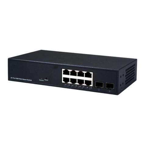
Next Network NEXT-POE4008L2-130 User manual

1
NEXT-POE4008L2-130
8 Port 10/100/1000Mbps PoE
and Gigabit combo SFPs/ RJ-45s
Web managed Switch
User’s Manual

2
CONTENTS
CONTENTS...........................................................................................................................................2
Revision History ..................................................................................................................................5
Safety Warning ...................................................................................................................................6
Chapter 1 Introduction............................................................................................................7
PRODUCT OVERVIEW......................................................................................................................7
FEATURES........................................................................................................................................7
SPECIFICATIONS..............................................................................................................................9
PERFORMANCES .............................................................................................................................9
PACKING .......................................................................................................................................10
Chapter 2 Hardware Descriptions .........................................................................................11
DIMENSION...................................................................................................................................11
AND WEIGHT ................................................................................................................................11
LED INDICATORS ...........................................................................................................................11
REAR PANEL ..................................................................................................................................12
HARDWARE...................................................................................................................................12
INSTALLATION...............................................................................................................................12
Chapter 3 Web Management ..........................................................................................14
Initial Switch .................................................................................................................................14
Configuration................................................................................................................................14
Front Panel....................................................................................................................................16
MENU TREE...................................................................................................................................17
System Information ......................................................................................................................23
IP & Time.......................................................................................................................................24
Log ................................................................................................................................................26

3
Power Reduction (LED).................................................................................................................27
Thermal Protection.......................................................................................................................29
Ports..............................................................................................................................................30
Security .........................................................................................................................................33
SNMP ............................................................................................................................................35
Network ........................................................................................................................................46
Port Trunking(Static).....................................................................................................................55
Port Trunking(LACP)......................................................................................................................56
Loop Protection ............................................................................................................................58
Spanning Tree...............................................................................................................................60
IGMP SNOOPING ..........................................................................................................................65
Power Over Ethernet....................................................................................................................68
IEEE 802.1Q VLAN.........................................................................................................................70
Quality of Service..........................................................................................................................78
SYSTEM .........................................................................................................................................89
INFORMATION..............................................................................................................................89
INFORMATION OF.......................................................................................................................119
SPANNING TREE..........................................................................................................................119
SHOW IGMP SNOOPING.............................................................................................................126
INFORMATION............................................................................................................................126
SHOW..........................................................................................................................................130
POWER OVER ETHERNET............................................................................................................130
DISPLAY INFORMATION..............................................................................................................132
OF VLANs ....................................................................................................................................132
Chapter 4 Web Maintenance Restart Device.................................................................139
RESTART DEVICE .........................................................................................................................139
FACTORY DEFAULTS....................................................................................................................139

4
SOFTWARE UPLOAD ...................................................................................................................140
SWAP IMAGE ..............................................................................................................................141
SAVE CONFIGURATION...............................................................................................................144
UPLOAD CONFIGURATION..........................................................................................................145

5
Revision History
Version
Date
Author
Changes from Previous Version
1.0
April 28, 2015
Mori/Jes
Released

6
Safety Warning
Purpose
This manual gives specific information on how to operate and use the
management functions of this switch.
Audience
This manual is intended for use by network administrators who ar e
r
espo ns i ble for operating and maintaining networ k equi pme nts
;
consequently, it assumes a basic network network knowledge of general
switch functions, the Internet Protocol (IP), IEEE 802.3at/af Power over
Ethernet Standard and Simple Network Management Protocol(SNMP).
FCC Warning
This device has been tested and found to comply with limits for a Class A
digital device, pursuant to Part 15 of FCC Rules. These limits are designed
to provide reasonable protection against harmful interference when the
equipment is operated in a commercial environment. This equipment
generates and radiates radio frequency energy and, if not installed and
used in accordance with the user’s manual, it may cause interference in
which case users will be required to correct interference at their own
expenses.
CE Warning
This is a Class A product. In a domestic environment, this product may
cause radio interference in which case the user may be required to take
adequate measures.

7
Chapter 1 Introduction
This chapter provides an overview of this PoE Web Smart
switch, and introduces the key features and supported
specifications of this PoE Web Smart switches.
PRODUCT OVERVIEW
This PoE switch is a PoE L2+ Managed switch equiped with
8-ports 10/100/1000BaseT(X) plus 2-ports gigabit SFP
open slots. It provides a broad range of features for Layer
2+ switching and fully 802.3at/af PoE/PoE+ functions.
It was designed for easy installation and high
performance in an environment where the traffic is on
the network and the number of users increases
continuously. The smart and efficient power design can
improve the power saving.
FEATURES
Features
Descriptions
Dual Images
Prevent any kind of upgrading process
failure
IPv4
Supports IPv4 addressing,
management and QoS
Log
Support local and remote syslog server
with 3 levels(Info, Warning, Error)
Power Saving
ActiPHY, PerfectReach
LED Power management
Thermal Protection
Security
Private VLAN(Static)
ACLs for filtering, policing, and port
copy, including ACL wizards

8
(continued)
Authentication
Telnet, Web - username/password
Telnet - SSH
SNMP v1/2c –Community strings
SNMP version 3 –MD5 or SHA
password
Port-based 802.1X
Port Limiting
Input rate limiting per port(manual
setting or ACL)
Port Configuration
Speed, Duplex mode, Flow control,
MTU, Power saving mode
Port Mirroring
1 sessions, up to 10 source port to
one analysis port per session
Port Trunking
IEEE 802.3ad Link Aggregation, static
and LACP
Spanning Tree
Algorithm
Supports standard STP, Rapid
Spanning Tree Protocol (RSTP)
IEEE 802.1D Bridge
Supports dynamic data switching and
addresses learning
Quality of Service
Traffic classes(1,2, or 4/8 active
priorities)
Storm control for UC, MC and BC
DHCP
Client
Configuration
Save and Restore configuration
Firmware
Upgrade & firmware image switch
using Web & console port
CLI command
Support Cli command with console
port (Baudrate:115200, DataBit:8,
Parity: N,StopBit 1)

9
SPECIFICATIONS
Standard
IEEE 802.3at/af Power over Ethernet(PoE/PoE+)
IEEE 802.3ad Link Aggregation
IEEE 802.3x Flow Control
IEEE 802.1x Port-based Network Access Control
IEEE 802.1Q VLAN Tagging
IEEE 802.1d Spanning Tree Protocol
IEEE 802.1w Rapid Spanning Tree Protocol
8 integrated IEEE 802.3ab-compliant 10/100/1000BASE-T
Ethernet
MIBs
RFC 1213 MIB II
RFC 3411 SNMP Management Frameworks
RFC 3621 LLEP-MED Power
RFC 3635 Ethernet-like MIB
RFC 4188 Bridge MIB
IEEE 802.1AB LLDP MIB
PERFORMANCES
Information
MAC Address : 8K , 4K VLAN support
Packet Memory : 4 Megabits of Integrated shared memory
Jambo Frame : 9.6K
Transmission Method : Store and Forward

10
PACKING
Before you start to install this switch, please verify your package that
contains the following items:
One PoE 8+2-port Gigabit Ethernet Switch
One Power Cord
One User’s Manual (CD disk)
Note: If any of these items is found missing or damaged, please
contact your local supplier for replacement.

11
Chapter 2 Hardware Descriptions
This chapter primarily presents hardware of the PoE
switch,
physical dimenstions and functional overview would be
described.
DIMENSION
AND WEIGHT
263 x 160 x 44 mm (H x W x D) / 1.5kg
FRONT PANEL
The Front Panel of the PoE L2+ managed switch consists of
8-port gigabit ethernet port and 2-port gigabit SFP open
slot. The LED indicators are also located on the Front
Panel.
LED INDICATORS
The LED Indicators present real-time information of
systematic operation status. The following table provides
the description of LED status and meanings.
LED
Status
Description
Power
Orange
System on
Nil
System off
PoE
Orange
Port is linked to Power Device
Nil
No Power Device is connected
Link/ACT
Green and
Flashing
Link and Data Activating
Nil
Port is disable or disconnected

12
REAR PANEL
The 3-pronged power plug is placed at the rear panel of the
PoE Web Smart Switch right side show as below:
HARDWARE
INSTALLATION
Installing Equipment
You can mount the this device into a standard 19-inch
equipment rack. You can center- or front-mount the device
in a rack. Optional rack-mounting brackets are supplied with
the device.
Connecting Networking

13
Connecting Power
The AC power cord shipped with the device connects the
device to earth ground when plugged into an AC
grounding-type power outlet. The device must be connected
to earth ground during normal operation. To connect power
to the device, plug one end of the AC power cord into the AC
power appliance inlet on the back panel of the device. Plug
the other end into an AC power source.
Power ON/OFF Device
To power on this device, press the AC power switch on the
rear panel to the on position. The POWER LED lights during
startup and remains on steadily when the device is operating
normally. To power off this device, press the power switch to
the OFF position.

14
Chapter 3 Web Management
This chapter provides the entire L2+ managed switch
features, along with a detailed description of how to
configure each feature via web interface.
Initial Switch
Configuration
This part guides you to configure and manage this switch
through the web interface. With this facility, you can
easily configure and monitor through any one port of this
switch.
Start up by the following steps:
1. Place the switch close to your PC/NB that you intend
to use for configuration. It will help you to check the
status of the switch by LED in front panel while
working on your PC/NB.
2. Connect the Ethernet port of your PC/NB to any port
on the front panel of the switch. Turn the switch on
and make sure the connectivity by checking LED in the
front panel of the switch.
3. Configure your PC’s IP address the same subnet with
the switch’s.
The following table describes the default necessary
login Information:
Login Information
IP Address
192.168.2.1
IP Mask
255.255.255.0
IP Router
0.0.0.0
Username
admin
Password
4. Open the web browser, and go to 192.168.2.1Site then
the login windows will pop out. Key in the username
“admin” and leave password blank then clicks OK.

15
Figure 3-1.
5. After you login successfully, you will see the home
page is displayed as shown below. The home page
display the Menu Bar on the left side of the screen
and show the front panel port states on the right side.
Before you start to configure, we strongly recommended
you to change the password. To change the password,
click Security and then Switch. Fill old and new password
in Password tab.
WEB Interface
Configuration Option Configurable parameters have
seveal forms : text field, drop-down list, radio button and
checkbox. Once you change the parameters, please make
sure to click Save button to apply

16
The following table provides the description of each
button:
Configuration buttons
Front Panel
The default page after you login successfully is port states’
page. The port 1 to port 8 are gigabit Ethernet port and
port 9 and 10 are SFP slot. When the port image is green,
it means this port is connected. Auto-refresh mode is
disable by default setting. It will update the current port
state by 5 seconds if you check it. Or you can click Refresh
button to update the states manually. Click the each
port image will open detailed statstics of selected port.
Button
Description
Save
Set specific value into the Switch
Reset
Restore the parameters to previous saving
value
Show the help information for selected
page
Logout the management web interface of
the switch

17
MENU TREE
There is a Menu Tree in the left side of Web management
system with 4 categories: Configuration, Monitor,
Diagnostic and Maintenance. The follow table has a
breifly description of each tab.
MENU TREE
Menu
Descriptions
Configuration
System
Information
Configures system contact,
name, location and timezone
offset
IP & Time
Configures IPv4 (Statics IP
Address, DHCP client), VLAN ID
and SNTP settings
Log
Configures Remote system log
Server which 3 levels( Infor,
Warning, Error)
Power Reductinon
LED
Reduces LED intensity during
specified hours and configure
link change at error settings
Thermal Protection
Configures temperature 4
priority levels and each value.
Port will shut-down if the
temperature exceeded the
assigned value.
Ports
Configures ports’ connection
settings
Secuirty
Switch
Password
Change the new password
Auth Method
Configures authentication
method for console and web
access via local database and
RADIUS

18
Table. MENU TREE (Continue)
Menu
Descriptions
SNMP
System
Configures read-only and R/W
community strings for SNMP
v1/v2c, engine ID for SNMP v3,
and trap parameters
Communities
Configures community strings
Users
Configures SNMP v3 users on this
switch
Groups
Configures SNMP v3 groups
Views
Configures SNMP v3 views
Access
Assigns security model, Security
level, and R/W views to SNMP
groups
Network
ACL
Access Control Lists
AAA
Configures RADIUS authentication
server.( Max 5 Server supported)
Port Trunking
Static
Speifies ports to group into static
trunks
LACP
Allows ports to join trunk
dynamically
Loop Protection
Configure ports to shutdown if the
ports are in loop
Spanning Tree
Bridge Setting
1. Configures global bridge
setting for STP and RSTP
2. Configures edge port setting
for BPDU filtering, BPDU guard
and port error recovery

19
MENU TREE (Continue)
Menu
Descriptions
Bridge Ports
Configure CIST port, priority and
path cost
IPMC
IGMP Snooping
Basic
Configuration
Configures global and related
port setting
VLAN
Configuration
Configures IGMP snooping per
VLAN group
PoE
Configures total power supply
and each PoE port
type(PoE/PoE++/disabled)
VLANs
VLAN
Membership
Configures VLAN groups
Ports
Specifies default PVID and VLAN
atrributes
Private VLANs
PVLAN
Membership
Configures PVLAN groups
Port isolation
Configures Port isolation
QoS
Port Classification
Configures QoS Ingress
Classification Settings for all
ports
Port Policing
Configures QoS ingress Port
policers to constrain traffic flows
and mark frames by specific rate
QoS Control List
Configures QoS Control Entry based
on parameters such as VLAN ID,
UDP/TCP port, IPv4 DSCP or Tag
Priority
Storn Control
Set limitation for broadcast,
unicast and multicast traffic

20
MENU TREE (Continue)
Menu
Descriptions
Mirroring
Set source and destination port
for mirroring
Monitor
System
Information
Displays system contact, name,
location, switch’s MAC address,
system time, firmware version
CPU load
Displays CPU load by realtime
SVG graph
Log
Displays logged message with
selected level (Info, Warning,
Error, All)
Detailed Log
Displays fully logged message
Thermal Protection
Shows the current port
temperature and status
Ports
State
Displays a graphic image of the
front panel to indicate current
port states
Traffic Overview
Shows the basic port statistics
QoS Statistics
Shows the count of incoming
and outgoing egress queues
QCL Status
Shows the QoS Control Lists
status
Detailed Statistics
Shows the detailed port
statistics
Security
Network
ACL Status
Shows the ACL status by
different ACL users
Table of contents
Other Next Network Switch manuals
Popular Switch manuals by other brands

H3C
H3C S5130S Series Compliance and Safety Manual

Rose electronics
Rose electronics KVM-4THD/4K Installation and operation manual
NexxTech
NexxTech 1518896 manual
NETGEAR
NETGEAR Nighthawk SX10 Pro Gaming user manual
Panasonic
Panasonic GA-AS48TPoE+ Series installation guide
IMC Networks
IMC Networks iMcV-Switch Operation manual
