Next PROAUDIO LA26 User manual

LA26 / LAs15(A)
USER MANUAL
v202003
Thank you for purchasing NEXT-proaudio Speakers and their associated products.
Please carefully follow the instructions in this manual to ensure long, trouble-free use of your equipment.

INTRODUCTION
INTRODUCTION -1-
UNPACKING -1-
LA SERIES OVERVIEW -1-
SAFETY FIRST
SAFETY FIRST -2-
ACCESSORIES
LA26/LAS15(A) ACCESSORIES 4
PERFORMANCE
ELECTRO-ACOUSTICAL PERFORMANCE -6-
SYSTEM
LA26/LAS15/LAS15A CONNECTORS -7-
PASSIVE SYSTEM -7-
EXTENDING RANGE WITH PASSIVE SUBWOOFER -8-
HYBRID SYSTEM -8-
AMPLIFIER
DPA4000 POWER AMPLIFIER -9-
LAS15A PRESET LIST -9-
SOFTWARE
LAS15A TO PC CONNECTION -10-
SOUNDWARE 4.0 -10-
RIGGING/TRANSPORT
LA26 RIGGING SYSTEM -11-
LAS15/LAS15A RIGGING SYSTEM -11-
FLYING FRAME FOR LA26 -11-
FLYING ADAPTER BETWEEN LA26 AND LAS15(A) -11-
GROUND STACK SUB ADAPTER FOR LA26 11
GROUND STACK ACCESSORY -12-
U-SHAPE BRACKET FOR LA26 -12-
FLIGHT-CASE FOR LA26 12
INDIVIDUAL DOLLY FOR LAS15(A) 12
www.next-proaudio.com
CONTENTS

www.next-proaudio.com
CONTENTS
MECHANICAL LIMITS
MACHINERY DIRECTIVE 13
FLOWN CONFIGURATIONS 13
STACKED CONFIGURATIONS 13
RIGGING PROCEDURES
ASSEMBLY - LA26 | FLYING FRAME FOR LA26 14
ASSEMBLY - LAS15(A) | FLYING FRAME FOR LA26 15
ASSEMBLY - LAS15(A) | LA26 | FLYING ADAPTER BETWEEN LA26 AND LAS15(A) 16
ASSEMBLY - LAS15(A) | LA26 | U-SHAPE BRACKET FOR LA26 17
STACKING PROCEDURES
ASSEMBLY - LAS15(A) | DOLLY 18
ASSEMBLY - LA26 | LAS15(A) | GROUND STACK SUB ADAPTER FOR LA26 19
ASSEMBLY - LA26 | FLYING FRAME 20
COMPLETE SYSTEM EXAMPLES
EXAMPLE 1 21
EXAMPLE 2 21
EXAMPLE 3 21
SERVICE
TROUBLESHOOTING 22
WARRANTY POLICY 22
END-OF-LIFE 22
TECHNICAL
LA26 TECHNICAL SPECIFICATIONS 23
LA26 DIMENSIONS 23
LAS15 TECHNICAL SPECIFICATIONS 24
LAS15 DIMENSIONS 24
LAS15A TECHNICAL SPECIFICATIONS 25
LAS15 DIMENSIONS 25
REACH US
CONTACTS 26

1www.next-proaudio.com
INTRODUCTION
INTRODUCTION
Thank you for purchasing a NEXT LA26/LAs15(A) Line Array element. This manual will provide you with
useful and important information about your NEXT LA26/LAs15(A) element. Please devote some time reading
this manual, and keep it at hand for future reference. NEXT-proaudio is concerned with your safety and well-be-
ing, so please follow all instructions and heed all warnings. Also, a better understanding of some specic
features of the LA26/LAs15(A) line array element will help you to operate your system to its full potential. With
a continuous evolution of techniques and standards, NEXT-proaudio, reserves the right to change the speci-
cations of its products without early warning. For the most current data, please visit our website:
www.next-proaudio.com
UNPACKING
Each NEXT LA26/LAs15(A) line array element is built in Europe (Portugal) by NEXT-proaudio, to the highest
standard and thoroughly inspected before it leaves the factory. When unpacking the NEXT LA26/LAs15(A),
examine it carefully for any signs of possible transit damage and inform your dealer immediately if any such
damage is found.
It is suggested that you retain the original packaging so that the system can be repacked in the future if
necessary. Please note that NEXT-proaudio and its authorized distributors cannot accept any responsibility for
damage to any returned product through the use of non-approved packaging.
LA SERIES OVERVIEW
The LA26, LAs15 and LAs15A are part of the NEXT-proaudio LA series. LA26 it’s an ultra-compact line array
element that incorporates an impressive battery of high technology features that makes it able to achieve an
unprecedented level of performance on compact line array systems.
The LA26 houses two 6.5" neodymium Planar Diaphragm drivers located in the side walls of the HF Oblate
Spheroidal Waveguide, a 2" diaphragm HF neodymium driver and a passive network crossover presenting a
nominal input impedance of 16.
The LF Planar Diaphragm drivers, and its special placement, integrated on the Spheroidal Waveguide,
reduces the cavity eect, associated with traditional cone speakers, radiating sound energy smooth and evenly
over the entire coverage area. This special arrangement perfectly combines the HF and LF acoustic centres to
generate precisely coherent wave fronts uniformly spread in the horizontal plane and precisely coupled in the
vertical plane.
The LA26 was designed to be incredibly versatile solving the needs of production companies, rental
houses, theatres, houses of worship, working as main system, front ll, side array or as complement of
larger-scale LA systems.
For low frequency extension LAs15 or LAs15A, active subwoofer, can be used. The LAs15A is capable to
process and power up to three LA26 passive line array elements.

SAFETY FIRST
• Try not to operate the LA26 or LAs15(A) under heavy rain or moisture.
• Do not expose the systems to extreme heat or cold conditions to prevent component damage.
• Never place your speaker in a way that prevents air ow near to the side bass reex ports. A minimum clear-
ance distance of 10cm should be kept between the ports and any near surface.
• Place cables in a way that they do not present a trip hazard.
• Do not place any objects on top of the speaker, they can fall accidentally and cause injuries.
• Do not attempt to move the speaker while connected.
• Do not attempt to service the speaker beyond what is described in this manual. All other service or repair of
this product should be carried only by qualied personnel.
• To prevent electric shock, do not use any extension cord, receptacle or other outlets where the blades of the
connectors cannot be fully inserted.
• Do not operate the unit for an extended period of time with the sound distorting.
• When connecting several speakers, make sure that all the speakers have the same polarity and that the ampli-
er is not overloaded.
• Always ensure that the oor or structure where the stack will be placed is even and can withstand the weight
of the complete stack.
• Do not stack speakers too high, especially outdoors where winds could topple the stack.
RIGGING AND SUSPENSION SAFETY CONSIDERATIONS
• Before rigging or suspending NEXT LA26/LAs15(A) systems, inspect all components and all hardware for any
signs of damage or missing parts.
• If you nd any damaged, corroded or deformed parts, do not use them, replace them immediately.
• Do not use any hardware with a safety factor lower than 4. Don’t forget that the hardware won’t just hold the
systems weight, it has to be sturdy enough to handle dynamic forces like winds with no deformation.
• NEXT LA26/LAs15(A) system installation should only be carried out by qualied personnel.
• Always use adequate protective clothing and equipment to prevent possible injuries.
• Be sure you understand all local and national regulations regarding equipment installation.
• NEXT-proaudio is not responsible for any rigging equipment or accessories provided by third party manufac-
turers. Ensure that the Working Load Limit (WLL) of the whole rigging parts is respected.
• Failure to comply with these instructions may result on injury or death.
2
www.next-proaudio.com
SAFETY FIRST

SAFETY FIRST
3
SAFETY FIRST
www.next-proaudio.com
CAUTION
RISK OF ELECTRIC SHOCK
DO NOT OPEN
TO REDUCE THE RISK OF ELECTRIC SHOCK, DO NOT REMOVE COVER
NO USER SERVICEABLE PARTS INSIDE
REFER SERVICE TO QUALIFIED PERSONNEL
LA Series systems are capable of producing extremely high sound pressure levels and
should be used with care. Hearing loss is cumula�ve and can result from levels above
90dB if people are exposed for a long period. Never stand close to loudspeakers
driven at high levels.
DANGER - HEARING DAMAGE
CAUTION
HIGH SPL

4
www.next-proaudio.com
ACCESSORIES
LA26/LAs15(A) ACCESSORIES
Flying Frame for
LA26/LAs15(A) NC18207
NC66207
NC67207
NC18207
Dimensions Descrip�on Reference
Flying Adapter
between
LA26 and LAs15(A)
Ground Stack Sub
Adapter for LA26
U-Shape Bracket
for LA26
479
533
100
213
580
524
470
126
125
456
30
153
63
503
511
576
554
185
128
90°
15°
0º

5
ACCESSORIES
www.next-proaudio.com
NC65207
Dimensions Descrip�on Reference
LAs15(A) Dolly NC75216
VP60057
VP60053
Rigging Shackle
Ground Stack
Accessory
8mm/10mm
Lock Pin
590
509
146
170

ELECTRO-ACOUSTICAL PERFORMANCE
Sensitivity curve of a single LA26 cabinet (Full-Range Operation) using NEXT-proaudio’s audio processing.
The measurement was made in anechoic environment at 1W@1m.
NEXT-proaudio’s LA26 has a nominal horizontal coverage of 100º and 12º on the vertical axis. The yellow region
represents the -6dB.
6
www.next-proaudio.com
PERFORMANCE
Frequency (Hz)
10k5k2k1k5002001005020 20kHz
110
dBSPL
100
90
80
70
60
Frequency Response
Horizontal Directivity Analysis

SYSTEM 4 x 2
N-RAK 6
1 to 2
A(4xLA26)
CH1 - 1xLAs15
CH2 - 1xLAs15
CH3 - 2xLA26
CH4 - 2xLA26
AMP 1
CH1 - 1xLAs15
CH2 - 1xLAs15
CH3 - 3xLA26
CH4 - 3xLA26
AMP 1
CH1 - 1xLAs15
CH2 - 1xLAs15
CH3 - 2xLA26
CH4 - 1xLA26
AMP 1
CH1 - 1xLAs15
CH2 - NC
CH3 - 3xLA26
CH4 - 3xLA26
AMP 2
CH1 - 1xLAs15
CH2 - 1xLAs15
CH3 - 3xLA26
CH4 - 3xLA26
AMP 1
CH1 - 1xLAs15
CH2 - 1xLAs15
CH3 - 3xLA26
CH4 - 3xLA26
AMP 2
A(6xLA26) A(3xLA26)
B(6xLA26)
A(6xLA26)
B(6xLA26)
1 to 2 1 to 3 1 to 4
N-RAK 6 N-RAK 12 N-RAK 12
6 x 2 9 x 3 12 x 4
N-RAK MODEL
N-RAK SUB OUT
N-RAK ARRAY OUT
AMPLIFIER
CHANNEL
DISTRIBUTION
7
SYSTEM
www.next-proaudio.com
LA26 / LAs15 / LAs15A CONNECTORS
All the speakON NL4 are connected to 1+ 1-. The other pins are not connected.
The LA26 has two NL4 internally linked.
The LAs15A has one XLR signal input, one XLR signal output and a NL4 connector to power up to 3 LA26.
PASSIVE SYSTEM
The passive systems must use NEXT-proaudio’s N-RAK. The recommended models are N-RAK 6 or N-RAK12
depending on the system’ size.
LA26 LAs15 LAs15A

EXTENDING RANGE WITH PASSIVE SUBWOOFER
The passive system’s frequency range can be extended to lower frequencies adding a LAs418 (2x4ohm).
In that case, the LAs15’s High-Pass Filter must be changed to 60Hz - 24dB/oct Linkwitz-Riley.
Connect the LAs418 (2x4ohm) using a NL4 connector with 4 conductors cable.
Match the Low-Pass Filter of the LAs418 with the LAs15’s High-Pass Filter.
Any of the N-RAK models can be used to power the extending range subwoofers.
HYBRID SYSTEM
The hybrid consists on Active subwoofers (LAs15A) powering the passive LA26. Each LAs15A is capable of
power up to 3 x LA26 cabinets. For increased headroom use 1:2 sub to top ratio.
8
www.next-proaudio.com
SYSTEM
# LAs418(2x4ohm) 2
N-RAK 6
1 and 5
CH1 - LAs418(1) LF1
CH2 - LAs418(1) LF2
CH3 - LAs418(2) LF1
CH4 - LAs418(2) LF2
AMP 1
CH1 - LAs418(1) LF1
CH2 - LAs418(1) LF2
CH3 - LAs418(2) LF1
CH4 - LAs418(2) LF2
AMP 1
CH1 - LAs418(3) LF1
CH2 - LAs418(3) LF2
CH3 - LAs418(4) LF1
CH4 - LAs418(4) LF2
AMP 2
CH1 - LAs418(1)
CH2 - LAs418(2)
CH3 - LAs418(3)
CH4 - LAs418(4)
AMP 1
CH1 - LAs418(1)
CH2 - LAs418(2)
CH3 - LAs418(3)
CH4 - LAs418(4)
AMP 1
CH1 - LAs418(5)
CH2 - LAs418(6)
CH3 - LAs418(7)
CH4 - LAs418(8)
AMP 2
1, 5, 3, 7 1 to 4 1 to 8
N-RAK 12 N-RAK 40 N-RAK 80
4 4 8
N-RAK MODEL
N-RAK SUB OUT
AMPLIFIER
CHANNEL
DISTRIBUTION
POWER UP TO 3xLA26

9
AMPLIFIER
www.next-proaudio.com
DPA4000 POWER AMPLIFIER
The heart of the LAs15A is a powerful, light weight, highly ecient Class D
power amplier module (2x2000W), with PFC switched mode power
supply, that delivers an impressive sonic punch with perfectly balanced,
rich and transparent sound at any volume. The integrated Networkable
DSP 24bit/96kHz provides 8 selectable memories (7 factory dened and 1
user dened) that can be accessed by an easy selector, located on the
module front panel or real time edited by a PC, using the supplied SOUND-
WARE software, via USB/RS485 remote control. This allows to easily
customize the sound program, for various applications.
With the SOUNDWARE software it is possible to edit each one of the 7
pre-loaded congurations and store it in the free memory. Editable
parameters are for example: input equalization, input delay, input
High-pass and Low-pass lters, Subwoofer Level/Delay/Polarity, Satellite
Level/Delay/Polarity. A total of 255 units can be controlled simultaneously
by the software.
AMPLIFIER LAYOUT:
1 - Signal Input/Output
2 - Level Adjustment Potentiometer
3 - Preset Selector
4 - RS485 Communication Interface
5 - USB Communication Interface
6 - List of Available Presets
7 - AC Mains Power Input/Output
8 - Protection Circuit Breaker
9 - Power On/O Switch
LAs15A PRESET LIST
0 - 1 LAs15A + 2 LA26-Pole: Flat Response for 1 Sub + 2 Tops mounted on a U-Bracket (connected to
the sub using pole mount).
1- 2 LAs15A + 4 LA26-Stack: Flat Response for 2 Subs + 4 Tops stacked
2- 2 LAs15A + 4 LA26: Flat Array response for small size arrays. 2 Subs + 4 Tops Flown.
3- 3 LAs15A + 6 LA26-Line: Flat Array response for medium size arrays. 3 Subs + 6 Tops Flown in line
or with small curvature.
4- 3 LAs15A + 6 LA26-Curv.: Flat Array response for medium size arrays. 3 Subs + 6 Tops Flown with
medium to large curvature.
5- = Preset 3 LAs15A Card.: This preset must be used on the same conditions as the preset 3 when a
cardioid subwoofer arrangement is needed. This preset must be active on the reversed sub
(NEXT-proaudio advises to reverse the middle one).
6- = Preset 4 LAs15A Card.: This preset must be used on the same conditions as the preset 4 when a
cardioid subwoofer arrangement is needed. This preset must be active on the reversed sub
(NEXT-proaudio advises to reverse the middle one).
7- User Dened: Free memory for user storage (Other presets are available online for download.
Load the .sdat preset into this free memory.
1
2
3
45
6
7
98
Never operate the LAs15A in a way
that maintains the Limiter Led
consistently on.
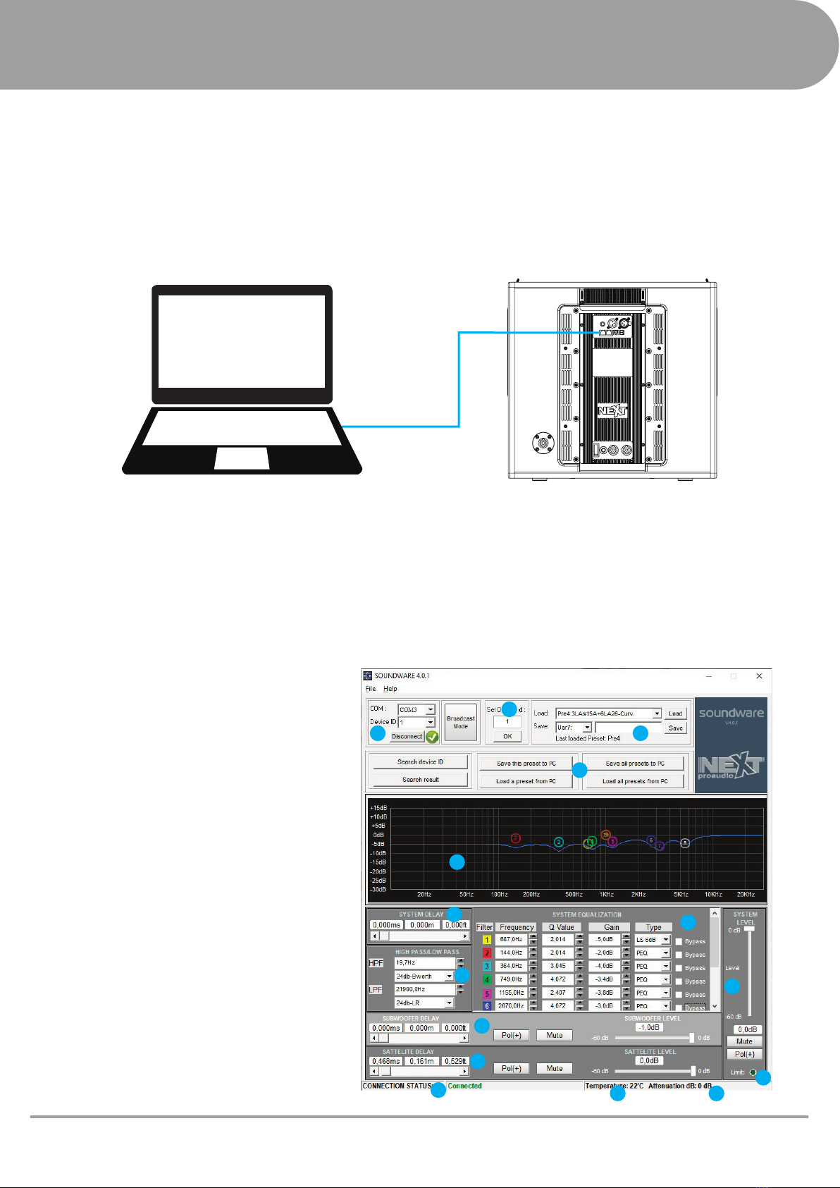
LAs15A to PC Connection
LAs15A can be connected to a PC using a RS485-USB or USB-USB cable. It is possible to connect up to 255
Devices in a single network. Download and install SOUNDWARE 4.0 (http://next-proaudio.com/downloads) on
the laptop, connect the laptop to the suboofer and launch the software.
SOUNDWARE 4.0
The soundware 4.0 is the supplied software to control and adjust the LAs15A.
10
www.next-proaudio.com
SOFTWARE
SOFTWARE LAYOUT:
1 - Connection Panel
2 - Device ID Panel
3 - Preset Selection Panel
4 - Import/Export Presets
5 - PEQ Graphics
6 - System Equalization (SUB+TOP)
7 - System Delay (SUB+TOP)
8 - System HPF/LPF (SUB+TOP)
9 - System Level/Polarity (SUB+TOP)
10 - LAs15A Delay/Level/Polarity
11 - LA26 Delay/Level/Polarity
12 - Connection Status
13 - LAs15A Internal Temperature
14 - System Attenuation in case of High
Temperature
15 - Limiter LED
1
2
3
4
5
6
7
10
12
11
13 14
15
9
8

11
RIGGING/TRANSPORT
www.next-proaudio.com
LA26 Rigging System
LA26 features a three-point rigging system composed of a rigging
swivel arm at the back and a pair of rigid rigging hardware at the front
sides. The inter-cabinet connection is ensured by tting the “male”
parts (blue circles) of the hardware into the next cabinet’s “female”
parts (yellow circles). There are two screws at the speaker’s sides to
attach a U-Bracket (pink circles).
LAs15/LAs15A Rigging System
LAs15/LAs15A features a four-point rigging system composed of two
pairs of rigging sliding arms, two at the back sides and a pair at the
front sides. The inter-cabinet connection is ensured by tting the
“male” parts (blue circles) of the hardware into the next cabinet’s
“female” parts (yellow circles).
Flying Frame for LA26
The ying frame is the device that allows to rig LA26 or LAs15/LAs15A.
It is compatible with both 3-point and 4-point rigging systems. The
frame has two sliding rigging shackles at the central bar and two
safety schakles. This device can also stack LA26, using the ground
stack accessory, or LAs15/LAs15A using the four swivel arms (yellow
circles). It is also possible to attach a LAP-TEQ clinometer (green circle).
Weight: 18.2kg
Flying Adapter between LA26 and LAs15(A)
The ying adapter is the device that allows to rig LA26 right after a
LAs15/LAs15A without any further hardware. It results in a clean visual
for the system seen from the front. This device has two connection
points, at the sides, to connect to the LAs15/LAs15A rear rigging
points (yellow circles). At the center, there are two rigging points
where the LA26 swivel arm will t (blue circles).
Ground Stack Sub Adapter for LA26
The ground stack sub adapter is the device that allows to stack LA26
right on top of a LAs15/LAs15A without any further hardware. It results
in a clean visual for the system. This device has two connection points,
at the sides, to connect to the LAs15/LAs15A rear rigging points (blue
circles). At the center, there are four stacking points (0º, 2º, 4º, 6º)
where the LA26 rigging hardware will t (yellow circle).
Front Rigging Point LAs15(A) Rear Rigging
Point
LA26 Rear Rigging
Point

12
www.next-proaudio.com
RIGGING/TRANSPORT
Ground Stack Accessory
The ground stack accessory is the device that allows to stack LA26
directly into the Flying Frame for LA26. There are two linking points at
the bottom that will connect to the frame (blue circles). At the top,
there are seven stacking points (-6º, -4º, -2º, 0º, 2º, 4º, 6º) where the
LA26 rigging hardware will t (yellow circles).
U-Shape Bracket for LA26
The U-Bracket can be used to secure up to three LA26 under a ceiling,
a balcony or structure. Using the pole-mount adapter, the U-Shape
Bracket can be used on a 35mm speaker pole. A maximum of two
LA26 can be pole-mounted on a LAs15/LAs15A.
NEVER ATTACH IT TO A WALL!
Flight-case for LA26
There are several types of ight-case congurations to easily transport
the LA26 cabinets.
- Flight-case for 3 x LA26 + Flying Frame
- Flight-case for 4 x LA26 + Flying Frame
- Flight-case for 4 x LA26
- Flight-case for 2 x Flying Frame + 2 x Flying Adapter
- Flight-case for 2 x U-Bracket + 2 x Ground Stack Sub Adapter
Individual Dolly for LAs15(A)
The Individual Dolly for LAs15 can transport up to two LAs15/LAs15A.
The subwoofers can perform while on dolly. There are 4 sliding arms
that hold the LAs15 in place. To disconnect the subwoofer from the
dolly, simply pull the lever and the sliding pins will automatically
release the cabinet.

13 www.next-proaudio.com
MECHANICAL LIMITS
MACHINERY DIRECTIVE
The LA Series rigging system complies with 2006/42/EC: Machinery Directive. This directive species
a safety factor of 4 against the rupture. The congurations described in this user’s manual achieve a
safety factor of 4 or higher. The safe limit gives the maximum number of elements for which the
safety factor is compliant with the 2006/42/EC: Machinery Directive, within the use dened in this
manual and regardless of the other deployment parameters such as frame slope angle or cabinet’s
splay angles. The maximum limit gives the maximum number of elements for which the safety factor
can be compliant with the 2006/42/EC: Machinery Directive, when the other deployment parameters
provide the best mechanical conditions. Please use NEXT-proaudio’s mechanical calculation software
for further information.
FLOWN CONFIGURATIONS
Flying Frame for LA26
Flying Adapter Between LA26 and LAs15(A)
U-Bracket
STACKED CONFIGURATIONS
Flying Frame for LA26
Ground Stack Sub Adapter for LA26
Safe LimitCabinet
LA26
LAs15/LAs15A
8 20
8 8
Maximum Limit
Safe LimitCabinet
LA26
LA26 Pole-mounted
3 3
2 2
Maximum Limit
Safe LimitCabinet
LA26 6 6
Maximum Limit
Safe LimitCabinet
LA26 6 6
Maximum Limit
Safe LimitCabinet
LA26 4 9
Maximum Limit

ASSEMBLY - LA26 | FLYING FRAME FOR LA26
1 - Place a 4 x LA26 ight-case under the lifting point. Keep
all the inter-enclosure angles at 12º.
2 - Remove all the safety pins from LA26 rear rigging hard-
ware.
3 - Remove the lock pin from the rear rigging. Adjust the
swivel arm for the desired splay angle (even or odd angles)
and re-insert the lock pin at the desired splay angle. Keep
the Safety lock pins out. Do this procedure one by one.
4 - Adjust the ying frame’s rigging shackles to meet the
best weight balance.
5 - Secure the ying frame to the LA26, starting from the
front rigging, inserting two lock pins, one on each side.
Swivel the rear rigging arm into the ying frame’s slot and
secure it with two lock pins.
6 - Lift the array. The inter-enclosure angles will automatical-
ly adjust to the previously settled angles.
7 - Insert the safety lock pins on the “S” positions corre-
sponding to the splay angles (blue labelled holes).
8 - Place another 4 x LA26 ight-case under the array. Keep
all the inter-enclosure angles at 12º (on the ight-case cabi-
nets). Lower the array until it meets the stacked one. Do not
rest the array on the stack.
9 - Repeat steps 2 and 3.
10 - Connect the array to the stack starting from the front
rigging. Insert two lock pins, one on each side. Swivel the
rear rigging arm into the last array speaker and insert the
lock pin. Keep the safety lock pin out.
11 - Lift the entire system and insert the safety pins on the
last enclosures.
ATTENTION: This method can only be used up to 8 LA26.
For bigger arrays, the enclosures must be connected one by
one.
14
www.next-proaudio.com
RIGGING PROCEDURES
H
step 1-2
step 3
step 5
step 6-7

ASSEMBLY - LAs15(A) | FLYING FRAME FOR
LA26
1 - Place a 2 x LAs15(A) dolly under the lifting point.
2 - Adjust the ying frame’s rigging shackles to meet the
best weight balance.
3 - Unlock the dolly’s sliding lock plates (refer to page 18
step 1).
4 - Raise the four sliding rigging arms and lock it in place
with a lock pin.
5 - Secure the ying frame to the LAs15(A) stack inserting
the four rigging arms into the ying frame. Secure it with
four locking pins, two at the front sides and two at the back
sides.
6 - Lift the array.
7 - Place another 2 x LAs15(A) dolly under the array. Lower
the array until it meets the stacked one. Be sure that the
array perfectly ts in place with the stacked one.
8 - Raise the four sliding rigging arms into the array. Insert
four lock pins, one on each arm, on the upper cabinet (the
other lock pins will be inserted on step 10).
9 - Repeat step 3.
10 - Lift the entire system and insert the lock pins on the
missing holes.
ATTENTION: For a cardioid setup just rotate the LAs15(A)
by 180º. In case of active version, select preset 5 or 6.
15
RIGGING PROCEDURES
www.next-proaudio.com
step 1-4
step 5
step 6

16
www.next-proaudio.com
RIGGING PROCEDURES
ASSEMBLY - LAs15(A) | LA26 | FLYING
ADAPTER BETWEEN LA26 AND LAs15(A)
1 - Lift the LAs15(A) array (refer to page 15).
2 - Install the ying adapter onto the LA26’s rear swivel arm.
Secure it with two lock pins.
3 - Lower the subwoofer array up to a comfortable position to
attach the LA26 cabinet.
4 - Raise the LA26 and insert both rigging arms, front and back
(ying adapter rigging arms), into the LAs15(A) rigging slots.
Secure it with four lock pins, two at the front and two at the
back sides.
5 - Continue the array assembly, the additional LA26 must be
connected one by one.
ATTENTION: The maximum limit is 6 x LA26. For bigger
Arrays please use the Flying Frame between the LAs15(A) and
LA26.
step 2
step 3-4
A
C

ASSEMBLY - LAs15(A) | LA26 | U-Shape Bracket
for LA26
Under Balcony Application / 50mm Clamp
1 - Secure the U-bracket to the ceiling or install the clamp on
the U-Bracket. Remember to check the U-bracket’s orienta-
tion in order to get the desired tilt angle.
2 - Setup the LA26 array to be installed on the U-bracket.
3 x LA26 Array - Remove the four side screws, two on each
side, from the middle enclosure.
2 x LA26 Array - Remove the four side screws, two on each
side, from the bottom enclosure.
3 - Place the array between both U-bracket arms and, using the
provided bolts and washers, screw both parts without com-
pletely tighten them.
4 - Adjust the tilt angle and tight the bolts.
Pole-mounting Application
1 - Secure the Pole-mount adpater to the U-bracket using the
provided bolts and washers.
2 - Install a M20 pole on LAs15(A) and apply the U-Bracket on
it.
3 - Secure a LA26 to the U-Bracket using the provided bolts
and washers, do not completely tighten them.
Remember to check the U-bracket’s orientation in order to
get the desired tilt angle.
4 - Place the second LA26 below the pre-installed cabinet.
Start from securing the rear rigging with the lock pins and then
the front rigging with two lock pins, one on each side.
5 - Adjust the system’s tilt angle and tight the bolts.
ATTENTION: The maximum limit for pole-mounting is 2 x
LA26.
DO NOT USE A U-BRACKET ATTACHED TO A WALL!
17
RIGGING PROCEDURES
www.next-proaudio.com
step 1
step 1
step 3-4
step 3-4
This manual suits for next models
2
Table of contents
Other Next PROAUDIO Speakers manuals

Next PROAUDIO
Next PROAUDIO PFA12 User manual

Next PROAUDIO
Next PROAUDIO LA210X User manual

Next PROAUDIO
Next PROAUDIO HFA212 User manual

Next PROAUDIO
Next PROAUDIO HFA110 User manual

Next PROAUDIO
Next PROAUDIO HFA112 User manual

Next PROAUDIO
Next PROAUDIO HFA108 User manual

Next PROAUDIO
Next PROAUDIO I Series User manual

Next PROAUDIO
Next PROAUDIO X8 User manual

Next PROAUDIO
Next PROAUDIO PFA15 User manual


