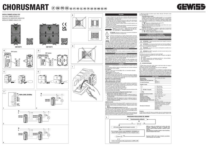
Nexta Tech MCU-SEN4 User manual

Control unit with dimmer function for single colour LEDs
with voltage, 12-24 VDC, 4 outputs,
Max 2,5 A per output. RX radio 433.92 MHz,
MCU-SEN4
MNLMCUSEN4ENV1.0
Nexta Tech
company brand of Team srl
via G.Oberdan 90, 33074
Fontanafredda (PN) - Italy
Ph. +39 0434 998682
Web: www.nexta-tech.com
INDEX
1 - PRODUCT FEATURES
1.1 - TECHNICAL DATA
1.2 - DESCRIPTION
2 - ELECTRICAL CONNECTIONI
2.1 - CONNECTION DIAGRAM
2.2 - DESCRIPTION OF CONNECTIONS
3 - USE OF THE CONTROL UNIT
3.1 - USE VIA RADIO
4 - RADIO PROGRAMMING
4.1 - RADIO PROGRAMMING WITH THE ASSOCIATION OF THE SERIAL NUMBER
4.2 - PROGRAMMING WITH MANUAL ASSOCIATION
5 - ADVANCE SETTING
5.1 - FADE SETTING: GRADUAL SWITCH-ON
5.2 - FADE SETTING: GRADUAL SWITCH-OFF
5.3 - TIMED ON
6 - DELETION OF RADIO
7 - FACTORY SETTING
This procedure let you take the control unit back to factory settings.
FULL RESET OF THE CONTROL UNIT:
5.4 FACTORY SETTING
STEP 1
Position DIPs 1, 2, 3 and 4
to OFF-OFF-OFF-OFF.
DIP 1, 2, 3, 4=
OFF OFF OFF OFF
STEP 2
Press the button on the
receiver for a short time.
The LED comes on
and stays on.
SHORT
PRESSURE
STEP 3
Position DIPs 3 to ON.
The LED flashes 9 times to
confirm.
DIP 3=
ON

1
2
1.1 TECHNICAL DATA
1 - PRODUCT FEATURES
- Installation must be carried out only by qualified technicians in compliance with the electrical and
safety standards in force.
- All connections must be made with the power turned off.
- Use suitable cables.
- Do not cut through the aerial (see picture 1.1b)
- A suitably sized disconnection device must be set up on the electric power line that supplies the product.
- Disposal of waste materials must fully respect local standards.
WARNINGS
43mm
21mm 52mm
Led
Dip switches
Button
58mm
Pic.1.1a
Pic.1.1b Pic.1.1c
1.2 DESCRIPTION
This device is the miniature electronic control unit with dimmer function, for wireless control of singl colour constant
voltage LEDs, power supply12-24Vdce, 4 outputs version with maximum consumption of 2,5A per output.
Fade On and Off that can be set between 0 and 10 seconds and adjustable Timed On (Default 60 secondi).
The ISM (industrial, scientific and medical) radio frequency band guarantees a long range and zero interferances.
Simple programming with dip-switch, reduced dimensions with tabs for fixing with screws.
Pic.1.2a Pic.1.2b
12 - 24 Vdc
Max load 2,5A:
30 W (with 12Vdc) per output
60 W (with 24Vdc) per output
Single colour LED with
constant voltage
30
433.920mhz ISM
IP20
-20 +55 °C
52x43x21 mm
Power supply
Output
Type of load
N° programmable transmitters
Radio frequency
Protection rating
Operating temperature
Dimensions
Pic.1.2c
Power supply 12-24Vdc
Control unit MCU-Sensa with wireless radio receiver
Radio
transmitter
Led profile seat
Sensor Sensa with wireless radiotransmitter
Sensor seat
Magnet (only for Sensa M version)
Led strip profile
Door

3
4
1234567
Pic.2.1
2.1 CONNECTION DIAGRAM
2 ELECTRICAL CONNECTIONS
12 to 24 VDC
power supply
(choose a power supply
compatible with the
load to be controlled
in terms of
voltage and power)
Loads with constant voltage
from 12 to 24VDC
(choose a loadthat's compatible
with the powersupplyin terms
of voltage and power)
Terminals 1-2 are reserved for
a 12 to 24 V power supply.
This voltage must be the
same as that acceptedby
the load as output.
TERMINAL
1
2
3
4
5
6
7
DESCRIPTION
Power supply -
Power supply + (12-24V)
Output +24V
Output 1 -
Output 2 -
Output 3 -
Output 4 -
- Use wires with a suitable cross-section for the load connected.
- Multiple buttons or loads can be connected by using parallel
cabling.
2.2 DESCRIPTION OF CONNECTIONS
LN
- (In)
+ (In)
+ (Out)
- (Out1)
- (Out2)
- (Out3)
- (Out4)
L: Brown
N: Blue
- Black
+ Red
POWER SUPPLY
OUTPUT: 12V/24V
-
+-
+-
+-
+
3 USE OF THE CONTROL UNIT
This control unit is set up to be activated by sensors or remote controls for automatic control of lights.
These devices must be programmed in order to control the loads, see paragraph 4.
By default, when a sensor intervenes or a command is sent by remote control, the associated lights come on for 60
seconds.
The control unit can also be commanded by transmitters, see paragraph 4.2 for the association procedure.
If the transmitter is a generic type, its operation will be as follows:
Short press= ON/OFF Long press= dimmer up/dimmer down
If the transmitter is multifunctional, refer to the transmitter manual, to the paragraph entitled "commands sent by the
transmitter", bearing in mind that it is a "dimmer" device.
NOTE: the lights are on a timer for 60 seconds.
If you want to change this value, see paragraph 5.3.
3.1 USE VIA RADIO
Radio
transmitters
Sensors

3
4
1234567
Pic.2.1
2.1 CONNECTION DIAGRAM
2 ELECTRICAL CONNECTIONS
12 to 24 VDC
power supply
(choose a power supply
compatible with the
load to be controlled
in terms of
voltage and power)
Loads with constant voltage
from 12 to 24VDC
(choose a loadthat's compatible
with the powersupplyin terms
of voltage and power)
Terminals 1-2 are reserved for
a 12 to 24 V power supply.
This voltage must be the
same as that acceptedby
the load as output.
TERMINAL
1
2
3
4
5
6
7
DESCRIPTION
Power supply -
Power supply + (12-24V)
Output +24V
Output 1 -
Output 2 -
Output 3 -
Output 4 -
- Use wires with a suitable cross-section for the load connected.
- Multiple buttons or loads can be connected by using parallel
cabling.
2.2 DESCRIPTION OF CONNECTIONS
LN
- (In)
+ (In)
+ (Out)
- (Out1)
- (Out2)
- (Out3)
- (Out4)
L: Brown
N: Blue
- Black
+ Red
POWER SUPPLY
OUTPUT: 12V/24V
-
+-
+-
+-
+
3 USE OF THE CONTROL UNIT
This control unit is set up to be activated by sensors or remote controls for automatic control of lights.
These devices must be programmed in order to control the loads, see paragraph 4.
By default, when a sensor intervenes or a command is sent by remote control, the associated lights come on for 60
seconds.
The control unit can also be commanded by transmitters, see paragraph 4.2 for the association procedure.
If the transmitter is a generic type, its operation will be as follows:
Short press= ON/OFF Long press= dimmer up/dimmer down
If the transmitter is multifunctional, refer to the transmitter manual, to the paragraph entitled "commands sent by the
transmitter", bearing in mind that it is a "dimmer" device.
NOTE: the lights are on a timer for 60 seconds.
If you want to change this value, see paragraph 5.3.
3.1 USE VIA RADIO
Radio
transmitters
Sensors

5
6
Serial
Number
4.2 PROGRAMMING WITH MANUAL ASSOCIATION
A sensor/transmitter can be associated manually with this procedure.
PROCEDURE:
STEP 1
Position DIPs 1, 2, 3 and 4
to ON-ON-ON-ON.
DIP 1, 2, 3, 4=
ON ON ON ON
STEP 2
Press the button on
thereceiver for a
short time.
The LED flashes
SHORT
PRESSURE
SHORT
PRESSURE
STEP 3
Choose which output to make the device act on by
moving the relative dip switches to OFF.
In the example shown:
I want to programme the
sensor on output 3 and 4, I
position dip switches 3 and
4 to OFF
STEP 4
Press the button on
the receiver for a
short time.
The LED comes on
and stays on.
4 - RADIO PROGRAMMING
4.1 RADIO PROGRAMMING WITH THE ASSOCIATION OF THE SERIAL NUMBER
Default: serial number 1
With this procedure you can set a "serial number" for the receiver.
The serial number to be set can be from 1 to 20.
*You can also delete the serial number (by setting 21 flashes in step 3/4 of the procedure) so that only manually associa-
ted sensors/transmitters operate.
To make the devices work a procedure must be carried out to give the receiver and sensors the same "serial number".
PROCEDURE:
STEP 1
Position DIPs 1, 2, 3 and 4
to OFF-OFF-OFF-OFF.
DIP 1, 2, 3, 4=
OFF OFF OFF OFF
DIP 4= ON
STEP 3
Position DIP 4 to ON
The LED stays on.
STEP 2
Press the button on the
receiver for a short time.
The LED comes on
and stays on.
FLASHES SERIAL NUMBER
1 flash 1
2 flashes 2
3 flashes 3
4 flashes 4
5 flashes 5
6 flashes 6
7 flashes 7
8 flashes 8
9 flashes 9
10 flashes 10
11 flashes 11
FLASHES SERIAL NUMBER
12 flashes 12
13 flashes 13
14 flashes 14
15 flashes 15
16 flashes 16
17 flashes 17
18 flashes 18
19 flashes 19
20 flashes 20
21 flashes No serial
number set*
STEP 4
Press the button on the receiver for a short time count the number of flashes emitted by the LED:
SHORT
PRESSURE
SHORT PRESSURE
DURING THE FLASH
STEP 5
Press the button for a
short time during the
flash that corresponds
to the function desired
to end the count
OUT1
OUT2
OUT3
OUT4
STEP 5
Make a transmission with the transmitter to be saved
(see transmitter manual, paragraph entitled "transmitter
programming").
The LED on the receiver flashes 3 times to signal
that it has been received and turns off
ATTENTION
To delete the manually associated transmitters from the memory, carry out the reset procedure shown in paragraph 5.4.
MAKE A TRANSMISSION
WITH THE TRANSMITTER THE LED FLASHES 3 TIMES
NOTE:
Make a note on the label
of the "serial number" set,
for any future
maintenance work.
ON
1 2 3 4
5
SHORT
PRESSURE

5
6
Serial
Number
4.2 PROGRAMMING WITH MANUAL ASSOCIATION
A sensor/transmitter can be associated manually with this procedure.
PROCEDURE:
STEP 1
Position DIPs 1, 2, 3 and 4
to ON-ON-ON-ON.
DIP 1, 2, 3, 4=
ON ON ON ON
STEP 2
Press the button on
thereceiver for a
short time.
The LED flashes
SHORT
PRESSURE
SHORT
PRESSURE
STEP 3
Choose which output to make the device act on by
moving the relative dip switches to OFF.
In the example shown:
I want to programme the
sensor on output 3 and 4, I
position dip switches 3 and
4 to OFF
STEP 4
Press the button on
the receiver for a
short time.
The LED comes on
and stays on.
4 - RADIO PROGRAMMING
4.1 RADIO PROGRAMMING WITH THE ASSOCIATION OF THE SERIAL NUMBER
Default: serial number 1
With this procedure you can set a "serial number" for the receiver.
The serial number to be set can be from 1 to 20.
*You can also delete the serial number (by setting 21 flashes in step 3/4 of the procedure) so that only manually associa-
ted sensors/transmitters operate.
To make the devices work a procedure must be carried out to give the receiver and sensors the same "serial number".
PROCEDURE:
STEP 1
Position DIPs 1, 2, 3 and 4
to OFF-OFF-OFF-OFF.
DIP 1, 2, 3, 4=
OFF OFF OFF OFF
DIP 4= ON
STEP 3
Position DIP 4 to ON
The LED stays on.
STEP 2
Press the button on the
receiver for a short time.
The LED comes on
and stays on.
FLASHES SERIAL NUMBER
1 flash 1
2 flashes 2
3 flashes 3
4 flashes 4
5 flashes 5
6 flashes 6
7 flashes 7
8 flashes 8
9 flashes 9
10 flashes 10
11 flashes 11
FLASHES SERIAL NUMBER
12 flashes 12
13 flashes 13
14 flashes 14
15 flashes 15
16 flashes 16
17 flashes 17
18 flashes 18
19 flashes 19
20 flashes 20
21 flashes No serial
number set*
STEP 4
Press the button on the receiver for a short time count the number of flashes emitted by the LED:
SHORT
PRESSURE
SHORT PRESSURE
DURING THE FLASH
STEP 5
Press the button for a
short time during the
flash that corresponds
to the function desired
to end the count
OUT1
OUT2
OUT3
OUT4
STEP 5
Make a transmission with the transmitter to be saved
(see transmitter manual, paragraph entitled "transmitter
programming").
The LED on the receiver flashes 3 times to signal
that it has been received and turns off
ATTENTION
To delete the manually associated transmitters from the memory, carry out the reset procedure shown in paragraph 5.4.
MAKE A TRANSMISSION
WITH THE TRANSMITTER THE LED FLASHES 3 TIMES
NOTE:
Make a note on the label
of the "serial number" set,
for any future
maintenance work.
ON
1 2 3 4
5
SHORT
PRESSURE

7
8
Default: 0,5s
This procedure means you can set the duration of the switch-on time.
PROCEDURE:
5.2 FADE SETTING: GRADUAL SWITCH OFF
STEP 1
Position DIPs 1, 2, 3 and 4
to OFF-OFF-ON-ON.
DIP 1, 2, 3, 4=
OFF OFF ON ON
STEP 2
Press the button on the
receiver for a short time.
The LED comes on
and stays on.
SHORT
PRESSURE
FLASHES SWITCH-OFF TIME
1 flash immediate OFF
2 flashes OFF ~ 0,5s
3 flashes OFF ~ 2s
4 flashes OFF ~ 4s
5 flashes OFF ~ 10s
STEP 3
Press the button on the receiver for a short time
count the number of flashes emitted by the LED:
SHORT
PRESSURE
SHORT PRESSURE
DURING THE FLASH
STEP 4
Press the button for a
short time during the
flash that corresponds
to the function desired
to end the count
Default: 0,5s
This procedure means you can set the duration of the switch-on time.
PROCEDURE:
5.1 FADE SETTING: GRADUAL SWITCH ON
STEP 1
Position DIPs 1, 2, 3 and 4
to ON-ON-OFF-OFF.
DIP 1, 2, 3, 4=
ON ON OFF OFF
STEP 2
Press the button on the
receiver for a short time.
The LED comes on
and stays on.
SHORT
PRESSURE
FLASHES SWITCH-ON TIME
1 flash immediate ON
2 flashes ON ~ 0,5s
3 flashes ON ~ 2s
4 flashes ON ~ 4s
5 flashes ON ~ 10s
STEP 3
Press the button on the receiver for a short time
count the number of flashes emitted by the LED:
SHORT
PRESSURE
SHORT PRESSURE
DURING THE FLASH
STEP 4
Press the button for a
short time during the
flash that corresponds
to the function desired
to end the count
5 - ADVANCE SETTING

9
10
STEP 1
Position DIPs 1, 2, 3 and 4
to ON-OFF-ON-OFF.
DIP 1, 2, 3, 4=
ON OFF ON OFF
STEP 2
Press the button on the
receiver for a short time.
The LED comes on
and stays on.
SHORT
PRESSURE
Default: 60 seconds
This process is used to set the time for which the Leds stays on before an automatic switch off.
PROCEDURE:
5.3 TIMED ON
STEP 3
Press the button on the receiver for a short time
count the number of flashes emitted by the LED:
SHORT
PRESSURE
SHORT PRESSURE
DURING THE FLASH
STEP 4
Press the button for a
short time during the
flash that corresponds
to the function desired
to end the count
FLASHES TIMED ON
1 flash No timing
2 flashes 5 seconds
3 flashes 30 seconds
4 flashes 60 seconds
5 flashes 90 seconds
6 flashes 120 seconds
7 flashes 180 seconds
8 flashes 5 minute
9 flashes 10 minute
10 flashes 30 minute
11 flashes 1 hour
These procedures let you delete from the memory transmitters that have already been programmed.
This procedure will delete all the manually associated transmitters (see paragraph 4.2) and the serial number of
the control unit will be taken back to 1.
6 - DELETION OF TRANSMITTERS
STEP 1
Hold the receiver button down
for 8 seconds.
The LED begins to flash
STEP 2
Make a transmission with the transmitter that
you want to delete.
The LED flashes quickly and turns off.
MAKE A TRANSMISSION
WITH THE TRANSMITTER LED FLASHES QUICKLY
LONG PRESSURE
(8 SECONDS)
STEP 1
Hold the receiver button down
for 8 seconds.
The LED begins to flash.
LONG PRESSURE
(8 SECONDS)
STEP 2
Press the button on the
receiver for a short time.
The LED starts flashing
quickly and turns off.
SHORT
PRESSURE
6.1 DELETION OF SINGLE TRANSMITTER
6.2 DELETION OF ALL THE SAVED TRANSMITTERS

Control unit with dimmer function for single colour LEDs
with voltage, 12-24 VDC, 4 outputs,
Max 2,5 A per output. RX radio 433.92 MHz,
MCU-SEN4
MNLMCUSEN4ENV1.0
Nexta Tech
company brand of Team srl
via G.Oberdan 90, 33074
Fontanafredda (PN) - Italy
Ph. +39 0434 998682
Email: [email protected]
Web: www.nexta-tech.com
INDEX
1 - PRODUCT FEATURES
1.1 - TECHNICAL DATA
1.2 - DESCRIPTION
2 - ELECTRICAL CONNECTIONI
2.1 - CONNECTION DIAGRAM
2.2 - DESCRIPTION OF CONNECTIONS
3 - USE OF THE CONTROL UNIT
3.1 - USE VIA RADIO
4 - RADIO PROGRAMMING
4.1 - RADIO PROGRAMMING WITH THE ASSOCIATION OF THE SERIAL NUMBER
4.2 - PROGRAMMING WITH MANUAL ASSOCIATION
5 - ADVANCE SETTING
5.1 - FADE SETTING: GRADUAL SWITCH-ON
5.2 - FADE SETTING: GRADUAL SWITCH-OFF
5.3 - TIMED ON
6 - DELETION OF RADIO
7 - FACTORY SETTING
This procedure let you take the control unit back to factory settings.
FULL RESET OF THE CONTROL UNIT:
5.4 FACTORY SETTING
STEP 1
Position DIPs 1, 2, 3 and 4
to OFF-OFF-OFF-OFF.
DIP 1, 2, 3, 4=
OFF OFF OFF OFF
STEP 2
Press the button on the
receiver for a short time.
The LED comes on
and stays on.
SHORT
PRESSURE
STEP 3
Position DIPs 3 to ON.
The LED flashes 9 times to
confirm.
DIP 3=
ON
Table of contents
