NextGen VIPER SC+ BASE User manual
Viper SC+ Base Station Order Numbers
US & Canada
The Viper SC+ Base Station for use in the US and Canada is available as:
•Standard Base Station
•Redundant Base Station or
•Redundant Base Station with Dual RF Port (Redundant Base - Dual RF)
140-5118-502 VHF 136-174 MHZ 6.25-50 kHz BW Viper SC+ Standard Base Station
140-5318-502 VHF 136-174 MHZ 6.25-50 kHz BW Viper SC+ Redundant Base Station
140-5318-503 VHF 136-174 MHZ 6.25-50 kHz BW Viper SC+ Redundant Base - Dual RF
140-5128-504 VHF 215-240 MHZ 6.25-100 kHz BW Viper SC+ Standard Base Station
140-5328-504 VHF 215-240 MHZ 6.25-100 kHz BW Viper SC+ Redundant Base Station
140-5328-505 VHF 215-240 MHZ 6.25-100 kHz BW Viper SC+ Redundant Base - Dual RF
140-5148-302 UHF 406.1125-470 MHZ 6.25-50 kHz BW Viper SC+ Standard Base Station
140-5348-302 UHF 406.1125-470 MHZ 6.25-50 kHz BW Viper SC+ Redundant Base Station
140-5348-303 UHF 406.1125-470 MHZ 6.25-50 kHz BW Viper SC+ Redundant Base - Dual RF
140-5148-502 UHF 450-512 MHZ 6.25-50 kHz BW Viper SC+ Standard Base Station
140-5348-502 UHF 450-512 MHZ 6.25-50 kHz BW Viper SC+ Redundant Base Station
140-5348-503 UHF 450-512 MHZ 6.25-50 kHz BW Viper SC+ Redundant Base - Dual RF
140-5198-304 UHF 880-902 MHZ 12.5-100 kHz BW Viper SC+ Standard Base Station
140-5398-304 900 880-902 MHZ 12.5-100 kHz BW Viper SC+ Redundant Base Station
140-5398-305 900 880-902 MHZ 12.5-100 kHz BW Viper SC+ Redundant Base - Dual RF
140-5198-504 900 928-960 MHZ 12.5-100 kHz BW Viper SC+ Standard Base Station
140-5398-504 900 928-960 MHZ 12.5-100 kHz BW Viper SC+ Redundant Base Station
140-5398-505 900 928-960 MHZ 12.5-100 kHz BW Viper SC+ Redundant Base - Dual RF
ETSI/AS/NZ Compliant
The Viper SC+ Base Station for use in the European Union (ETSI), Australia (AS), and New Zealand
(NZ) is available as:
•Standard Base Station
•Standard Base Station with Dual RF Port (Standard Base - Dual RF)
•Redundant Base Station or
•Redundant Base Station with Dual RF Port (Redundant Base - Dual RF)
(All units ETSI/AS/NZ)
140-5118-600 VHF 142-174 MHZ 12.5-25 kHz BW Viper SC+ Standard Base Station
140-5118-601 VHF 142-174 MHZ 12.5-25 kHz BW Viper SC+ Standard Base - Dual RF
140-5318-600 VHF 142-174 MHZ 12.5-25 kHz BW Viper SC+ Redundant Base Station
140-5318-601 VHF 142-174 MHZ 12.5-25 kHz BW Viper SC+ Redundant Base - Dual RF
140-5148-400 UHF 406.1125-470 MHZ 12.5-25 kHz BW Viper SC+ Standard Base Station
140-5148-401 UHF 406.1125-470 MHZ 12.5-25 kHz BW Viper SC+ Standard Base - Dual RF
140-5348-400 UHF 406.1125-470 MHZ 12.5-25 kHz BW Viper SC+ BW Redundant Base
140-5348-401 UHF 406.1125-470 MHZ 12.5-25 kHz BW Viper SC+ Redundant Base - Dual RF
140-5148-600 UHF 450-512 MHZ 12.5-25 kHz BW Viper SC+ Standard Base Station
140-5148-601 UHF 450-512 MHZ 12.5-25 kHz BW Viper SC+ Standard Base - Dual RF
140-5348-600 UHF 450-512 MHZ 12.5-25 kHz BW Viper SC+ Redundant Base Station
140-5348-601 UHF 450-512 MHZ 12.5-25 kHz BW Viper SC+ Redundant Base - Dual RF
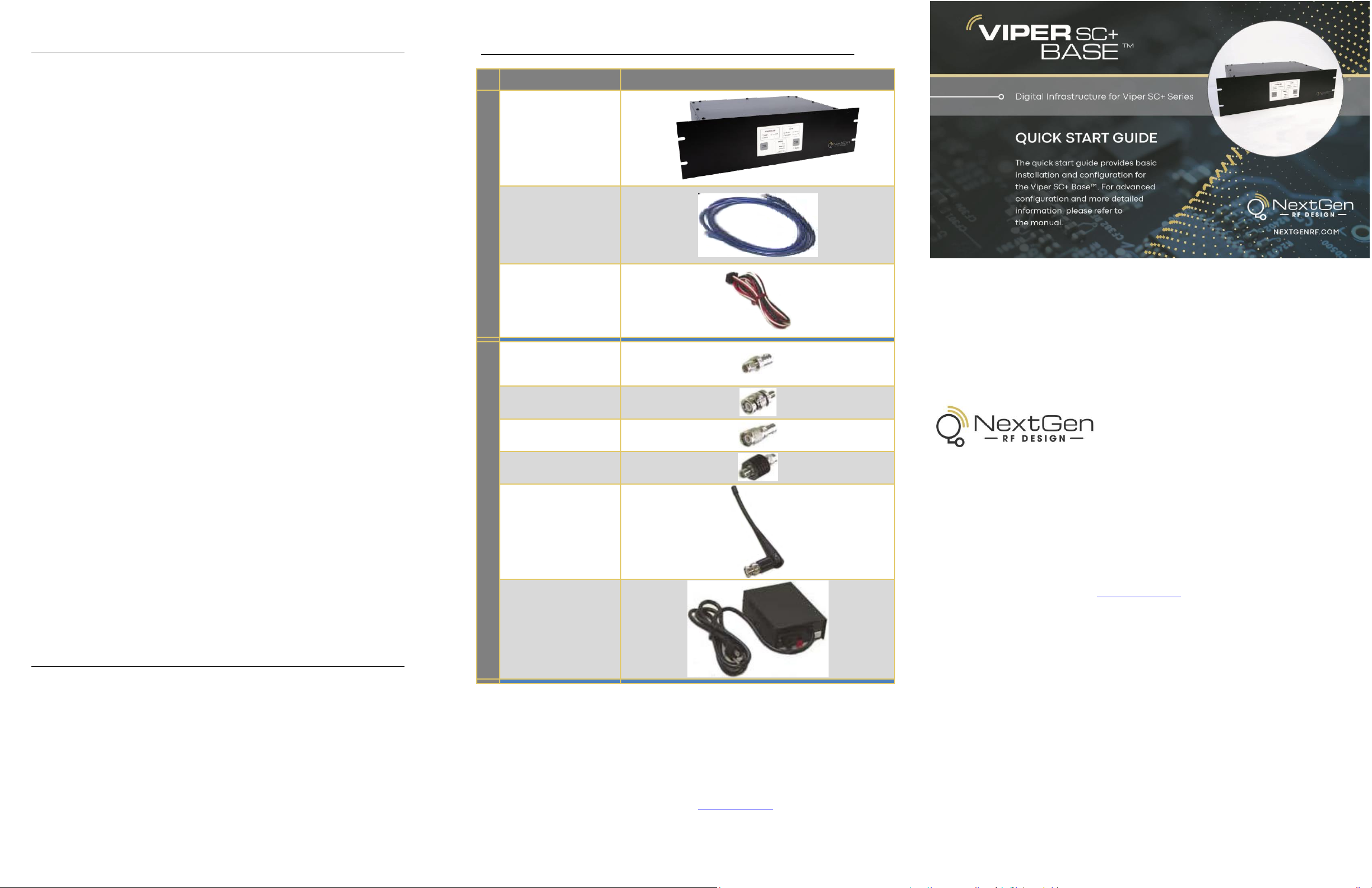
Package Contents
Your Viper SC+ Base Station package contains:
•(1) Viper SC+ Base Station (Configured as per part number above)
•(1) 60 in. CAT-5 Ethernet Cable
•(1) Power Cable
•(1) Start Up CD-ROM and Product Documentation Card
Kit Components
Description
Item
Basic Unit
Viper SC+ IP Router
60 in. Cat 5 Ethernet
Cable
Power Cable
2- and 3-Piece Kit Additional Items
SMA Male to BNC
Female Connector
SMA Female to BNC
Male Connector
TNC Male to BNC
Female Connector
Mini Circuits 5 W 20
dB Attenuator
Flex Rubber Duck
Antenna
(VHF, UHF, or 900
MHz)
120 VAC to 13.8 VDC
4 A Power Supply
Any changes or modifications not expressly approved by the party responsible for compliance (in the country
where used) could void the user’s authority to operate the equipment. NextGen RF reserves the right to update
its products, software, or documentation without obligation to notify any individual or entity. Product updates
may result in differences between the information provided and the product shipped. For access to the most
current product documentation and application notes, visit www.nextgenrf.com.
ABOUT NEXTGEN RF
NextGen RF is a USA owned and operated engineering services company providing valuable
wireless design expertise on a variety of products, ranging from design consultation to fully turnkey
product development. Because we know design, NextGen RF has become the chosen partner for
companies worldwide who require a high level of design expertise and responsiveness for their
product development. We understand the difficulties of implementing RF solutions in designs and
have a proven track record of helping clients efficiently meet their design objectives and
requirements. We focus on process-oriented engineering from discovery and idea generation,
definition of product requirements and specifications to design, verification and ultimately factory
introduction. For more information visit www.nextgenrf.com
© 2009-2021 NextGen RF Design
PN 004-5100-000 Rev. B
All specifications are typical and
subject to change without notice.
NG_Version03.21
NextGen RF
2130 Howard Drive W
North Mankato, MN 56003
507.514.6246
www.nextgenrf.com
SETUP AND CONFIGURATION
These instructions allow you to set up a Viper SC+ Base Station to verify basic unit operation and
experiment with network designs and configurations. To eliminate unnecessary disruption of traffic
on the existing network while you become familiar with the Base Station, you should use a network
IP subnet address that does not overlap with subnets currently in use in your test area.
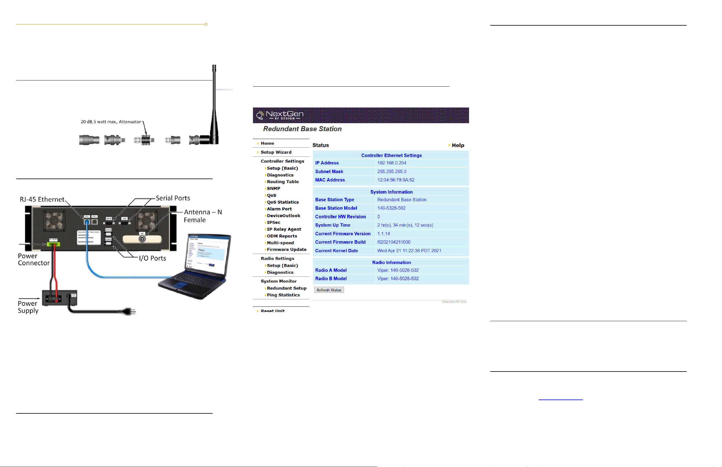
Antenna & Attenuator Connection
An Rx/Tx antenna is required for basic operation. Assemble antenna and connectors as
shown in the accompanying figure. Antenna and connectors are sold separately.
Note: It is important to use attenuation between all demo units in the test network to reduce the amount of
signal strength in the test environment.
Device Connections
Refer to the diagram below for proper device connections.
Connect an Ethernet cable to the first LAN port of the Viper SC+ and connect the other end into the
Ethernet port of your PC.
Primary power for the Viper SC+ must be within 10-30 V DC and must be capable of providing:
•10 W supply for Tx at 1 W
•40 W supply for Tx at 5 W or
•60 W supply for Tx at 10 W
Viper SC+ Demo kits include a power supply with spring terminals. Observe proper polarity when
connecting the cables to the power supply. The white wire must be connected to the red wire or B+
supply, as shown in the above figure.
Accessing the Viper SC+ Web Server
The Viper SC+ Base Station is configured via a Web-browser interface and contains a DHCP server
which will automatically assign an IP address to your PC, however in some cases it may be
necessary to change the network settings on the PC to accept the IP address assigned by the Viper
DHCP server.
Step 1 Enable a network connection with the following LAN settings. In the Internet Protocol
(TCP/IP) Properties window, select Obtain an IP address automatically and Obtain DNS server
address automatically. Click OK and close.
Step 2 Open a Web browser and enter 192.168.205.254 in the Address bar. When the connection
Login window appears, enter the Username: admin and the Password: ADMINISTRATOR (both
admin and ADMINISTRATOR are case-sensitive) and click OK.
Antenna & Attenuator Connection
Once you have logged in you will see the Home page of the Viper Web Interface as shown in the
following figure. Arranged vertically on the left side is the main navigation menu.
For quick setup, select Setup Wizard (beneath Home) from the main menu (along the left of the
page). The first page of the Viper SC+ Setup Wizard is displayed.
The Setup Wizard consists of four (4) steps. Each step is presented as a single page with a few
simple options to fill in or select from. Each of the four pages for each step of the Setup Wizard
contain the basic configuration settings that are most required to select or change to set up the
Viper SC+ Base Station for specific functionality. Read the instructions for each page carefully.
Instructions for each of these steps are provided on the web page for the step.
The Setup Wizard steps are as follows
Step Ethernet IP Address/Subnet and Login Security: Ethernet IP Address, Username and
Password. (× 2 for Redundant Radio models.)
Step LAN Configuration: Ethernet IP Address / Subnet Mask of the Base Station controller
board. (Must be on same subnet as internal radio or radios.)
Step Ping Settings: Primary and Secondary Ping IP Address, Ping Timer, and Ping Failure
Threshold.
Step Static Routes: Allows you to build a Routing Table by adding known static routes.
Setup complete: Click Finish to save and apply the Setup Wizard settings.
Setup Wizard Quick Setup
Enter the following in the Setup Wizard for quick setup. Click Next as you complete each
page in sequence. (You can click Previous to review settings in a previous page if needed.)
Step Radio A Configuration (and Radio B Configuration, if Redundant Base Station)
Note: A Redundant Base Station contains two internal Viper radios. The
purpose of the redundancy is so that if an error is detected in the primary
radio, the Base Station Controller automatically switches to the backup radio.
For this reason, both internal Viper radios must be configured with the same
settings. Select Radio A and Select Radio B buttons allow you to manually
select which radio is currently the primary (active) radio.
- Ethernet IP Address: Enter an IP Address for the internal Viper radio(s).
This will be different, but on the same subnet as the controller board
(default Radio A / Radio B Ethernet IP Address = 192.168.205.1).
-Username: and Password: These fields are for the username and password
used to log on to the Internal Viper radio(s) (default Username = Admin;
Password = ADMINISTRATOR) Important: These are both case-sensitive.
Step LAN Configuration: Enter the Ethernet IP Address/Subnet Mask for the Base
Station controller board. The IP address for the controller board must be on
the same subnet as the radio in the base station (both radios if redundant).
- Ethernet IP Address: Enter the Ethernet IP Address of the controller board
(default = 192.168.205.254).
- Ethernet Subnet Mask: Enter the Subnet Mask (default = 255.255.255.0).
Step Ping Settings: (Optional) to ping remote IP addresses to verify RF link is active.
- Primary Ping IP Address: Enter the IP Address of the primary remote that
pings will be sent to, to determine if the RF link is working (default = blank).
- Secondary Ping IP Address: Enter the IP Address of the secondary remote
to which pings will be sent if pings to the primary fail (default = blank).
- Ping Timer: Enter the amount of time (in multiples of 5 seconds) between
each ping that is sent (default = 0, disabled).
- Ping Failure Threshold: Enter the number of ping failures allowed
Step Static Routes & Routing Table: (Optional) Enter static routes into a table.
- Route Name: Enter a name for the route by which you will recognize the
route entry in the Routing Table displayed in the lower part of the page.
- Destination Address: Enter the IP Address of the destination network.
(This is a network name and not an actual IP address.)
- Gateway IP Address: Enter the IP Address of the local gateway.
- Metric: Enter a number ranging from 1 to 65,535. Generally, the lower the
metric value, the higher the priority. Typically set to 1.
- Click Add to add the route you have defined to the Routing table below.
Click Finish to finish the Setup Wizard. Your unit will now function with the new configuration.
Check for Normal Operation
To simulate data traffic over the radio network, use the PC connected to the Viper SC+ Ethernet
port to Ping each unit in the network multiple times. For more information about configuring the
Viper SC+, refer to the Viper SC+ Base Station User Manual (PN 001-5100-000).
Technical Support
For assistance with this product, contact NextGen RF technical support.
Email support@nextgenrf.com
Phone507.514.6246
Or visit our website at www.nextgenrf.com.
This manual suits for next models
30


