Nextlevel Acoustics UM1 User manual
USER MANUAL

2
Limited Warranty
JS Speaker Technology LLC guarantees the UM-1 to be free of defects
for the product’s warranty period of 5 years.
The warranty period begins on the original date of shipping. The lim-
ited warranty is intended only for the original purchaser. The warran-
ty will be void if the bracket is modified in anyway or not installed cor-
rectly, Including overloading, abuse, or use for any purpose other than
specified in these directions. The UM-1 is for indoor use only and any
use outdoors will void this warranty.
JS Speaker Technology LLC is not liable for any damage or injury
caused from the use of or the inability to use our bracket. To the maxi-
mum extent permitted by applicable law, JS Speaker Technology, LLC
disclaims any responsibility for incidental or consequential damages.
Additional terms and limited warranty conditions that apply to this prod-
uct are listed on the Next Level Acoustics website at:
www.nextlevelacoustics.com/warranty.
3
Next Level UM-1 Bracket
Thank you for purchasing the UM-1 mounting bracket. Please read the di-
rections thoroughly and plan how the mount would be best installed for its
intended use. Failure to do so may result in Damage, Personal Injury, or
voiding the warranty. It is the installer’s responsibility to ensure all compo-
nents are properly installed. JS Speaker Technology LLC is not responsible
for any damage or injury resulting from improper mounting or use of the UM
-1 bracket.
These instructions are only a guide and the installer is responsible for the
correct and secure mounting of all associated products. Please follow all
manufactures instructions for any product being installed with the UM-1
bracket. Please note: Each Setup will be different and these directions may
not account for every situation. The person installing the bracket should have
experience mounting load bearing assemblies. For any questions or con-
cerns, please contact technical support at Next Level Acoustics at 617-237-
CAUTION: The UM-1 is intended for use only
within the maximum weights denoted below. Use
with heavier than the maximum weights indicated
may result in instability causing possible serious
injury or damage. Review all relevant manuals to
ensure that the setup can handle the load.
12-15 lbs. when mounting above the TV using the stock TV stand
(max weight varies depending upon how wide the stock TV base
is)
12-20 lbs. when mounting above the TV in conjunction with a TV
mount
30 lbs. when mounting below the TV in conjunction with a TV
mount
DISCLAIMER: Maximum weight measures are only
guidelines and ARE NOT absolute! Use precaution
when mounting.

4
Specifications
Shipping Dimensions: 22” x 4” x 4”
Shipping Weight: 4 lbs.
Bracket Weight: 3 lbs.
Parts Included
(1) UM-1 Bracket Assembly (Sandwich, Vertical, Depth)
Hardware Included
(4) #10 Nuts and (4) 1/4” Nut
(4) #10 Bolts and (4) 1/4” Bolts
(4) #10 5/8” Screws and washers (mounting to Elite and Fusion
products)
PLEASE READ: May require spacers between the UM-1 and TV
mount when using lower profile mounts (sub 2.75″from wall to back
of the display) due to the increased depth adjustment capabilities of this
bracket system
Mount Uses
The UM-1 is designed and tested to mount Fusion Series Soundbars and
Elite Enclosures below the TV when using a TV mount all within weight
guidelines
The UM-1 may be used to mount an Elite Enclosure or Fusion Series
Soundbar above the TV, but proceed with extreme caution ensuring that
the enclosure or soundbar is adequately secured to the bracket and is stable
to avoid damage or injury
How to build the UM-1 Bracket System
Assemble the UM-1 following the Figure 1 Bracket Setup diagram
below using the provided parts and hardware
Please note: There are left and right side parts to this assembly
(Vertical Support/Depth Support)

5
Height/Depth Support Adjustments
Height Adjustment is achieved by loosening the #10 Bolts as needed
and sliding the Vertical Support up and down on the Sandwich Sup-
port. For the sturdiest setup keep the #10 Bolts as far away from each
other as possible
The Depth Support can be adjusted by loosening the 1/4" Nuts with a
7/16” wrench. The Depth
Support can also be swapped
around to achieve additional
depth adjustment, see Figure
2 and Figure 2a for more
details
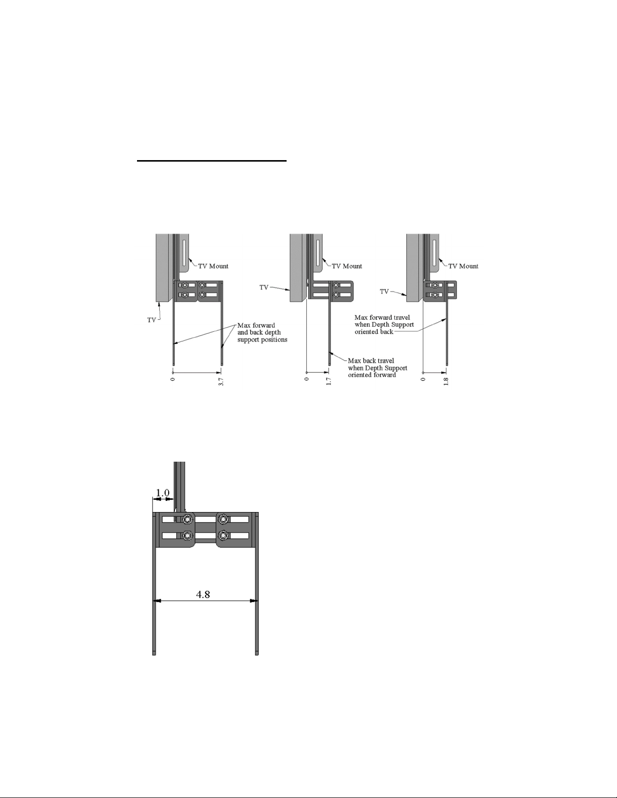
Figure 1 Bracket Setup
6
Depth Adjustments
Choose the proper depth adjustment permutation to perfectly line up the
Center Speaker, Soundbar, or Enclosure with the top or bottom edge of
the TV
**You can also swap the Depth Supports to the other
side of the bracket to achieve different anchor points**
Forward adjustment when the Depth Support
has clearance to move past 0
Figure 2
Figure 2a
7
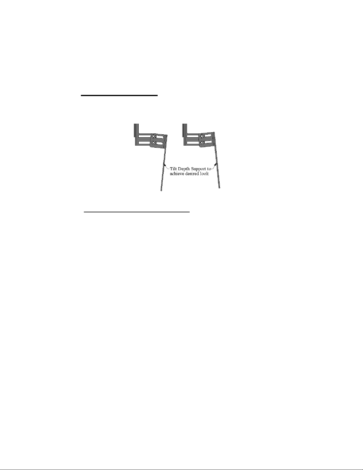
Tilt Adjustments
Choose the proper tilt adjustment angle to perfectly line up the Center
Speaker, Soundbar, or Enclosure with the top or bottom edge of the TV
Mounting Basic Recommendations
Elite Series Below the TV—Secure to the UM-1 Bracket Depth Sup-
port using two per bracket #10 5/8” long screws and associated wash-
ers per bracket (included)
Fusion Series Soundbars Below the TV—Drill a pilot hole and se-
cure to the UM-1 bracket Depth Support using two #10 5/8” long
screws and associated washers per bracket (included)
***When mounting an Elite Enclosure or Fusion Series
Soundbar above the TV use extreme caution ensuring
that the enclosure or soundbar is adequately secured to
the UM-1 bracket to avoid damage or injury***

8
Attaching to the TV
When using the TV manufacturers stand
Determine the optimal bracket placement and line the Sandwich sup-
port’s oval holes with the threaded holes on the back of your TV. Se-
cure the Sandwich Support to the back of the TV using the TV manu-
facturers recommended hardware
If your TV has bump outs, spacers
may be needed. (Spacers are not
included)
When mounting the TV to the wall
Mount the Sandwich Support be-
tween the TV Mount and the TV.
Make sure all 4 screws/bolts go
through the Sandwich Support and
anchor snugly into the threaded
holes on the back of the TV. Spacers
may be needed if the Sandwich Sup-
port interferes with the TV Mount.
For most dual hanger style TV
brackets spacers will not be needed
If your TV has bump outs, spacers
may be needed. (Spacers are not
included)
** Before mounting, consult
your TV’s owner manual / TV
mount’s manual and follow
all safety precautions.

9
Mounting above the TV example
Mounting below the TV example
Brackets can be swapped
Brackets can be swapped

10
Other manuals for UM1
1
Table of contents
Other Nextlevel Acoustics TV Mount manuals

Popular TV Mount manuals by other brands


Commercial Electric
Commercial Electric MB-52472 Use and care guide

Kogan
Kogan KA26VAC90EB user guide

Emos
Emos Gamma 600 ULTRA X installation instructions

PEERLESS
PEERLESS LWS210/BK Installation and assembly

Nordic
Nordic DELTACO ARM-0266 user manual

Future Automation
Future Automation PS Series Product guide


