Vivotek AM-21A User manual

IP Surveillance
Installation Guide
VIVOTEK Fixed Dome Series
Wall-mount Bracket
Using AM-21A wall-mount bracket
and compatible accessories
Rev. 1.1
Corresponding part number:
AM-21A: 909009301G AM-21A_V02

2
Compatible VIVOTEK Cameras
I
FD8167A, FD8169A, FD8177-H, FD8179-H, FD9171-HT, FD9181-HT, FD9165-HT, FD9167-H(T),
FD8177-HT, FD9187-H(T)V, FD9189-H(M)(T), FD8367A, FD8369A, FD8377-HV, FD8379-HV,
FD9371-(E)HTV, FD9381-(E)HTV, FD9365-(E)HTV, FD9365-HTVL, FD9367-(E)H(T)V, FD8377-(E)
HTV, FD9391-EHTV, FD9387-(E)H(T)V, FD9389-(E)H(M)(T)V, FD9360-H, IT9360-H, FD9368-HTV,
FD9380-H, IT9380-H, FD9388-HTV, IT9388-HT
You may also refer to VIVOTEK's website for the list of supported models. Support for other models can
be available through time.
Installation
II
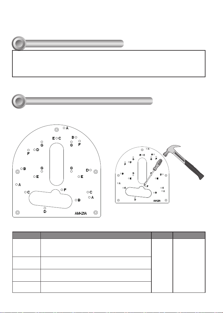
Above are the locations of different groups of mounting holes for matching different
cameras:
Hole Type Applicable Cameras Screw No. of screws
A
FD9371-(E)HTV, FD9381-(E)HTV, FD9365-(E)
HTV, FD9365-HTVL, FD9367-(E)H(T)V, FD8377-
(E)HTV, FD9391-EHTV, FD9387-(E)H(T)V
M4X10 3
BFD9171-HT, FD9181-HT, FD9165-HT, FD9167-
H(T), FD8177-HT, FD9187-H(T)V
CFD8367A, FD8369A, FD8377-HV, FD8379-HV,
FD9389-(E)H(M)(T)V, FD9368-HTV, FD9388-HTV
DFD8167A, FD8169A, FD8177-H, FD8179-H,
FD9189-H(M)(T)
Mounting Hole Denitions
Revision History:
* Rev. 1.0: Initial Release * Rev. 1.1: Added supported models and one more routing
hole is added.
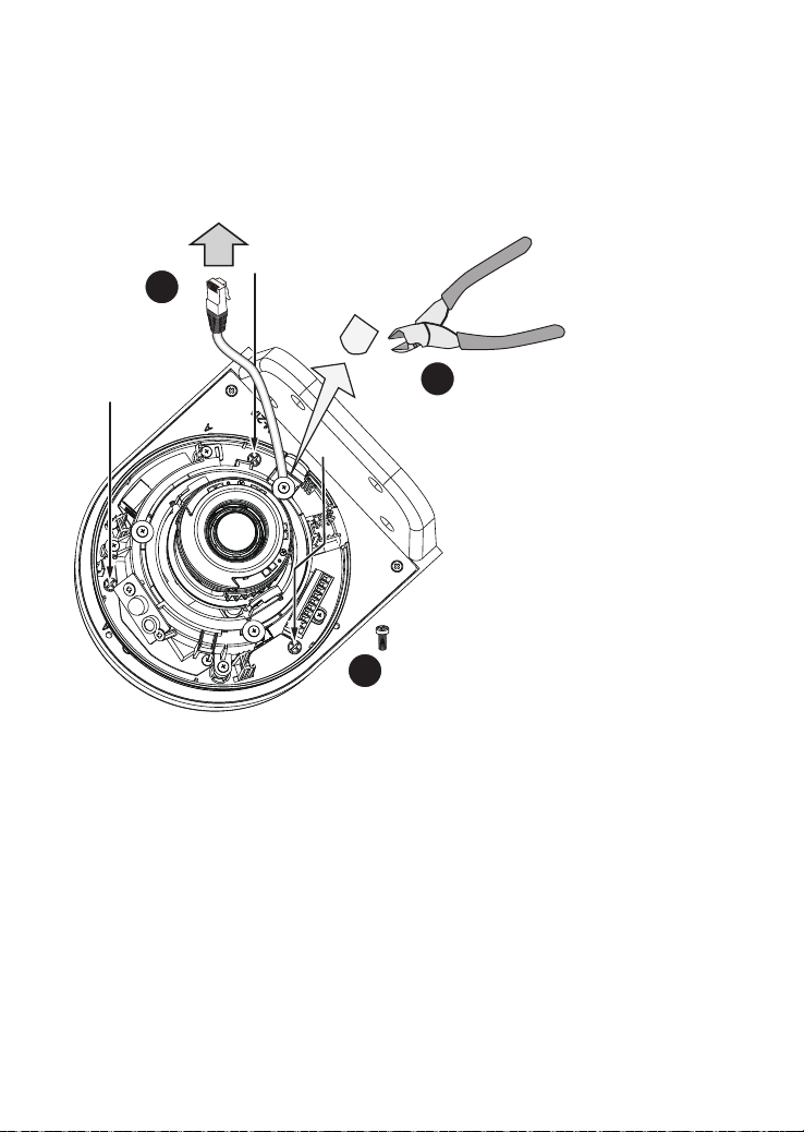
NOTE: You may need tools like hammer,
chisel, or a at-bade screwdriver to remove
the knock-out tab on the secondary routing
hole.

3
English
Refer to the table below for the description of the included screws:
Screw Description Quantity Applies to
M4X10 Phillips pan head 4 All camera
mounting holes
M4X25XD9 Phillips pan
head
4 Securing the
bracket to wall
Plastic anchors 4 Securing the
bracket to wall
NOTE:
1. It is presumed that this wall-mount bracket is installed with a hole drilled on the wall for
routing power lines, DI/DO, and Ethernet cables.
2. Route cables before you secure the wall-mount bracket to a wall.
3. For details on the cable connections with each camera, please refer to their Quick
Installation Guide.
For cabling and conguration details with each network camera, please refer to their
documentation.
Hole Type Applicable Cameras Screw No. of screws
EIT9388-HT
M4x10 3
FFD9360-H, FD9380-H
GIT9360-H, IT9380-H 4

4
Below is a general, sample procedure using a wall mount bracket:
1. Locate the position where you want to install the wall mount bracket and camera. Drill
holes on the wall for securing the bracket and for routing the cables.
2. Secure the bracket by hammering anchors into the wall and then fasten screws through
the four mounting holes on the bracket.
3. Route power lines and other cables through the wall and the bracket.
4. Remove the waterproof connectors from the camera.
5. Align the camera's mounting holes with the A holes. Secure the camera to the wall
mount bracket as shown below.
Aligned with A holes
IMPORTANT!
Wall Mount Installation - FD9371-(E)HTV, FD9381-(E)HTV, FD9365-(E)HTV,
FD9365-HTVL, FD9367-(E)H(T)V, FD8377-(E)HTV, FD9391-EHTV, FD9387-(E)H(T)V
The screws and mounting surface must be able to support a weight of 4 kg.

5
English
6. Proceed with initial setup such as enabling network access, focus tuning, or zooming.
When done, secure the outer dome cover.
NOTE:
Use the correct type of screws when installing cameras to the mounting cap. Refer to page
3 for the screw type. You will need to pass the cables through the waterproof connectors,
and then use a crimping tool to connect the cable wires to an RJ45 connector.
o
O
g
B
b
G
br
BR
1
2
3
4
5
6
7
8
o: white/orange stripe
O: orange solid
g: white/green stripe
B: blue solid
b: white/blue stripe
G: green solid
br: white/brown stripe
BR: brown solid

6
Aligned with B holes
6
5
7
Below is a sample procedure using the wall mount bracket and an FD9171:
1. Determine a hard surface wall location, and use the four mounting holes on the wall
mount bracket to mark the positions where holes will be drilled to secure the bracket.
Wall Mount Installation - FD9171-HT, FD9181-HT, FD9165-HT, FD9167-H(T),
FD8177-HT, FD9187-H(T)V
2. Drill holes on the wall for passing cables and for securing the wall mount bracket.
3. Secure the bracket by hammering anchors into the wall and then fasten screws.
4. Route power lines and other cables through the bracket and wall.
5. Use a cutting plier to remove the plastic tab on the pre-cut routing hole.
6. Pass cables through hole.
7. Secure camera to the wall mount bracket using the B holes and M4x10 screws.
8. Proceed with initial setup such as enabling network access, focus tuning, or zooming.
When done, secure the outer dome cover.

7
English
Below is a sample procedure using wall mount bracket and an FD8369A:
1. Determine a hard surface wall location, and use the four mounting holes on the bracket
to mark the positions where holes will be drilled to secure the bracket.
Wall Mount Installation - FD8367A, FD8369A, FD8377-HV, FD8379-HV, FD9389-
(E)H(M)(T)V, FD9368-HTV, FD9388-HTV
Aligned with C holes
2. Drill holes on the wall for securing the bracket and for routing cables.
3. Route cables through the wall and bracket.
4. Secure the wall mount bracket to the wall using the included screws and plastic
anchors.
5. You will need to pass cables through the waterproof connectors, and then use a
crimping tool to connect the cable wires to an RJ45 connector. See page 5.
6. Secure the camera to the bracket using the included screws.
7. Connect power lines and cables to the camera.
8. Proceed with initial setup such as enabling network access, focus tuning, or zooming.
When done, secure the outer dome cover.

8

9
English
Below is a general, sample procedure using a wall mount bracket with the FD8169A
camera:
1. Locate the position where you want to install the wall mount bracket and camera. Drill
holes on the wall for securing the bracket and for routing cables.
2. You can route cables through the hole in the center of the bracket and the space
beneath the camera.
3. Secure the wall mount bracket to the wall using the included plastic anchors and
screws.
4. Route cables through the crescent cutout on the side of camera.
5. Secure the camera to the bracket using 3 M4X10 screws.
6. Connect cables and you may now begin the initial connection and conguration.
Wall Mount Installation - FD8167A, FD8169A, FD8177-H, FD8179-H, FD9189-
H(M)(T)
4
Aligned with D holes
5

10
7. Attach dome cover to the camera.

11
English
Wall Mount Installation -
E: IT9388-HT; F: FD9360-H, FD9380-H; G: IT9360-H, IT9380-H
E / F / G
Aligned with

12
This page is intentionally left blank.
This manual suits for next models
1
Table of contents
Other Vivotek TV Mount manuals