NextWave Digital TDR-3200 User manual

Operating Instructions
TDR-3200
Australian Digital TV Receiver
2
Safety Instructions
WARNING
RISK ELECTRIC SHOCK
DO NOT OPEN
TO REDUCE THE RISK OF ELECTRIC SHOCK, DO NOT
REMOVE COVER(OR BACK). NO USER SERVICEABLE PARTS
INSIDE. REFER SERVICING TO QUALIFIED SERVICE
PERSONNEL.
This symbol indicates
important instructions
accompanying the product.
This symbol indicates "da ngerous
voltage" inside the product that
presents a risk of electric shock or
personal injury. !
Please read the following safety instructions carefully.
♦Do not overload wall outlets, extension cords or integral convenience receptacles as this can
result in a risk of fire or electrical shock.
♦Never allow liquids, spray or other materials to come into contact with the inside of the STB.
♦Unplug the STB from the wall outlet before cleaning.
♦Use a soft cloth to clean the exterior of the STB.
♦Allow clear space around the STB for sufficient ventilation.
♦Do not use the STB where it is exposed to direct sunlight or near a heater.
♦Never stack other electronic equipment on top of the STB.
♦Do not place the STB outdoors. Keep out of direct sunlight.
♦Do not connect or modify cables when the STB is plugged in.
♦Do not cover the STB or place it on a unit that emits heat.

33
Safety Instructions............................................. ...........................................................2
Quick Start Guide...........................................................................................................4
Front Panel / Rear Panel................................................................................................6
Remote Control..............................................................................................................8
Installation......................................................................................................................10
Getting Started.............................................................................................................18
User Functions.............................................................................................................21
Teletext..................................................................................................................21
Program Guide......................................................................................................22
Main Menu....................................................................................................................23
Language...............................................................................................................23
Configuration........................................................................................................24
Time Settings........................................................................................................25
Edit Programs........................................................................................................27
Channel Search....................................................................................................29
Change Password................................................................................................32
Parental Control....................................................................................................32
Games....................................................................................................................32
Troubleshooting.............................................................................................................33
Specifications..............................................................................................................34
Glossary of Terms...........................................................................................................35
Warranty Form.............................................................................................................37
Contents
4
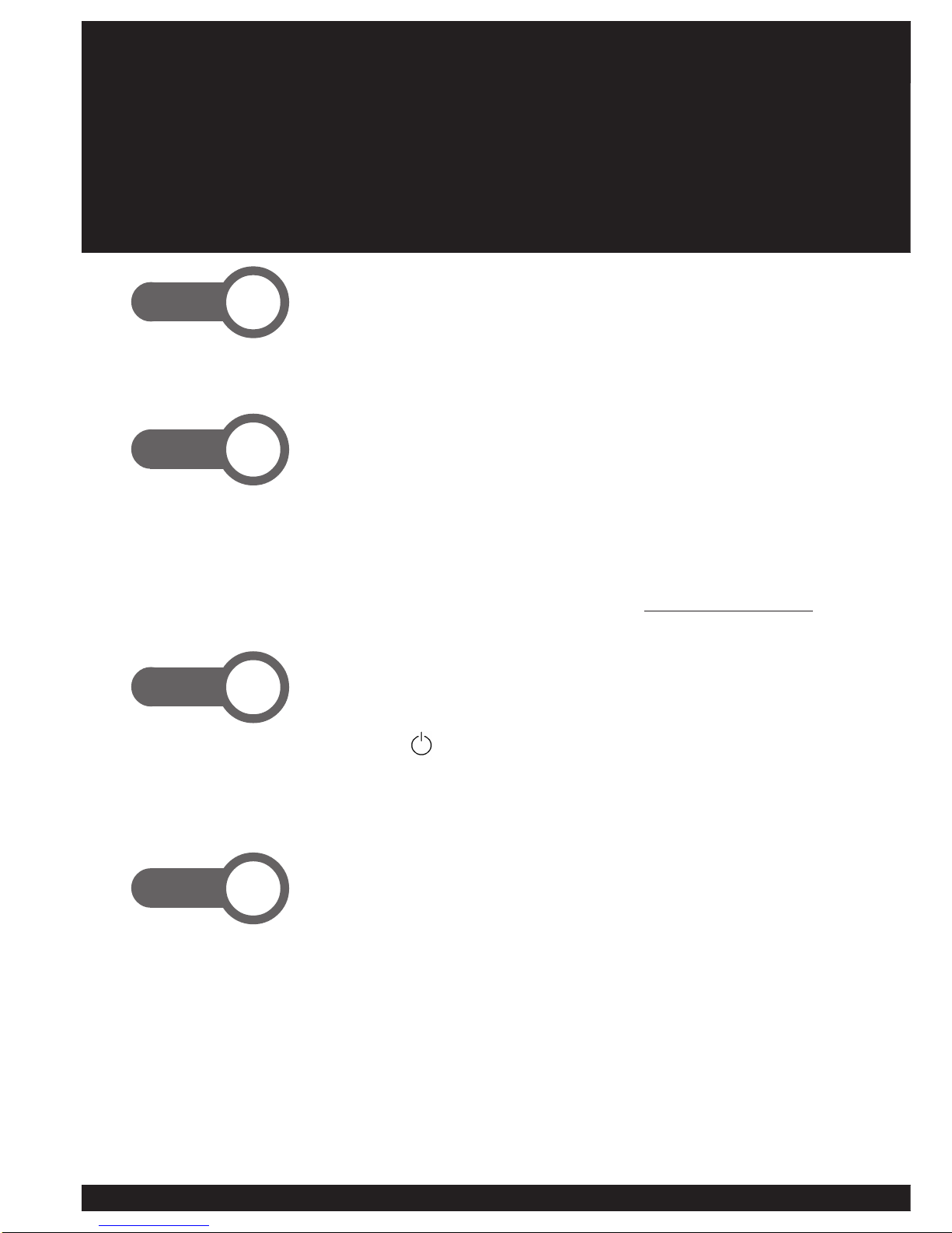
Connect your antenna to the ANT IN socket.
Connect Video and Audio lead between STB and VCR or TV.
- Connect video (yellow) plugs of supplied lead to VIDEO
OUT of STB to VIDEO IN of your TV or VCR.
- Connect audio (white & red) plugs into the AUDIO L-R
sockets on the STB and to AUDIO IN (L-R) of the VCR or TV.
For other connection options see pages 10-15 or visit www.nextwave-digital.com
Turn on STB.
- Power up STB at mains switch behind the decoder.
- Press STANDBY button on Remote Control Unit (RCU)
or the front panel button.
- NoPr will appear on the 4-digit front panel display. t0(xx)
will appear on the front panel display if the STB has
previously been scanned.
At Start-up, highlight (green) QUICK SCAN using
buttons. Press OK.
The STB will have no channels activated when first installed.
Press OK on AUTO SCAN and this will activate the scanning
process. The scan process should take a minute.
Step. 2
Step. 1
Step. 4
Step. 3
Quick-Start Guide
If you wish to operate the NextWave Australian Digital TV ‘Set Top Box’ (STB) before
reading the rest of this manual, use the following steps to get started quickly.
55
Remote Control
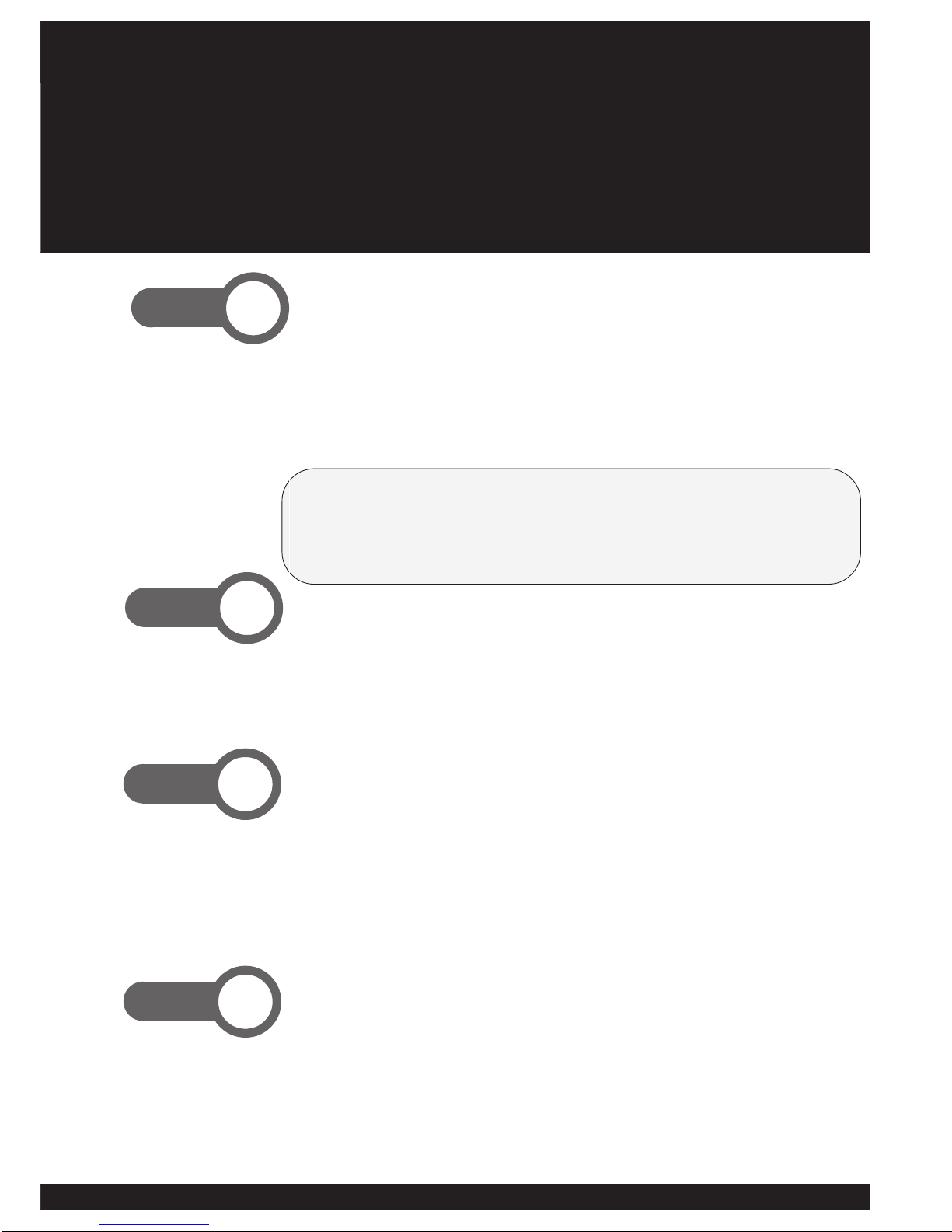
Observe signal strength bar and signal quality bar while
STB is scanning.
- Take note of the level indicators as this will determine the
consistency of your picture quality.
- Signals between 50%~70% may not allow pictures to be
constantly available. Signals below 50% may mean that no
picture will be available.
The F1 key will invoke the Quick Scan function at any time. This is particularly useful if
you take your digital receiver to other regions in Australia where the digital channel plan
is different from your own.
Quick scan will be useful when new digital services, e.g. new channels, ‘datacasting’ or
other kinds of digital TV services, become available.
Press EXIT followed by OK to view TV channels.
- Exit from the Channel Scan menu by pressing EXIT,
followed by OK to save the current channel plan.
- Change channels with the CH + / - or keys. Adjust the
aspect ratio to suit your TV using the WIDE button.
Press OK to display full Channel List.
-Once the picture is displayed, press OK to display the full
channel list. See page 20 for full details.
Step. 6
Step. 5
The rest of the manual contains detailed instructions for
installing and working with your new digital set top box.
Step. 7
Finish !
6
You have purchased a full featured standard definition digital set top box (STB).
This unit has a multitude of features and connections for all your digital TV needs.
Compact Size
Onscreen Games
Onscreen Teletext
Closed Captioning
Parental Control PIN
Super Fast Channel Scan
Favourite Channels Function
Internet Support Site
Simple Setup Key
Signal Indicator Bars
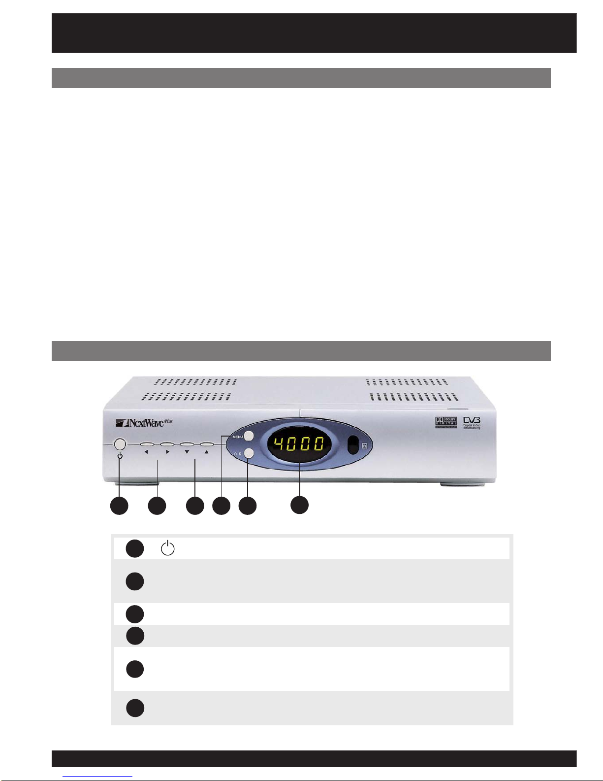
Front Panel
.edomnoitarepO/ybdnatSehttceleS
puslennahcegnahC.emulovehttsujdaotdnasgnittesegnahC txeteletehtniegap-bustceleS.egaptsilenoybnwoddna .edom
.nwoDdnapUlennahC
uneM .sunem-bushguorhtkcabpetS.uneMniaMyalpsiD
KO otdnaunemehtnimetidethgilhgihafonoitcelesmrifnoC- .petstxenehtotog .edomgniweivehtnitsillennahcoidaR/VTyalpsiD-
yalpsiDtigiD4 .rebmunlennahc)r(oidaRro)t(VTsyalpsiD .edomybdnatsniemitsyalpsiD
1 2
Features
Dolby Digital Audio
Optical Digital Out
Coaxial Digital Out
S-Video and Composite Video
RGBandComponent(Y,Cb,Cr) Video
RF output
2 x SCART outputs
Aspect Ratio (16:9, 4:3) Hot-Key
Software Upgradeable
Loop through capability
3 5 6
4
Front Panel & Features
6
5
4
3
2
1
77
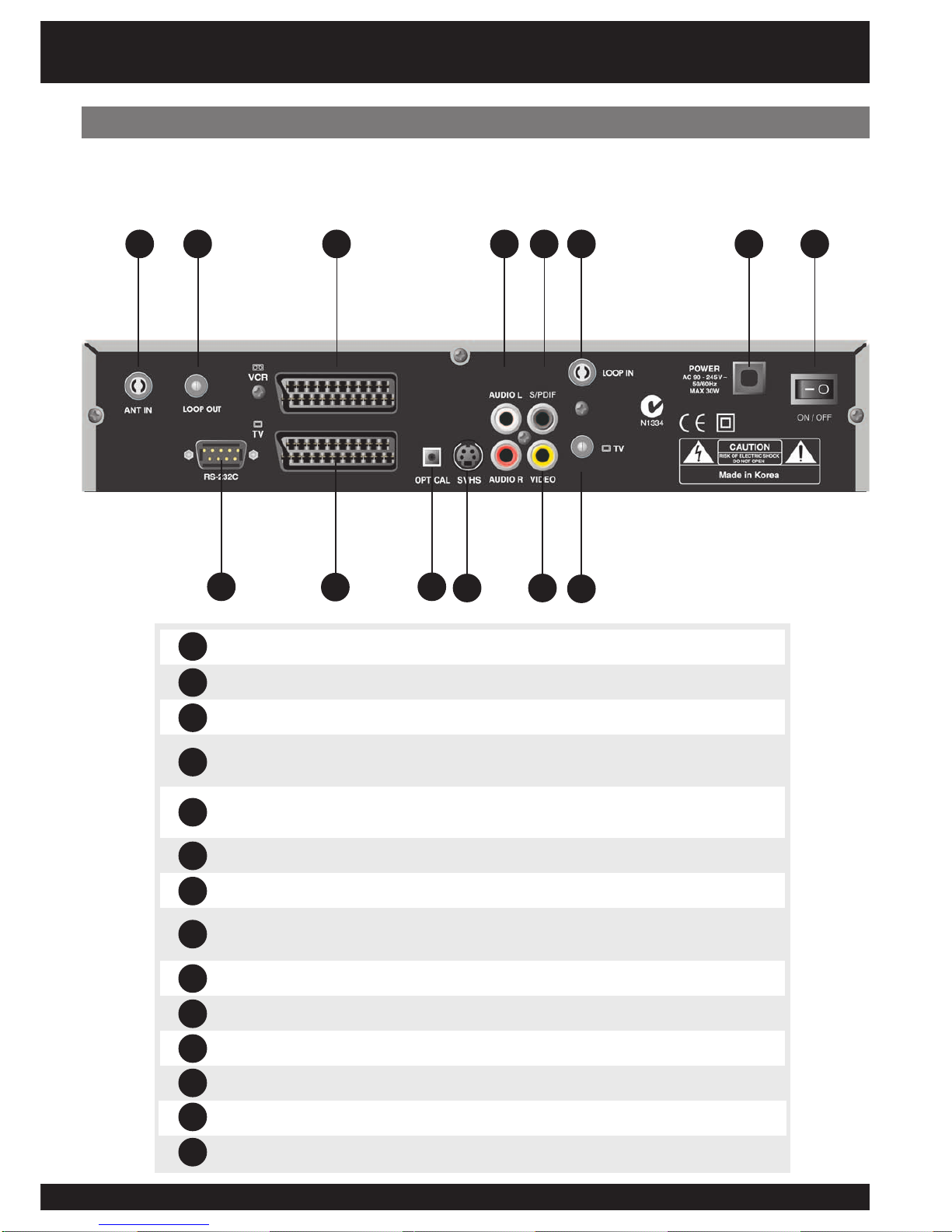
Rear Panel
1 2 4 8 9
710
13 14
NITNA .tupnilaireaVT)lanoitnevnoc(lairtserreT
TUOPOOL .NIPOOLottcennocotdesU.annetnamorflangissaemaS
232SRATAD .troPedargpUerawtfoS
TRACSRCV etuorotnottubXUAesU.tuptuodnatupnilangisswollA .)R/LoiduA&oedivetisopmoC(.BTShguorhtlangis
TRACSVT ,Y(tnenopmoCro)SBVC(etisopmoC,BGRhtiwlangistuptuO .R/LoiduA&)rC,bC
KNILSOTFIDP/S .rossecorPVAottcennoC.tuptuOoiduAlacitpO
oediV-S .elbacoediV-ShguorhtRCV/VTottcennoC
TFELOIDUA THGIROIDUA .teSVTrometsysiF-iHaotnoitcennocroftuptuooeretS
laixaoCFIDP/S .rossecorPVAottcennoC.tuptuOoiduAlaixaoC
TUOOEDIV .RCV/VTottcennoC.tuptuooediv)etisopmoC(SBVC
NIPOOL .TUOVTaivtuodepoolebotlangisroftupnI
VT .)RCV/VT.g.e(secivedrehtootgnideefroftuptuolaireaVT
DAELREWOP .ylppussniamCAV042ottcennoC
HCTIWSREWOP .BTSehtffo/nosnruT
1
2
3
4
5
6
7
8
Your NextWave TDR3100 digital TV receiver contains a wealth of connection options.
The following diagram illustrates and describes the connection options on the rear panel.
5
3 6
11
12
10
11
12
13
14
9
8
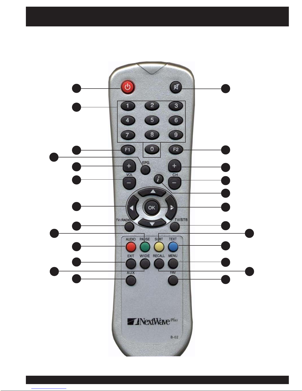
You can operate every function of the NextWave digital decoder using the buttons on the
remote control handset. Please read this section to help your understanding of each function.
1
3
7
9
12
2
8
10
11
13
6
14 15
24 25
18
20 21
19
1716
2322
5
4
Remote Control

99
.hctiwsybdnatS
.)etum(no/ffodnuosehtnruT
9~0 .sretcarahcretneotdnaslennahcegnahC
1F .noitcnuFnacS-kciuQsetavitcA
2F .evitcAtoN
GPE .unemscihpargnierutcipsetavitcA
-/+HC .nwodropuslennahcegnahC
-/+LOV .rewolrorehgihemulovehttsujdA
i.neercsehtnoxobnoitamrofnimargorpehtyalpsidotyeknoitamrofnI
nisegapegnahC.unemehtninwod/puevomdnaslennahcegnahC .edomtxeteleteht
dnapuslennahcegnahC.emulovehttsujdaotdnasgnittesegnahC .edomtxeteletehtniegap-bustceleS.egaptsilenoybnwod
KO otdnaunemehtnimetidethgilhgihafonoitcelesmrifnoC- .petstxenehtotog .edomgniweivehtnitsillennahcoidaR/VTyalpsiD-
OIDAR/VT .oidaRdnaVTneewtebhctiwS
BTS/VT .hguorhtpooLnoVTeugolanAdnaVTlatigiDneewtebhctiwS
ESUAP .emuserotsserP.erutciptnerrucehtezeerF
TBUS desolC“rofdesueraseltitbus,ailartsuAnI.seltitbusevomeR/yalpsiD .)CC(”gninoitpaC
OIDUA esuelbaliavasi)3CA.g.e(oiduaetanretlafI.kcartdnuostceleS .KOsserpdnatcelesotworra
TXET .txeteletllufstimsnartkrowteN7eht,ailartsuAnI.edomtxeteletretnE
TIXE .unemtnerrucamorfedomgniweivehtotnruteR
UNEM unemehtnipetsenokcabogotroyalpsiD
EDIW arof’xobretteL‘royalpsid)9:61(neercsediwrofoitartcepsatsujdA .VT3:4
LLACER egnahC.slennahcoidaR/VTsuoiverpdnatnerrucneewtebelggoT .edomtxeteletehtnisegap-bus
XUA .tuptuOdnatupnITRACSneewtebsehctiwS
VAF setiruovafehtyalpsiddnaneercsehtnotsilslennahcetiruovaftidE .edomtxeteletnisegap-busegnahC.edomediugVTehtnitsil
Remote Control
1
2
3
4
5
6
7 9
810
11
12
13
14
15
16
17
18
19
20
21
22
23
24
25

10
The following diagrams detail the most common ways of connecting the STB to your equipment.
Please Note: RF OUT, COMPOSITE(RCA), S-VIDEO, RGB or Component (Y,Cb,Cr) signlas are available at all times. Pluging in
to one socket does not deactivate the others. However, Component Out (Y, Cb, Cr) and RGB Out are only available via TV
SCART and have to be selected in the Video Configuration Menu. See page 24 for details.
1. Connect the coaxial cable from the
VHF/UHF Antenna to the AERIAL
socket on the rear panel of the STB.
3. Connect the SCART lead between
the main SCART socket on the TV
and the TV SCART socket on the
rear panel of the STB.
Connecting to a TV
Connecting to TV with SCART Input
Please Note: To accept the RGB signal, you may have to
enable SCART(RGB/Y,Cb,Cr) on your Television.
1. Connect the cable from the
Antenna to the AERIAL socket on
the rear panel of the STB.
2. Connect an RCA cable to
the VIDEO OUT socket on the
STB and the VIDEO-IN RCA
socket on your TV.
3. Connect an RCA cable to the
AUDIO OUT (L-R) socket on the
STB and the AUDIO IN (L-R) RCA
socket on your TV.
Please Note: If your TV set has S-Video inputs, better picture qulaity
can be achieved by using this connection.
SCART
S-Video
Composite Video (RCA)
1. Connect the VHF/UHF Antenna to the
AERIAL socket on the rear panel of the
STB.
2. Connect the S-Video lead between the
main S-Video socket on the TV and the
S-Video socket on the rear panel of the
STB.
3. Depending on your audio needs, link
audio output from any one of the three
types of audio connections.
Installation
1111
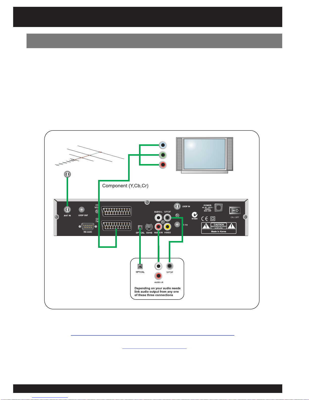
Connecting to a TV using Component (Y,Cb,Cr) output
Installation
1. Connect the coaxial cable from the Antenna to the ANT IN socket on the rear panel of the STB.
2. Connect a SCART to Component (Purchased separately) cable to the SCART TV socket on the STB
and the Component IN (Y,Cb,Cr) socket on your TV.
3. Component output needs to be activated via the Video Configuration menu. See page 24 for details.
4. Depending on your audio needs, link audio output from any one of the three types of audio connections.
We recommend quality SignalMAX Cable and Flyleads.
www.signalmax.com.au
12
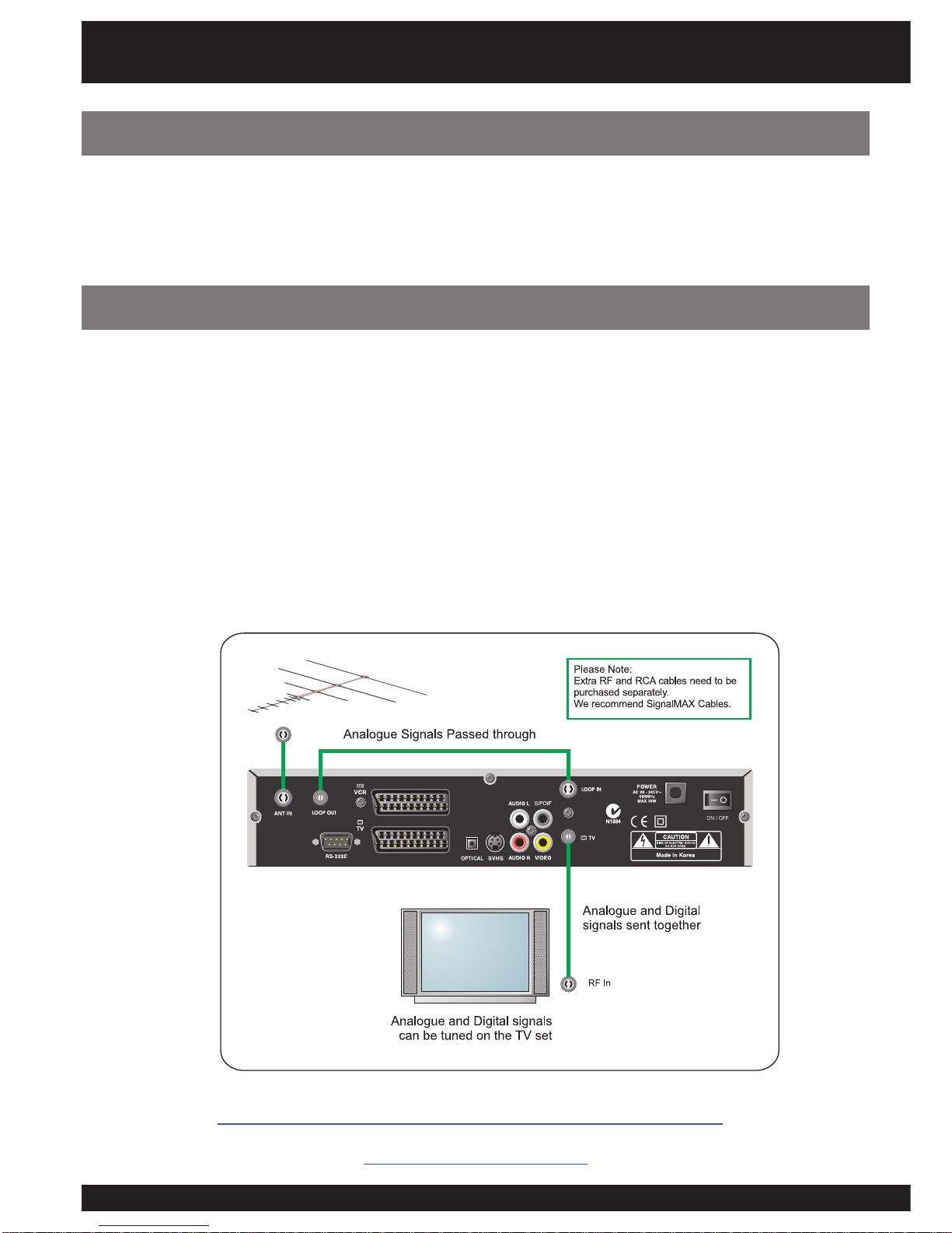
Where you want to view commercial digital channels and community analogue channels
through a single cable, follow these steps:
1. Connect the coaxial cable from the Antenna to the ANT IN socket on the rear panel of the STB.
2. Connect a RF Flylead (purchased separately) from the LOOP OUT sockect to the LOOP IN socket
on the rear of the STB.
3. Connect Flylead (purchased separately) to TV OUT on the STB and TV or RF IN on TV set.
- Tune TV in the UHF band for STB digital output. Refer to your TV user manual for tuning analogue channels.
- The RF output is programmable from ch 21-69. It is important to select appropriate RF output frequency to avoid interference.
- If loop through facility is not used, only digital channels will be available via TV (RF out) connection.
For other installation tips, please visit the NextWave Digital web site:
www.nextwave-digital.com
Use of RF Loop Through
Installation
Please Note: It is recommended to use two way splitters for noise free pictures instead of using this connection method.
Your set top box has the ability to loop through signals from other sources via the RF loop
through method or the SCART Loop through method. These options are ideal for TV sets
with limited inputs.
Loop Through Facility
1313
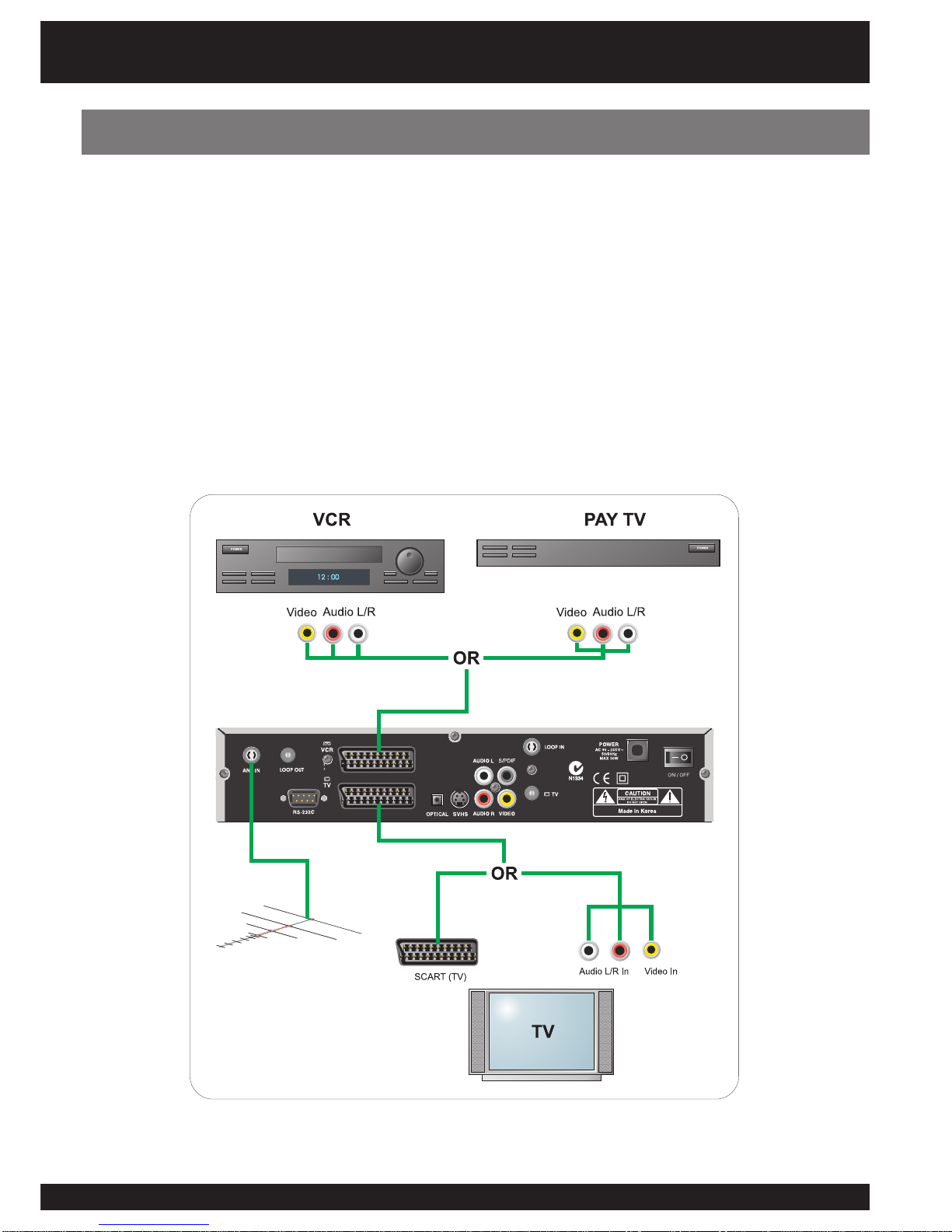
This function allows you to use the STB as a router.
1. Connect your VCR or PAY TV STB to the SCART (VCR) input.
2. Press the AUX button on the RCU.
3. The picture from your VCR or PAY TV STB will now appear on your TV set.
4. To watch output from set-top-box Press AUX button again.
- This signal can be routed through to the TV SCART output or the composite (RCA) outputs.
Both video signal and audio signal are routed.
Use of SCART Loop Through
Installation
Please Note: The switched output is available through the following connectors (RCA/SCART (TV)/RF Out).

14
- In this setup your VCR will have to be switched to AV/Line In mode. The signal from the
STB will now be routed through the VCR to the TV set as long as the VCR is switched on.
- To view VCR program and STB program select AV/Video on TV set.
- If you do not have AV Inputs on your TV set or they are being used for other purposes,
you can use the RF input on the TV set to view STB and VCR pictures.
- You can record programs from the STB on the VCR provided AV/Line in is selected.
Connecting a VCR - Method 1.
Please Note: Connecting a VCR in this way is only possible if your VCR has AV Inputs for Audio and Video. The VCR must
be in AV or Line In mode to record.
This method will allow you to watch a digital channel and record an analogue channel or vice
versa.
Connecting a VCR - Method 1.
Installation
1515
- This setup is identical to method 1 except your VCR does not need to be switched on for
digital signals to be received from the STB.
- Extra SCART-RCA cables need to be purchased for this setup.
- You can watch signal from STB on AV mode and record analogue signal from antenna
on the VCR on RF mode (2, 7, 9, 10 etc.).
- This method is suits TV Sets with multiple inputs.
We recommend quality SignalMAX Cable and Flyleads.
www.signalmax.com.au
Connecting a VCR - Method 2.
Installation

16
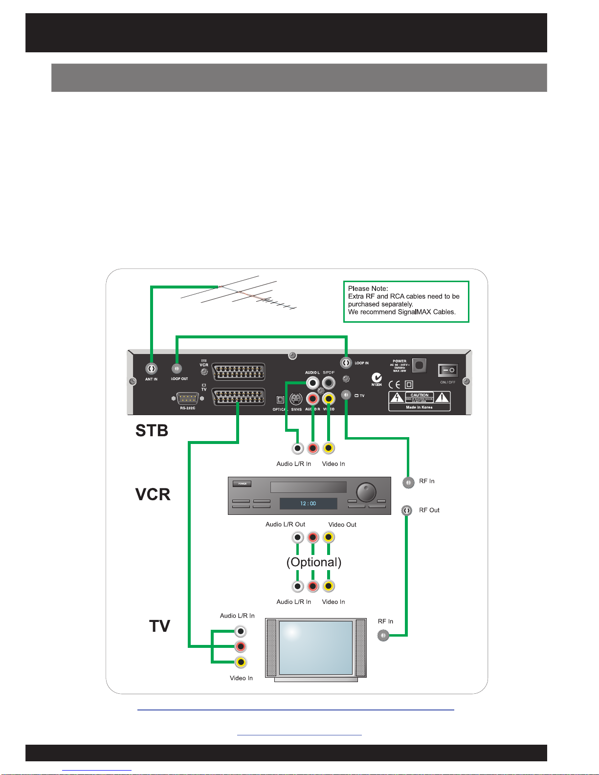
Installation
Connecting DVD, STB, VCR, TV
- This setup is ideal for a TV Set that does not have multiple AV inputs. If your TV Set has
multiple AV inputs (AV 1, AV2, etc) use them as you will retain picture quality.
We recommend quality SignalMAX Cable and Flyleads.
www.signalmax.com.au
1717
For other installation tips, please visit the NextWave Digital web site:
www.nextwave-digital.com
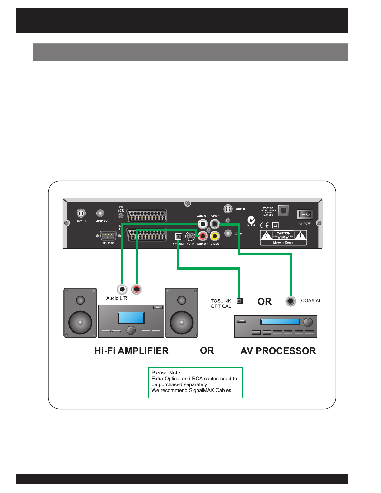
Connecting to a Hi-Fi system
Installation
- Connect a RCA stereo cable from the AUDIO OUT (L-R) sockets on the STB to the LINE
IN, AUX, SPARE or EXTRA input sockets on your HI-FI system.
- If available you can connect an RCA single coaxial cable from the SPDIF socket on the
STB to your AV Processor. Alternatively you can can connect a TOSLINK to TOSLINK
cable from the Optical connection from the STB to the AV Processor.
Please Note: If you use coaxial digital or the optical output from the STB, you will be able to hear Dolby Digital audio
through your Processor (When available from broadcasters).
18
The Menu System
Press the MENU button on your remote control and you will see the Main Menu on the screen.
The OK button always confirms your selection and pressing it will take you to the next step. You
can also go back to the previous step by pressing the MENU button. You can move upwards
and downwards by pressing the buttons.
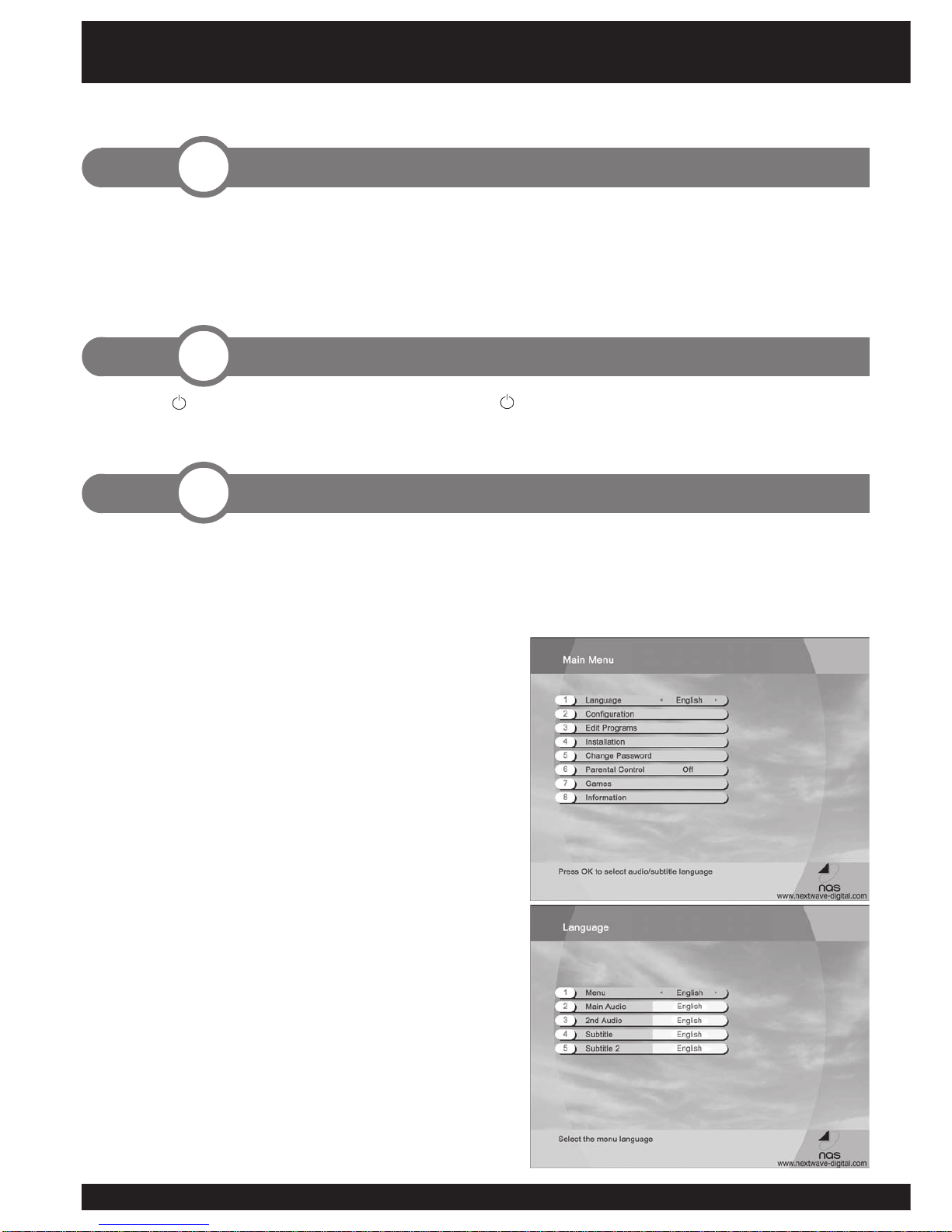
Selecting Menu Language
1. Press the MENU button on your remote control.
The Main Menu appears on the screen
2. Select ‘Language’ by using the buttons.
3. Select desired language by using the
buttons. The menu appears in the selected
language.
Selecting Audio Language
1. Press the MENU button on your remote control.
2. Select ‘Language’ by using the buttons
and press OK.
The Language menu appears on the screen.
3. Select ‘Main Audio’ by using the buttons.
4. You can select your preferred language as a
main audio language by using the buttons.
You can also select the alternative audio language
and subtitle language in this menu.
The following section contains all the steps necessary when first installing and using the receiver.
1. Connect the coaxial cable from the VHF/UHF antenna to the AERIAL socket on the rear
panel of the STB.
2. Connect the SCART or RCA leads between the input SCART or RCA socket on the TV and
the TV SCART or RCA sockets on the rear of the STB.
Press the button on the remote control or the button at the front of the STB set.
Please Note: On Standby mode the current time will be displayed.
Step. Basic Presetting
3
Step. Switching on the STB
2
Step. Installation
1
Getting Started
1919
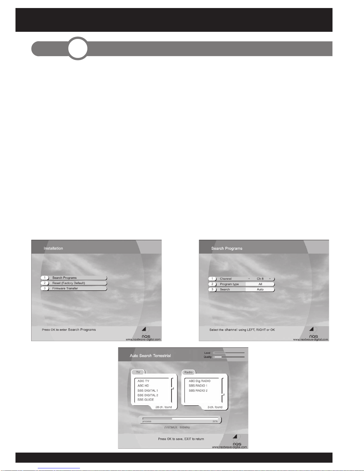
1. Press the MENU button on your remote control.
2. Select ‘Installation’ by using the buttons and press OK. And you will
be asked to enter your password. The password is preset to 0000. And the
Installation menu appears on the screen.
3. Select ‘Search Programs’ by using the buttons and press OK. And the
channel search menu appears on the screen.
4. Select ‘Channel’ using the buttons.
5. Select ‘Program Type’ using the buttons.
6. Select ‘Search’ using the buttons. And select the scan type using the
buttons. Press OK.
9. You can watch the search progress on the screen.
10. After scanning press OK to save or EXIT to cancel.
Step. Channel Searching
4
Getting Started

20
1. Press OK to access the TV Channel List while viewing programs.
2. Select channel by pressing the buttons. If the list contains a large number of
channels, you can change one page at a time by using the buttons.
3. Press OK to view selected channel.
Closed Caption
indicator
Sound On/Off Teletext indicator
Timer On/Off Radio enabled/
disabled
Pause enabled
Indicator Icons:
Step. Watching TV
5
Getting Started
3. Press the EXIT button to leave the Channel List.
4. Press the i button to get program information. Press the i button again to hide this information.
Table of contents
Other NextWave Digital TV Receiver manuals


