Nexus NX Compass User manual

Installation and Operation Manual
NX Compass
English

NX Compass Pack English
1

English NX Compass Pack
2
Edition: Mar 2012
This manual is written for NX Compass Instrument 1.00

NX Compass Pack English
3
1!Part specification .............................................................................................. 4!
2!Installation ......................................................................................................... 6!
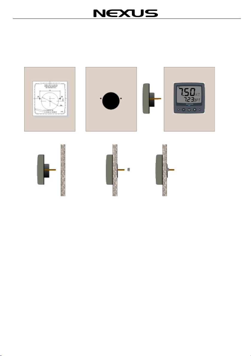
2.1!Installing the instrument.............................................................................................................. 7!
3!Installation ......................................................................................................... 8!
3.1!Location of the NX Compass ...................................................................................................... 8!
3.2!Check the location: ..................................................................................................................... 8!
4!Electrical installation ...................................................................................... 10!
4.1!Connect a stand alone Compass.............................................................................................. 10!
4.2!Connect In a NX system ........................................................................................................... 11!
4.3!NMEA and Push button connection.......................................................................................... 11!
4.4!Sealing the instruments ............................................................................................................ 12!
5!First start ......................................................................................................... 13!
5.1!Initialising the instrument .......................................................................................................... 13!
5.2!How to use the push buttons of the Wind instrument ............................................................... 14!
5.3!Main function ............................................................................................................................ 15!
5.4!Analogue function ..................................................................................................................... 15!
5.5!Sub-functions............................................................................................................................ 15!
5.5.1!Steer function[STR]................................................................................. 15!
5.5.2!Boat Speed [BSP] ................................................................................... 15!
5.5.3!Velocity Made Good (VMG) .................................................................... 15!
5.5.1!Geographic (True) Wind direction (TWD) ............................................... 16!
5.5.1!Steer mode ............................................................................................. 16!
5.5.2!Start up mode ......................................................................................... 16!
6!Calibration and setup of the Compass instrument...................................... 16!
6.1!Set damping for heading........................................................................................................... 16!
6.2!Select damping for BSP, VMG, TWD or STR........................................................................... 17!
6.1!Select unit for BSP and VMG ................................................................................................... 17!
6.2!Calibrate the compass sensor. ................................................................................................. 17!
7!Maintenance and fault finding ....................................................................... 18!
7.1!Maintenance ............................................................................................................................. 18!
7.2!Fault finding .............................................................................................................................. 18!
7.2.1!General fault finding................................................................................ 18!
7.2.2!Fault - action ........................................................................................... 19!
7.2.3!NMEA Out............................................................................................... 19!
8!Specifications.................................................................................................. 20!
8.1!Technical specifications Wind Instrument................................................................................. 20!
9!Warranty .......................................................................................................... 20!

English NX Compass Pack
4
1 Part specification
__________________________________________________________
Items delivered with the instrument
Qty Description Reference
1 NX Compass instrument 1
1 Instrument cover 2
1 Drill template for instrument 3
1 Installation and operating manual 4
2 Instrument mounting screws 5
2 Plastic nuts 5
1 Connection back cover 5
1 Silicon paste tube 5
1 Instrument connector 5
2 Plastic cable strap 5
5 Cable protectors, 0,25 mm (0.1 inch) 6
5 Cable protectors, 0,75 mm (0.3 inch) 6
Only in pack with Instrument and transducer
1 3m red power cable 7
1 3m black power cable 7
1 NX Compass transducer 8
1 Nexus Network cable, 10 m (30 ft) 9
3 Mounting screws for Compass transducer 10
Registering this product
Once you have checked that you have all the listed parts, please take time to fill in the
warranty document and return it to your national distributor.
By returning the warranty card, it will assist your distributor to give you prompt and
expert attention. Keep your proof of purchase. Your details will also be added to our
customer database so that you automatically receive new product catalogues when
they are released.
Warranty conditions see 9.

NX Compass Pack English
5

English NX Compass Pack
6
2 Installation
• The installation includes 5 major steps:
1. Read the installation and operation manual.
2. Plan where to install the Compass transducer and the instrument.
3. Run the cables.
4. Install the Compass transducer and the Instrument.
5. Learn the functions and calibrate your system.
Before you begin drilling ... think about how you can make the installation as neat
and simple as your boat will allow. Plan where to position the transducer and
instrument. Think about leaving space for additional instruments in the future.
•A few ”do nots” you should consider:
−Do not cut the cables too short. Allow extra cable length at the instrument
so it can be disconnected for inspection without having to disconnect all
attached cables.
−Do not place sealant behind the display. The instrument gasket eliminates
the need for sealant.
−Do not run cables in the bilge, where water can appear.
−Do not run cables close to fluorescent light sources, engine or radio
transmitting equipment to avoid electrical disturbances.
−Do not rush, take your time. A neat installation is easy to accomplish.
• The following material is needed:
Wire cutters and strippers.
Small and large Philips and a small flat head screw driver.
Hole saw to cut a hole for the instrument back of 63 mm (2½").
2.8mm drill for the Compass transducer mounting screws
5 mm (1/4") drill for the mounting holes.
Plastic cable ties
If you are doubtful about the installation, obtain the services of an experienced
technician.

NX Compass Pack English
7
2.1 Installing the instrument
•Place the adhesive drill template on the desired location for the instrument. Drill the
2 holes using a 5 mm (1/4") drill for the two pin bolts. Use a 63 mm (2½") hole saw
to machine the clearance hole for the instrument connection socket. Remove the
template.
•Screw the two pin bolts to the instrument
•Put the instrument in place
•Screw the two nuts from the back
Note! The two nuts must just be tightened by hand only
•Run the Nexus Network cable from the Compass transducer to the instrument.
•If you want to cut the Nexus Network cable to length, cut it in the instrument end.
Peel off about 35 mm (1.4") of the cable insulation. Remove about 6 mm (1/4") from
the 3 isolated wires (the 4th wire is an earth / screen). Attach the 4 cable protectors
to the wires using a pair of flat pliers.
•Connect the 4 cable protectors to the 4-pole jack plug as shown. Apply silicon
paste on all locations as shown.
Note: Must be done to avoid corrosion.

English NX Compass Pack
8
3 Installation
3.1 Location of the NX Compass
The transducer should be mounted horizontal or vertical (see pictures below). The
surface may be leaning ± 10 degrees from the horizontal or vertical plane.
It should be mounted perpendicular to the fore aft line (see picture on next page). Try to
mount the transducer reasonably well away from magnetic disturbances such as
objects containing iron, loudspeakers, window wipers etc. For safe distances, see page
11. The transducer does not have to be mounted in the centre of the boat. The
optimum position for the transducer is at the centre of gravity of the boat. At that
position there may be magnetic disturbances, therefore the transducer normally is
installed more forward. The transducer is normally mounted below deck but its water
resistant enclosure allows for outside mount, which is preferable for some steel boats.
3.2 Check the location:
If you have large disturbance sources or a steel boat we recommend to connect the
transducer, mount it temporary and check the readouts before mounting it permanently.
Horizontal mounting
Vertical mounting

NX Compass Pack English
9

English NX Compass Pack
10
4 Electrical installation
The transducer is connected to the Nexus Network.
After the electric installation you should check the readings on the instrument before
you proceed with the automatic compensation. If the readings are inaccurate with more
than 20º at any course, the transducer should be relocated.
4.1 Connect a stand alone Compass
C

NX Compass Pack English
11
4.2 Connect In a NX system
4.3 NMEA and Push button connection
C
SETSET
SPEED PLUS NAV WIND
C

English NX Compass Pack
12
4.4 Sealing the instruments
•Apply silicon paste to the instrument connection pins at the back of the instrument.
Press the jack plug onto the instrument pins. Press the cable in to the cable leads.
•Mount the connection back cover with the screw.

NX Compass Pack English
13
5 First start
5.1 Initialising the instrument
You will be asked to press SET (PrESkey) on the instruments the
very first time after installation. This will give the instrument a
logical ID number that belongs to your specific Nexus Network.
Press SET, on each installed instrument, one at the time.
Always wait for the text ‘Init OK’ to be displayed,
before you press SET on the next instrument!
The first unit ID number is 16, then 17 and so on in the order which
you press SET.
The example shows that the NX Compass
instrument has version no. 1.00 and ID
number 17

English NX Compass Pack
14
5.2 How to use the push buttons of the Wind instrument
CLEAR
A press on
CLEAR, clears
the digits.
MINUS
A press on
MINUS moves to
the next sub-
function.
In edit mode it
decreases to the
previous digit.
PLUS
A press on PLUS
moves to the
previous sub-
function.
In edit mode it
increases to the
next digit.
SET
A press on SET
unlocks a digit to
access edit
mode.
When unlocked,
the digits are
'active' (flashes)
and can be
edited by
pressing MINUS,
PLUS and PAGE
PAGE
A press on
PAGE toggles
the analog scale
The PAGE
button is also
used to move the
cursor when in
edit mode.
Heading
arrow
WIND ANGLE
HEADING
INFOTEXT
SUB-
FUNCTION

NX Compass Pack English
15
5.3 Main function
This function will always display Heading.
5.4 Analogue function
The analog scale is showing heading (5 degree / segment) or Steer function (2
degree/Segment). To toggle between these two, press PAGE.
5.5 Sub-functions
Select sub-function with PLUS or MINUS.
5.5.1 Steer function[STR]
The text [STR] (STeaR Function) and its value is displayed below.
To change the steer reference, press SET and select the new value with PLUS or
MINUS. A short press on Cwill set the current heading as steer reference.
5.5.2 Boat Speed [BSP]
The text [BSP] (Boat SPeed) and its value is displayed below.
The unit for [BSP] (Boat SPeed) may be selected between [KTS]
(KnoTS), [M/S] (Metres/s),[MPH] (Miles/h) or [KMH](Km/h).
5.5.3 Velocity Made Good (VMG)
The text [VMG] (Velocity Made Good)
is displayed with the actual boat speed
towards or against the Wind.
The water and wind speed information
are taken from the respective
transducers which are required to
provide VMG. The speed information
can be taken from the log transducer
or from Nexus Network. VMG = 0.0
knots when the true Wind angle is
perpendicular to the boat.
WIND

English NX Compass Pack
16
5.5.1Geographic (True) Wind direction (TWD)
Text [TWD] is displayed shortly, then is the abbreviation for
Wind directions displayed, [SSW], [NO], [WNW] etc. together
with the numerical direction below.
5.5.1Steer mode
The steer function will display the difference between the
reference course and the steered course.
To change the reference course, press SET. The current
heading is displayed, change with PLUS or MINUS and
press SET to lock the value in.
Note, an external push button may be connected to the back
of the instrument to automatically lock in the current
heading.
5.5.2 Start up mode
Your favourite function can be automatically displayed at power on.
Go the your favourite page and press PAGE and SET together and the display will start
flashing. Confirm that selection with a long press on SET.
6 Calibration and setup of the Compass instrument
To get the most out of your Nexus instrument, it is important to carefully calibrate the
instrument. The calibration values are stored in a non volatile memory.
6.1 Set damping for heading
Damping is how quickly the instrument shows the updated information. To access
settings for the Heading, press PLUS and SET together.
The selected damping for heading is displayed. Change the damping with PLUS or
MINUS and confirm with SET.
To select Magnetic heading instead of true, press PLUS and SET together. Press
PAGE and the trU or AG is displayed. Toggle between the two choices with PLUS or
MINUS and confirm with SET.

NX Compass Pack English
17
6.2 Select damping for BSP, VMG, TWD or STR
Go to the function you want to change the damping for. Press SET and MINUS
together. The current damping is displayed. Change with PLUS or MINUS and confirm
with SET.
6.1 Select unit for BSP and VMG
Go to the BSP or VMG function and press SET and MINUS together. Press PAGE and
the current unit is displayed. Select new unit with PLUS or MINUS and confirm with
SET.
Note, BSP and VMG will always use the same unit.
6.2 Calibrate the compass sensor.
In order to get the reading from the compass sensor correct, it has to be calibrated.
To enter the calibration mode, press SET for more than 2sec.
1. Set the mounting orientation of the compass sensor.
Press SET for more that 2 sec. Press PAGE one time and the text SET rEF is
displayed. Make sure the boat is levelled and press SET. The system will now
automatically detect if the compass is mounted horizontally or vertically.
2. Automatic deviation of the compass
Press SET for more that 2 sec. Press PAGE two times and the text DEV Aut is
displayed. Start turning the boat in a smooth turn in calm weather (making
sure you have room to make a comfortable 400 deg turn. Press SET and the
display will start to count down from 400. When you have reached zero, press
SET. Go back to normal display mode with a long press on SET.

English NX Compass Pack
18
7 Maintenance and fault finding
7.1 Maintenance
•To clean the instrument, use only mild soap solution and rinse
with water.
•Do not use detergents or high pressure washing equipment on
the instruments and transducers.
•Once a year, check all wiring and apply additional silicon
paste at each connection point.
•Always use the instrument cover for protection when not in
use.
•It is advisable to remove both instruments and transducers
and store them in a dry and room tempered place when not in
use for longer periods.
7.2 Fault finding
Before you contact your Nexus dealer, and to assist your dealer
to give you a better service, please check the following points and
make a list of:
• All connected instrument and transducers, including their
software version numbers.
• Software version numbers.
• Nexus Network data bus ID numbers for each instrument
(displayed at power up).
7.2.1 General fault finding
In most cases, the reason for faults in electronic equipment is the
installation or poor connections. Therefore, always first check that:
• Installation and connection is made per instructions for
instrument and transducers, (see 2).
• Screw terminals are carefully tightened.
• No corrosion on any connection points.
• No loose ends in the wires causing short cuts to adjacent
wires.
• Cables for damage, that no cables are squeezed or worn.
• Battery voltage is sufficient, should be at least 10V DC.
• The fuse is not blown and the circuit-breaker has not opened.
• The fuse is of the right type.
• Two instruments do not have the same ID number, (see 3).

NX Compass Pack English
19
7.2.2 Fault - action
1. Speed functions:
Check if the paddle wheel is spinning
Check if the transducer is connected the correct way
Irregular values: Check the speed damping (SEA)
2. Compass:
Is the compass calibrated
Irregular values: Check the compass damping (SEA)
7.2.3 NMEA Out
The NX Compass has a NMEA out port at the back of the
instrument. It will always send the following sentences:
1. HDG - Heading, Deviation and Variation
2. HDT - True Heading
3. *HDM - Heading Magnetic!
4. MWD - Wind Direction and Speed!
5. MWV - Wind Speed and Angle
6. MTW - Water Temperature
7. VHW - Water Speed and Heading!
8. VPW - Boat speed parallel to wind
9. *VWR - Apperent Wind angle and Speed!
10. *VWT - True Wind Angle and Speed
Table of contents
Other Nexus Compass manuals