NFT BusView User manual
BusView Installation Manual
with StudentView RFID Scanner
NFT-2600 Tracker | Revision Date 3/6/20
Confidential Page 1 3/6/2020

Table of Contents
Before Installing ...................................................... 3
Tools Needed For Installation.................................
3
GPS Fundamentals ................................................. 4
Checking the Contents of the Box ........................ 4
Installing and Mounting the GPS Unit................... 5
Cable Interface......................................................... 6
Main Harness Diagram ...................................... 6
RFID Cable Diagram.......................................... 7
Main Harness Details ........................................ 8
Relay Harness Details ....................................... 9
RFID Wiring Details ........................................... 9
Activating the NFT-2600 Unit ............................... 10
Troubleshooting Chart ........................................ 11
Items Needed for Install ....................................... 12
Confidential Page 2 3/6/2020

BEFORE INSTALLING
Prior to the installation process, thoroughly review and adhere to the following
items.
●Installation Manual
●Use only a Digital or Analog Voltmeter - DO NOT USE TEST LIGHT!
●Check for possible installation locations for the GPS unit prior to
permanent installation.
●ALWAYS LOOK BEFORE DRILLING. Make sure that the installation
process does not cause damage to any vehicle hose, electrical loom, or to
any part of the vehicle.
●Make note of the unit serial number prior to installation.
●Prior to working on any part of the dashboard (instrument cluster, center
console, glove box, etc.), remove the negative and positive terminal from
the battery to deactivate the sensors for the airbags. Refer to the Owner’s
Manual and to a Shop Manual for the vehicle for specific instructions in the
temporary deactivation process.
●DO NOT place objects, including communication equipment, in the area
over the airbag or near the airbag deployment area.
●Refer to the vehicle Owners Manual and to a Shop Manual for specific
information related to the electrical wiring, interior disassembly, and any
other mechanical aspects of the vehicle.
TOOLS NEEDED FOR INSTALLATION
●Metric and standard socket set
●Screwdriver set
●Side cutters, wire cutters
●Wire strippers
●Pliers
●Terminal crimpers
●Digital Multimeter
●Electrical tape
●Flashlight
Warning: It is highly recommended that a Digital Multimeter be used when
probing electrical systems in the vehicle to prevent damage to factory
components.
Confidential Page 3 3/6/2020

GPS FUNDAMENTALS
There is a minimum of 24 operational GPS satellites at all times. The satellites,
operated by the U.S. Air Force, orbit the earth every 12 hours. Each GPS
satellite transmits data that indicates its location and the current time. All GPS
satellites synchronize operations so that these repeating signals are transmitted
at the same instant. The signals, moving at the speed of light, arrive at a GPS
receiver at slightly different times due to the varying distances of satellites.
The distance to the GPS satellites can be determined by calculating the amount
of time it takes for their signals to reach the receiver. When the receiver
determines the distance to at least four GPS satellites, it can triangulate and
calculate its position in three dimensions.
To ensure the GPS unit receives enough satellite signals at acceptable signal
strength, it must be mounted so that it has a clear view of the sky. In hidden
locations, such as under the dash, a clear view can be challenging. In these
locations, it is important to keep any metal interference as far away as possible
from the top portion of the GPS unit so that the most accurate position can be
calculated.
While GPS data collection has improved in ease and speed, some obstacles
remain. Solid or dense objects can block GPS signals. Wet trees with heavy
branches and leaves can mask or attenuate GPS signals. Mountains and
buildings can block satellite transmission. Multipath signals can corrupt GPS
data. Multipath is a reflected signal from nearby objects. The resulting
propagation delay can affect measurement accuracy. GPS electronics
advancements have reduced the multipath threat but GPS field operators and
users should be aware of obvious multipath environments.
CHECKING THE CONTENTS OF THE BOX
The contents of the box containing the NFT-2600 are shown below:
Model
Contents
NFT-2600
1. NFT-2600 Unit
2. Cable Harness with Fuse
SV-RFID
1. RFID scanner
2. RAM mount
Confidential Page 4 3/6/2020

INSTALLING AND MOUNTING THE GPS UNIT
The best location for a stealth installation is beneath the top of the dash behind,
above or next to the instrument cluster. The GPS and GSM antennas are
internally located within the GPS unit. The unit must be mounted with the label
facing the sky. The GPS antenna is located under this label. The GPS unit will
work best if it has a clear view of the sky and as much of the horizon as possible
with no metal between it and the sky. Any metallic objects between the GPS unit
and the satellites will degrade the signal and reduce the overall performance. Try
to keep the device at least 12 inches away from audio devices such as vehicle
radio and speakers.
WARNING
The body of the car or any other metal structure can affect the
accuracy of the GPS signals and prevent normal operation. Location of the
GPS unit is critical to the operation.
The GPS unit can be installed in any type of vehicle. The unit should be mounted
so it will not be exposed to damage from people or objects. The GPS unit has tie
strap grips, use nylon tie straps to firmly mount the GPS unit.
Confidential Page 5 3/6/2020
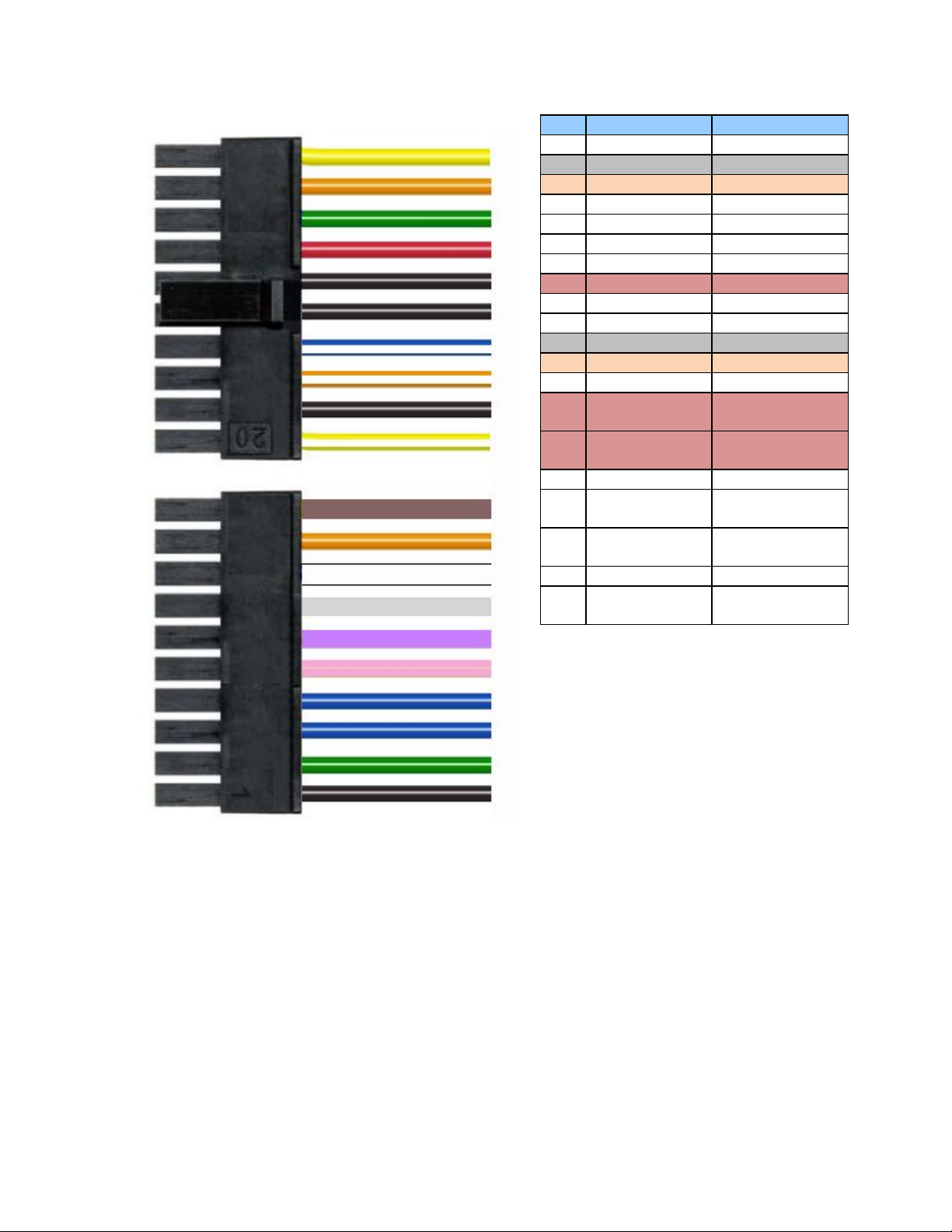
CABLE INTERFACE
Diagrams of the Cables are shown below:
Main Harness
Pin
Description
Lead Color
1
AUX 1
Black
2
Starter Disable
Green
3
Input 1*
Blue
4
AUX 1
Blue
5
Not Used
Pink
6
Not Used
Violet
7
Not Used
Grey
8
Ignition
White
9
AUX 1 /AUX 2
Orange
10
Not Used
Brown
11
RFID Buzzer
Yellow
12
Input 2*
Orange
13
AUX 1
Green
14
Primary Power
Input
Red
15
Primary
Ground
Black
16
RFID Ground
Black
17
RFID Data
White/Blue
Stripe
18
AUX 2
White/Orange
Stripe
19
AUX 2
Black
20
AUX 2
White/Yellow
Stripe
Confidential Page 6 3/6/2020

RFID Scanner Wiring
Description
Lead Color
Ground
Black
Buzzer
Brown
12v +
Blue
Data
White
Confidential Page 7 3/6/2020

Main Harness Connections in Detail
RED (+) Constant 12 volt Input
Locate the Red wire found on the 20-pin connector supplied with the GPS unit. The
red wire must be connected to a constant 12-volt source from the vehicle to power
the GPS unit. It's important that the 12 volt power source maintains 12 volts at all
times.
BLACK (-) Chassis Ground Input
Locate the Black wire found on the 20-pin connector supplied with the GPS unit. The
black wire must be connected to a solid chassis ground uninhibited by paint or
plastics. It is important that you do not use any floating grounds from the vehicle's
electrical system. Always connect the ground directly to the chassis body and secure
with a factory bolt or aftermarket screw insuring wire to metal connection.
WHITE (+) Ignition Input
Locate the white wire found on the 20-pin connector supplied with GPS unit. The
white wire must be connected to a true ignition 12-volt source from the vehicle. This
connection is used to monitor the engines on/off state. It's important that the
switched 12-volt source is (0) zero when the engine is off and switched 12 volts with
the engine cranking and running. WARNING: White wire must be connected for the
GPS receiver to work properly!
Blue - Warning Light Master
This input requires a transition from 0v to 12v. Some bus models have 12v when the
WLM is off and 0v when on and others are opposite. We will need to know which
option during the activation process.
White/Blue Stripe - RFID scanner interface
Located on pin 17, this wire will be connected to the white wire in the Rfid scanner
cable.
Black - RFID Ground
Located on pin 16, this wire will be connected to the black wire on the RFID
scanner cable.
Yellow- RFID Buzzer
Located on pin 11, this wire will be connected to the brown wire on the RFID
scanner cable.
Red- RFID Power
Cut the red wire that is connected to the plug labeled AUX 2, this wire will be
connected to the blue wire on the RFID scanner cable.
Confidential Page 8 3/6/2020

RFID Cable connections in Detail
White - RFID data
This wire will be connected to the white wire with blue stripe (pin 17) on the main
harness.
Black - RFID Ground
This wire will be connected to the black wire (pin 16) on the main harness.
Brown - RFID Buzzer
This wire will be connected to the yellow wire (pin 11) on the main harness.
Blue - RFID Power
This wire will be connected to the red wire that is part of AUX 2 on the main harness.
Confidential Page 9 3/6/2020

Activating the NFT-2600 Unit
Prior to the initial powering of the unit, move the vehicle outside, so that the GPS
receiver can receive signals from the GPS satellites.
Upon initial power up of the NFT-2600 the LEDs start flashing on the front side of
the unit to determine if the unit is powered on. If the LED is not flashing after 60
sec, check the power connections. The statuses of the LED’s are below.
Status LED Definitions
Orange LED Status
GSM/GPRS Cellular Communications
Green LED Status
GPS Communications
Blinking – Tracker on, searching for wireless signal
Blinking – GPS on, searching for satellite
signal
Patterned Blinking – Signal acquired, unit trying to
establish connection to the communication server
Solid – 2-way communication link with the
communication server established
Solid – GPS lock established
After the unit has been powered for 5 to 15 minutes, the unit will send in a
“power-up” message.
While waiting for the power-up message, collect the following information before
calling in (855-438-4771 option 2) for activating the unit:
Account ID
Vehicle Name
Device IMEI number
Please verify with tech support that the device has been activated and is working
properly before putting the unit back in service.
Confidential Page 10 3/6/2020
This manual suits for next models
1
Table of contents


