NHRC NHRC-10 User manual

NHRC
NHRCNHRC
NHRC-
--
-10
1010
10
User Guide
User GuideUser Guide
User Guide
Software Version: 1.0
User Guide Version: 2001-Mar-02

Copyright Notice
Copyright 1999, 2000, 2001 by NHRC LLC
This document contains proprietary information which is the confidential property of
NHRC LLC.
No part of this document may be used or reproduced, by any means, or for any
purpose, without the expressed written consent of NHRC LLC.
No part of this document should be considered to be specifications for the proper or
correct operation of the NHRC-10 Repeater Controller. In no way will NHRC LLC be
liable for direct or indirect damages to the controller or attached equipment.
Printed in the U.S.A.

Thank You!
Thank you for purchasing the NHRC-10 Repeater Controller. This controller has been
designed using the very latest state-of-the-art technology. Please review this manual
carefully before putting your controller into operation.
This manual represents a very large documentation effort. Your comments are
important to us. If you find an error or find any passages that are not clearly
understandable we would like to hear about it. Please send your comments to
Support for the controller is available by email or telephone. Please direct software-
promptly.
Questions of a more urgent nature can be answered by telephone support. Telephone
support is available Monday through Friday, from 6 PM until 10 PM, eastern time.


Table of Contents
Copyright 1999, 2000, 2001, NHRC LLC. All Rights Reserved. Page i
1. INTRODUCTION................................................................................................................................ 1
1.1 SENDING COMMANDS ..................................................................................................................... 2
1.2 ID MESSAGES ................................................................................................................................2
1.3 “UNLOCKED MODE” ...................................................................................................................... 3
2. ELECTRICAL CONNECTIONS ....................................................................................................... 4
2.1 INPUT AND OUTPUT SIGNAL LEVELS .............................................................................................. 4
2.2 DC POWER CONNECTOR ................................................................................................................ 5
2.3 REPEATER CONNECTOR ................................................................................................................. 6
2.4 LINK/REMOTE BASE CONNECTOR .................................................................................................. 7
2.5 CONTROL RECEIVER CONNECTOR.................................................................................................. 8
2.6 DELAY CONNECTORS ..................................................................................................................... 9
2.7 CI-V CONNECTOR........................................................................................................................ 10
2.8 OPTIONAL NHRC-10-DOUT EIGHT-PORT DIGITAL CONTROL OUTPUT BOARD .......................... 11
2.9 AUDIO LEVEL ADJUSTMENT......................................................................................................... 12
2.10 THE LED INDICATORS ................................................................................................................. 17
3. PROGRAMMING THE CONTROLLER....................................................................................... 18
3.1 QUICK START ............................................................................................................................... 18
3.2 INITIALIZING THE CONTROLLER.................................................................................................... 19
3.3 *0: UNLOCKED MODE CONTROL OPERATOR ACCESS .................................................................. 20
3.3.1 Set control operator switches.................................................................................................. 20
3.4 *1: SAVE SETUP ........................................................................................................................... 21
3.4.1 Save configuration setup......................................................................................................... 21
3.5 *2: PROGRAM COMMAND PREFIXES............................................................................................. 22
3.5.1 Set command prefix................................................................................................................. 23
3.6 *3: SET TIMERS ............................................................................................................................ 24
3.6.1 Program a timer...................................................................................................................... 25
3.7 *4: PROGRAM AUTOPATCH RESTRICTIONS................................................................................... 26
3.7.1 Assign an area code number to a bank................................................................................... 26
3.7.2 Set area code bank options ..................................................................................................... 27
3.7.3 Enable or disable an entire area code.................................................................................... 27
3.7.4 Enable or disable individual exchanges within an area code................................................. 28
3.7.5 Set Area Code Dialing Prefix.................................................................................................. 28
3.8 *5: PROGRAM AUTODIAL SLOTS .................................................................................................. 30
3.8.1 Program an emergency autodial number ............................................................................... 30
3.8.2 Clear an emergency autodial number..................................................................................... 30
3.8.3 Program a normal autodial number ....................................................................................... 31
3.8.4 Clear a normal autodial number ............................................................................................ 31
3.9 *6: (RESERVED FOR NHRC) ........................................................................................................ 32
3.10 *7: PROGRAM CW AND BEEP MESSAGES .................................................................................... 33
3.10.1 Program a CW ID............................................................................................................... 33
3.10.2 Program or play courtesy tones ......................................................................................... 34
3.11 *8: PLAY/RECORD VOICE TRACKS............................................................................................... 35
3.11.1 Play a message ................................................................................................................... 35
3.11.2 Record a message ............................................................................................................... 36
3.12 *9: (RESERVED FOR NHRC) ........................................................................................................ 36
3.13 **: RESET CONTROLLER .............................................................................................................. 36
4. CONTROL OPERATOR COMMANDS......................................................................................... 37
4.1 GROUP 0 SWITCHES: REPEATER CONTROL................................................................................... 38
4.2 GROUP 1 SWITCHES: MORE REPEATER CONTROL........................................................................ 39
4.3 GROUP 2 SWITCHES: VOICE ID AND TAIL MESSAGES .................................................................. 40
4.4 GROUP 3 SWITCHES: MISCELLANEOUS SETTINGS ........................................................................ 41
4.5 GROUP 4 SWITCHES: AUTOPATCH CONFIGURATION..................................................................... 43
4.6 GROUP 5 SWITCHES: LINK PORT CONFIGURATION ....................................................................... 45
4.7 GROUP 6 SWITCHES: DIGITAL OUTPUT PORT CONFIGURATION .................................................... 47
4.8 GROUP 7 SWITCHES: DIGITAL OUTPUT PORT CONTROL ............................................................... 48
4.9 GROUP 8 SWITCHES: PROGRAMMING WRITE PROTECT ................................................................ 49

Page ii Copyright 1999, 2000, 2001 NHRC LLC. All Rights Reserved.
4.10 GROUP 9 SWITCHES: CONTROL OPERATOR GROUP ACCESS ........................................................ 50
5. USER COMMANDS.......................................................................................................................... 51
5.1 AUTOPATCH ................................................................................................................................. 51
5.2 UNRESTRICTED AUTOPATCH ........................................................................................................ 52
5.3 AUTODIAL .................................................................................................................................... 53
5.4 EMERGENCY AUTODIAL ............................................................................................................... 54
5.5 PATCH HANG UP CODE ................................................................................................................ 54
5.6 DTMF ACCESS ............................................................................................................................ 55
5.7 RE-TRANSMIT DTMF................................................................................................................... 56
5.8 DTMF PAD TEST ......................................................................................................................... 57
5.9 REVERSE PATCH .......................................................................................................................... 58
5.10 AUDIO CHECK .............................................................................................................................. 59
5.11 VOICE MAILBOX .......................................................................................................................... 60
5.11.1 Play the voice mailbox headers .......................................................................................... 60
5.11.2 Play a specific message ...................................................................................................... 60
5.11.3 Record a message ............................................................................................................... 61
5.11.4 Delete the last message played........................................................................................... 61
5.11.5 Perform an audio check...................................................................................................... 61
5.12 REMOTE BASE.............................................................................................................................. 63
5.12.1 Select remote base operating mode .................................................................................... 63
5.12.2 Set or check transceiver mode ............................................................................................ 64
5.12.3 Set or check transceiver frequency ..................................................................................... 64
5.12.4 Select transceiver memory or VFO mode ........................................................................... 65
5.12.5 Select a transceiver memory channel ................................................................................. 65
5.12.6 Select transceiver split frequency operation....................................................................... 66
5.12.7 DTMF adjustment of operating frequency.......................................................................... 67
5.13 LOAD SAVED SETUP..................................................................................................................... 68
5.14 LITZ............................................................................................................................................. 69
6. APPENDICES .................................................................................................................................... 70
6.1 FACTORY DEFAULTS .................................................................................................................... 70
6.1.1 Default command prefixes table.............................................................................................. 70
6.1.2 Timer defaults table ................................................................................................................ 71
6.1.3 Courtesy tone component tones table ..................................................................................... 72
6.1.4 CW (“morse code”) character table ....................................................................................... 73
6.2 CONTROL OPERATOR CONTROLS ................................................................................................. 74
6.2.1 Control operator group 0 (repeater control) operations table ............................................... 74
6.2.2 Control operator group 1 (repeater control II) operations table............................................ 74
6.2.3 Control operator group 2 (voice and tail ID messages) operations table .............................. 75
6.2.4 Control operator group 3 (miscellaneous settings) operations table...................................... 75
6.2.5 Control operator group 4 (autopatch configuration) operations table .................................. 76
6.2.6 Control operator group 5 (link port configuration) operations table..................................... 76
6.2.7 Control operator group 6 (digital output port configuration) operations table ..................... 77
6.2.8 Control operator group 7 ( digital output port control) operations table .............................. 77
6.2.9 Control operator group 8 (programming write protect) operations table.............................. 78
6.2.10 Control operator group 9 (control operator group access) operations table .................... 78
6.3 SPEECH VOCABULARY TABLE...................................................................................................... 79
7. TERMINOLOGY AND ABBREVIATIONS................................................................................... 81
8. CIRCUIT BOARD ............................................................................................................................. 83
8.1 INTERCONNECTIONS..................................................................................................................... 83
9. SCHEMATICS................................................................................................................................... 85
10. PARTS LIST .................................................................................................................................. 91
11. NHRC LLC LIMITED WARRANTY ......................................................................................... 96

NHRC-10 User Guide
Copyright 1999, 2000, 2001, NHRC LLC. All Rights Reserved. Page 1
1. Introduction
The NHRC-10 Repeater Controller represents the current state-of-the-art in repeater
controller designs. It utilizes the latest available technology to provide maximum
functionality with the lowest number of parts. This results in very reliable operation.
The key features of the NHRC-10 are:
• Recording of four real speech ID messages and three real speech tail messages
yourself.
• Local language support using a custom recording capability.
• Six voice mailboxes, five saved operational setup memories, ten timers, and more
than 70 control operator functions.
• An audio test mode that records and plays back user's audio.
• A full-duplex autopatch with a database of 100 autodial numbers plus ten emergency
autodial slots.
• Support for up to four area codes with grant/deny access control to each exchange.
• Land line telephone access for "Reverse Patch" & controller administration.
• DTMF (“Touch Tone”) pad test.
• Dedicated DTMF receiver for telephone control and optional control receiver. (A
separate control receiver audio input with dedicated DTMF receiver is available.)
• Separate control receiver jack and DTMF receiver. DTMF receiver reverts to link
port when control receiver is not present.
• Connections for remote base, link radio, or slave repeater.
• Unique courtesy tones to indicate link/remote base status.
• Frequency-agile remote base supports remote control of ICOM IC-706MkIIG.
• LiTZ (Long Tone Zero)/911 message support; will play dedicated voice message in
response to LiTZ or 911 tones to tell user how to use emergency autodials, what
other repeater to use, etc.
• Transmitter fan control output automatically runs fan while transmitting and for a
programmable delay after.
• Real sine wave audio tones.
• DTMF "Carrier,” “Carrier and CTCSS,” and “Carrier or CTCSS" access modes.
• Granular security features that allow tailored control operator access.

NHRC-10 User Guide
Page 2 Copyright 1999, 2000, 2001 NHRC LLC. All Rights Reserved.
1.1 Sending commands
All of the controller’s commands are sent by DTMF (Touch-Tone) sequences that can
be received on the main repeater, over the telephone, the control receiver (if connected),
or the link radio (if the control receiver is not connected).
Commands received over the main repeater or link radio will be evaluated, and if correct,
executed, when either the DTMF inter-digit timer expires (2.0 seconds) or the CAS
(receiver unsquelched) signal drops; whichever comes first. This allows the controller to
be commanded even when a weak on-channel signal is holding the receiver’s squelch
open.
The telephone and control receiver do not have a CAS signal available. Commands
received from these sources will be evaluated when the DTMF inter-digit timer expires.
To send a command over the main repeater,
1. key your transmitter.
2. enter the DTMF command digits.
3. unkey the transmitter.
This will cause the command to be evaluated immediately.
If you pause for more than 2.0 seconds while sending a command, the command you
entered prior to the pause will be evaluated, the command buffer will be emptied, and
you can immediately enter another command.
When a command is successfully evaluated, the controller will send a response. Each
command’s possible responses are detailed with the command description.
In general, if you do not receive a command response, then the controller did not accept
your command.
1.2 ID Messages
The controller supports four voice ID messages and one CW ID.
The voice messages are comprised of:
• an “initial” ID message, that plays when the controller has been idle for a period
longer than the ID timer, and
• three “normal” ID messages.
Each of the normal ID messages can be individually enabled or disabled.
When more than one normal ID message is enabled, the enabled messages are played in
sequence; one each time the ID timer expires.
The CW ID will play when all the voice IDs are disabled, or when the repeater is keyed
during a voice ID message.

NHRC-10 User Guide
Copyright 1999, 2000, 2001, NHRC LLC. All Rights Reserved. Page 3
1.3 “Unlocked Mode”
All of the controller’s important programming information is protected by a special
password, the “unlock code.”
Programming the unlock code requires physical access to the controller to place a jumper
on the circuit board.
The unlock code cannot be re-programmed without physical access to the controller.
When the unlock code is successfully entered into the controller, the controller will say
“control access enabled,” and a special courtesy tone will be used to indicate the
controller is unlocked.
The controller can be locked by:
• sending the “#” command, or
• it will lock itself after two minutes of inactivity.
When the controller leaves the unlocked mode:
• it will say “control access disabled,” and
• the courtesy tone will revert to the normal tone for the controller’s current state.

NHRC-10 User Guide
Page 4 Copyright 1999, 2000, 2001 NHRC LLC. All Rights Reserved.
2. Electrical Connections
This section of the User Guide describes the electrical interfaces used to connect the
controller to:
• power,
• repeater and link radios,
• the control receiver, and
• NHRC-DAD digital audio delay boards.
It is intended for the repeater operator to use in the planning and installation of the NHRC-
10 Repeater Controller into a repeater system.
2.1 Input and Output Signal Levels
Control signals into the NHRC-10 are active-high signals. The repeater activity inputs
(CAS and CTCSS Decode) are buffered in the controller to allow the connection of
popular radios to the controller. Signal levels should be 0.0 to 0.5 volts for off, and 2.0
to 16.0 volts for on.
The controller’s PTT and FAN CONTROL outputs are “open-drain” connections to
power MOSFETs. These outputs are active-low, and when activated, will pull the
control signals to within a few ohms of ground. These outputs can sink 100 mA or so.
NHRC recommends that diodes be used to protect the MOSFETs from back-EMF if
these signals are used to drive relays.
Audio signals into the controller should be in the range of 0.2 to 2.0 volts peak-to-peak.
The controller’s transmit audio outputs are adjustable from about 0.1 volt to about 5
volts peak-to-peak.
The optional NHRC-10_DOUT digital output board provides eight additional digital
outputs. These outputs are “open-drain” connections to power MOSFETs. These
outputs are active-low, and when activated, will pull the control signals to within a few
ohms of ground. These outputs can sink 100 mA or so. NHRC recommends that diodes
be used to protect the MOSFETs from back-EMF if these signals are used to drive relays.

NHRC-10 User Guide
Copyright 1999, 2000, 2001, NHRC LLC. All Rights Reserved. Page 5
2.2 DC Power Connector
A mating power connector is supplied with the controller.
DC Power is supplied to the controller at connector “J7 12V,” with a 5.5 mm coaxial
power connector.
5.5 mm Coaxial Power plug
The inner connector (“Tip”) is positive
The outer barrel (“Sleeve”) is negative.
⇒
⇒⇒
⇒Caution: Reverse polarity could damage the controller, and will probably blow
the controller’s fuse.
J7 12V Connector Pin-out
Pin # Use
Sleeve “Outer Barrel” Ground
Tip “Inner Connector” +12 (13.8)

NHRC-10 User Guide
Page 6 Copyright 1999, 2000, 2001 NHRC LLC. All Rights Reserved.
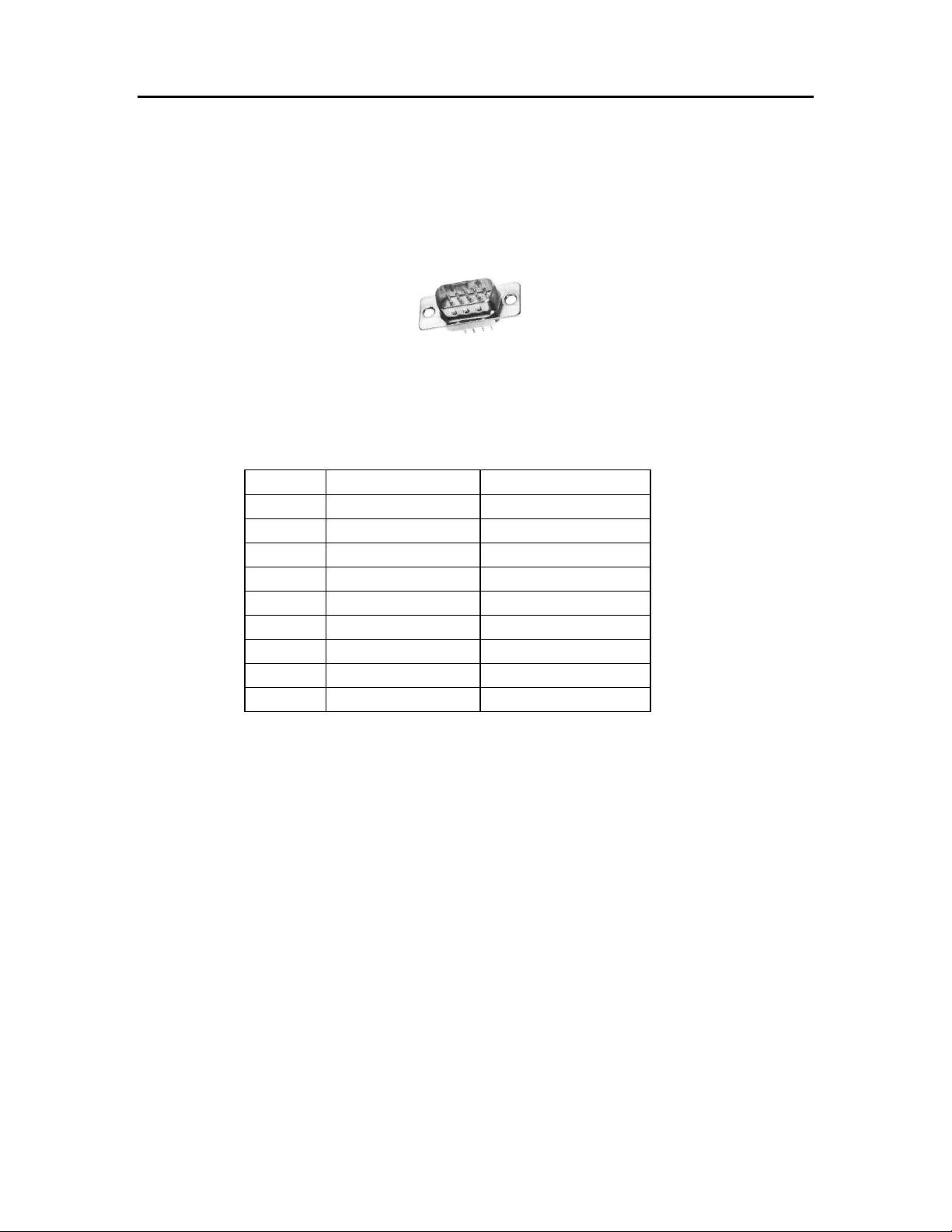
2.3 Repeater Connector
The main repeater is connected to the controller through the “J1 REPEATER” connector.
J1 is a Female DB9 Connector.
A Male DB9 Connector is included with the controller.
Male DB-9 Connector
J1 REPEATER Connector Pin-out
Pin # Use Comments
1 Ground
2 CTCSS Decode Active High
3 PTT Active Low
4 Transmit Audio From Controller
5 Receiver Audio To Controller
6 CTCSS Encode Future Option
7 CAS Active High
8 Ground
9 Fan Control Active Low
⇒
⇒⇒
⇒Note: The Fan Control output can be configured to either serve as a timed fan control
switch or as a digital output for other control applications. See Section 4.4 for information on
the operation of the fan control output.
NHRC-10 User Guide
Copyright 1999, 2000, 2001, NHRC LLC. All Rights Reserved. Page 7
2.4 Link/Remote Base Connector
The link/remote base radio(s) is connected to the controller through the “J2 REMOTE
BASE” connector.
J2 is a Female DB9 Connector.
A Male DB9 Connector is included with the controller.
Male DB-9 Connector
J2 REMOTE BASE Connector Pin-out
Pin # Use Comments
1 Ground
2 CTCSS Decode Active High
3 PTT Active Low
4 Transmit Audio From Controller
5 Receiver Audio To Controller
6 CTCSS Encode Future Option
7 CAS Active High
8 Ground
9 Ground

NHRC-10 User Guide
Page 8 Copyright 1999, 2000, 2001 NHRC LLC. All Rights Reserved.
2.5 Control Receiver Connector
The control receiver, if present, is connected to the “J6 CTRL RX” jack. J6 is a 3.5 mm
monophonic mini-phone jack.
3.5 mm mini-phone plug
If the control receiver is connected, then the control DTMF decoder will get the control
receiver audio.
If the control receiver is not connected, then the control DTMF decoder will get the
link/remote base audio.
⇒
⇒⇒
⇒Note: Consult section 4.2 for information about the link port control receiver
mode switch which may need to be set depending on your control receiver choice.
J6 CTRL RX Connector Pin-out
Pin # Use
Sleeve Ground
Tip Control Receiver Audio

NHRC-10 User Guide
Copyright 1999, 2000, 2001, NHRC LLC. All Rights Reserved. Page 9
2.6 Delay Connectors
The NHRC-10 supports the NHRC-DAD, a CODEC digital audio delay, to reduce squelch
crashes and fully mute DTMF tones.
Jacks “J3 MAIN DELAY” and “J4 RB DELAY” are provided on the controller to interface
NHRC-DADs.
Jacks J3 and J4 are .100” pin headers.
Note that if the DAD is not used, a shorting jumper must be installed between pins 2 and 3
of each of these jacks otherwise the controller will not pass audio.
J3 MAIN DELAY and J4 RB DELAY Connector Pin-out
Pin # Use
1 +12
2 Audio to DAD
3 Audio from DAD
4 Ground
See Section 4.4 for information about enabling a connected DAD.

NHRC-10 User Guide
Page 10 Copyright 1999, 2000, 2001 NHRC LLC. All Rights Reserved.
2.7 CI-V Connector
The NHRC-10 has an integrated CI-V interface which can be used to control IcomCI-V
compatible radios. The controller is intended to be mated to a IC-706 Mk II G.
The “J5 CI-V” connector allows the controller and radio to communicate. This allows
repeater users to operate the IC-706 Mk II Gas a frequency-agile remote base from 160
meters through 70 centimeters, with the exception of the 222 MHz band.
The CI-V control on the NHRC-10 should work with any modern Icomradio that
supports CI-V, with the exception of the IC-731and IC-735, which use an incompatible
frequency control format. The radio's CI-V configuration should be set up as follows:
• "CI-V Address" 48H.
• "CI-V Baud" 9600.
• "CI-V Transceive" off.
• "CI-V 731" off.
CI-V interconnection requires a shielded patch cord with 3.5 mm mini-phone plugs on each
end. One end connects to the "J5 CI-V" jack on the NHRC-10, the other end connects to
the CI-V jack on the Icomtransceiver.
3.5 mm mini-phone plug
J5 CI-V Connector Pin-out
Pin # Use
Sleeve Ground
Tip CI-V Data

NHRC-10 User Guide
Copyright 1999, 2000, 2001, NHRC LLC. All Rights Reserved. Page 11
2.8 Optional NHRC-10-DOUT Eight-Port Digital Control Output Board
The NHRC-10 can be equipped with the optional NHRC-10-DOUT eight-port digital
control output board. The NHRC-10-DOUT allows the NHRC-10 repeater controller to
control up to eight external loads. These outputs can be used to select power amplifiers,
disable voter channels, etc.
The NHRC-10-DOUT outputs are “open-drain” connections to power MOSFETs. These
outputs are active-low, and when activated, will pull the control signals to within a few
ohms of ground. These outputs can sink 100 mA or so. NHRC recommends that diodes be
used to protect the MOSFETs from back-EMF if these signals are used to drive relays.
⇒
⇒⇒
⇒Note: See Sections 4.7 and 4.8 for information on the configuration and operation
of the NHRC-10-DOUT.
⇒
⇒⇒
⇒Note: See Section 2.3 for information about the NHRC-10s built-in digital
output/fan control output.

NHRC-10 User Guide
Page 12 Copyright 1999, 2000, 2001 NHRC LLC. All Rights Reserved.
2.9 Audio Level Adjustment
Description of Audio Processing:
The NHRC-10 uses analog switching and audio mixing to route audio from audio sources
to the transmitter ports, voice recorder and phone patch.
The controller has two internal mix busses that supply audio to the various outputs. The
transmitter mix bus supplies audio to the main and remote base transmitters. The phone
mix bus supplies audio to the telephone line. Each mix bus has a variety of audio sources.
Each audio path through the controller is described in detail below.
The main receiver’s audio is passed into the controller through potentiometer VR5, and
then buffered through audio amplifier U1A for impedance isolation and equalization. This
amplifier can be set up to provide flat audio response or 6 dB/octave de-emphasis with a
roll-off of approximately 250 Hz, allowing the use of discriminator audio. The buffered
audio is then passed to touch-tone decoder U12, and through connector J3 to the optional
digital audio delay board for squelch tail elimination. If the digital audio delay is not
present, J3 pins 2 and 3 must be jumpered to allow audio to continue to pass through the
controller. After the digital audio delay connector, the main receiver audio is gated
through analog switch U3A. The gated audio is supplied to the transmitter mix bus via ,
potentiometer VR7, the phone mix bus via potentiometer VR9, and into the digital voice
recorder (DVR) chip via potentiometer VR11.
The remote base receiver’s audio is passed into the controller through potentiometerVR1,
and then buffered and equalized through audio amplifier U1D, identically to the main
receiver audio. The buffered audio is presented to J4 for the remote base receiver’s
optional digital audio delay board. If the digital audio delay is not present, J4 pins 2 and 3
must be jumpered to allow audio to continue to pass through the controller. Remote base
audio is gated through analog switch U3B, directly onto the transmitter mix bus.
Flat or de-emphasized audio on the main and remote base ports is simply selected by
moving the shorting jumpers from (N) normal position to (D) de-emphasized position.
Note if the jumper is completely removed the audio processing circuit will provide
approximately a 10X audio gain with flat response.
DTMF and courtesy tones are generated by tone generator U14, buffered by amplifier
U2A, and provided to the phone mix bus at a fixed level. The buffered tones are also
provided to the transmitter mix bus through potentiometer VR6, buffer amplifier U1B, and
analog switch U3C.
DVR output is buffered by amplifier U2B and provided to the phone mix bus. The
buffered DVR output is also provided to the transmitter mix bus via potentiometer VR10,
and through amplifier U1B and analog switch U3C, which are shared with the DTMF and
courtesy tone generator.
Phone audio is provided to the transmitter audio mix bus through potentiometer VR2,
buffer amplifier U1C, and analog switch U3D.

NHRC-10 User Guide
Copyright 1999, 2000, 2001, NHRC LLC. All Rights Reserved. Page 13
The transmitter mix bus is provided to the main transmitter through buffer amplifier U4A,
with it’s level adjusted with potentiometer VR5. The transmitter mix bus is also provided
to the remote base transmitter through buffer amplifier U4D, with it’s level adjusted with
potentiometer VR3. The transmitter mix bus is available for monitoring at connector J10.
Care must be taken to use a high-impedance load on J10 so the mix bus is not excessively
loaded.
The phone mix bus is sent to the phone line through buffer amplifier U4B.
Control receiver audio enters the controller through jack J8. If nothing is connected to J8,
then the remote base receiver audio is used for control receiver audio. Potentiometer VR4
sets the control receiver audio level into DTMF decoder U7.
Note: the DTMF, courtesy tone and speech levels into the phone line are fixed levels and
are not adjustable.
The J10 header is a test point for monitoring the audio levels on the transmitter mix bus.
The audio at this point is biased at approximately 6 VDC and should be AC-coupled
through a capacitor if it is to be used with an amplified speaker for monitoring levels. Care
should be taken not to load the transmitter mix bus with a low-impedance load on J10.
Description of Controls:
VR1 sets the remote base receiver audio input level to the remote base receiver audio
processing circuit.
VR2 sets the incoming telephone level to the transmitter audio mix bus. Use this control to
increase or decrease the audio level coming in from the phone line.
VR3 is the remote base transmitter master audio level adjustment Use this to adjust the
remote base transmitter deviation.
VR4 sets the control receiver DTMF decoder input level. This control sets the audio level
into the Control receiver DTMF decoder U7. Set this potentiometer for reliable
DTMF decode as indicated by LED D12 lighting each time a DTMF signal is
received on the control channel.
VR5 sets the main receiver’s input level into the audio processing stage of the controller.
This pot is used as an attenuator to reduce (if necessary) the amplitude of the
incoming audio signal from your repeater receiver. This control will affect the main
DTMF decoder (U12) and will also affect the level of the receiver into the phone line.
Adjust this pot for good receiver drive down the phone line. Use VR7 to reduce
receiver level into the transmitter mix bus if necessary. (Note: see VR9 for more
phone line drive information.)
VR6 is used to adjust the level of the courtesy tone and DTMF tones into the transmitter
audio mix bus. Use this control to increase or decrease the level of the courtesy tone
and DTMF tones into the transmitter audio mix bus. This adjustment has no effect on
the levels of the courtesy tone or DTMF tones into the phone line.

NHRC-10 User Guide
Page 14 Copyright 1999, 2000, 2001 NHRC LLC. All Rights Reserved.
VR7 is the processed audio output adjustment. This adjustment sets the main receiver
level into the transmitter mix bus.
VR8 is the main transmitter’s master audio adjustment. Use this to make adjustments to
the overall main transmitter deviation.
VR9 is the phone drive level. Use this adjustment to increase or decrease the incoming
receiver audio level into the phone line. This adjustment is affected by the setting of
VR5, the main RX level adjustment. If sufficient audio into the phone line is not
attainable, then it is likely that VR5 is set to low. Readjust VR5 for more input level.
VR10 is used to set the output of the DVR into the transmitter audio mix bus. Use this
control to increase or decrease the audio level coming out of the DVR into the
transmitter audio mix bus. This control has no effect on the speech level from the
DVR into the phone line.
VR11 is used to set the DVR input level for recording. Use this adjustment to increase or
decrease the record level into the DVR chip.
Audio Level Setup:
Recommended equipment:
• Signal generator or other method of generating a RF signal for the main receiver,
modulated with a 1 KHz tone at 3 KHz deviation.
• A deviation meter.
• A telephone line and phone.
• A Service Monitor is recommended for overall ease of alignment.
Procedure:
The reference level will be a 1 KHz tone at 3 KHz deviation
1. Prepare the controller for audio alignment by setting all potentiometers to the
midrange position, and properly configuring the input equalization (normal or de-
emphasized) by setting jumpers JP3 and JP1.
2. Transmit the reference tone through the repeater, and adjust VR5 for reasonable
transmitted deviation, about 3 KHz. The final adjustment of VR5 will occur later.
Turn off the reference signal.
3. Transmit some DTMF tones into the repeater, and adjust VR5 for reliable DTMF
decoding, as indicated by LED D10. (note VR-5 affects the rx audio into the phone
line and will be covered later in this section)
4. Initiate a phone patch. Adjust VR9 for solid receiver audio into the phone line. If
sufficient audio drive cannot be obtained at the maximum setting of VR9, then adjust
Table of contents
Other NHRC Controllers manuals


