NI 5752 User manual

GETTING STARTED GUIDE
NI 5752/5752B
50 MS/s Digitizer Adapter Module
Note Before you begin, complete the software and hardware installation
instructions in your FlexRIO FPGA getting started guide or controller for FlexRIO
getting started guide.
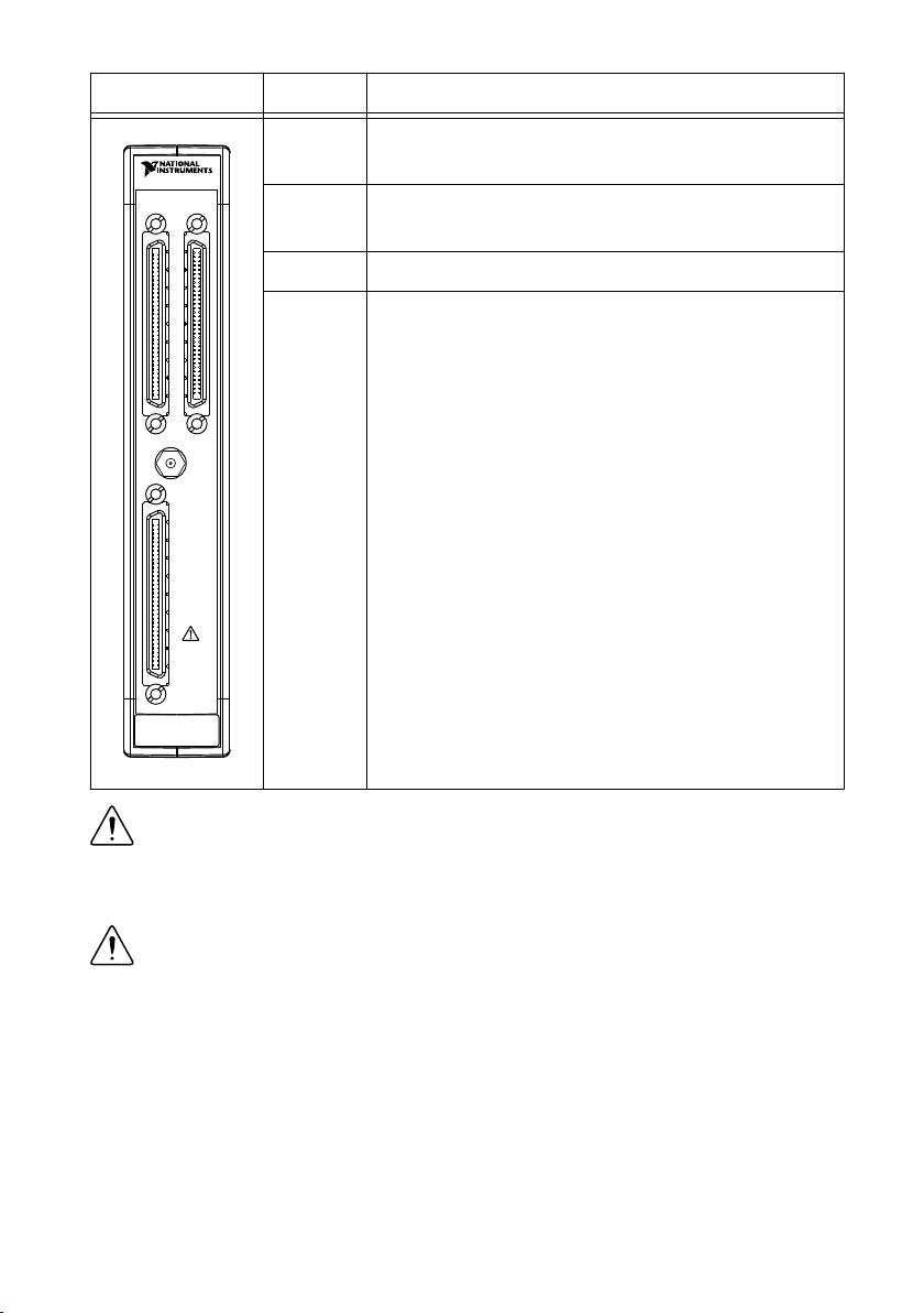
Caution Using the NI 5752/5752B in a manner not described in this document
may impair the protection the NI 5752/5752B provides.
The NI 5752/5752B is a 32-channel, 12-bit, 50 MS/s digitizer adapter module designed to
work in conjunction with FlexRIO FPGA modules and controllers for FlexRIO.
This document explains how to install and configure the NI 5752/5752B.
The NI 5752B variant is compatible with all FlexRIO FPGA modules and controllers for
FlexRIO. The NI 5752 variant is compatible with the NI PXI-795xR and NI PXIe-796xR
FPGA modules only.
Note NI 5752R refers to the combination of your NI 5752/5752B adapter module
and either a FlexRIO FPGA module or a controller for FlexRIO. NI 5752/5752B
refers to your adapter module only.
Contents
Electromagnetic Compatibility Guidelines...............................................................................2
FlexRIO Documentation........................................................................................................... 2
Verifying the System Requirements..........................................................................................4
Compatibility with FPGA Modules and Controllers for FlexRIO............................................4
Accessories................................................................................................................................4
Unpacking................................................................................................................................. 5
Preparing the Environment....................................................................................................... 6
Installing the NI 5752/5752B....................................................................................................6
Cables........................................................................................................................................6
Confirming that Measurement & Automation Explorer (MAX) Recognizes the Device........ 7
Front Panel and Connector Pinouts...........................................................................................7
Pinout and Signal Information.......................................................................................... 8
Block Diagram........................................................................................................................ 10
Component-Level Intellectual Property (CLIP)..................................................................... 12
NI 5752/5752B CLIP...................................................................................................... 12
Clocking.................................................................................................................................. 13
Worldwide Support and Services............................................................................................ 13
Where to Go Next................................................................................................................... 14

Electromagnetic Compatibility Guidelines
This product was tested and complies with the regulatory requirements and limits for
electromagnetic compatibility (EMC) stated in the product specifications. These requirements
and limits are designed to provide reasonable protection against harmful interference when the
product is operated in the intended operational electromagnetic environment.
This product is intended for use in industrial locations. However, harmful interference may
occur in some installations, when the product is connected to a peripheral device or test object,
or if the product is used in residential or commercial areas. To minimize interference with
radio and television reception and prevent unacceptable performance degradation, install and
use this product in strict accordance with the instructions in the product documentation.
Furthermore, any modifications to the product not expressly approved by National Instruments
could void your authority to operate it under your local regulatory rules.
Caution To ensure the specified EMC performance, operate this product only with
shielded cables and accessories.
Caution To ensure the specified EMC performance, you must install PXI EMC
Filler Panels, National Instruments part number 778700-01, in all open chassis slots.
You can order a kit of six single slot EMC Filler Panels directly from NI by visiting
ni.com.
Caution To ensure the specified EMC performance, the length of all I/O cables
must be no longer than 30 m (100 ft).
FlexRIO Documentation
Table 1. FlexRIO Documentation Locations and Descriptions
Document Location Description
Getting started guide
for your FlexRIO
FPGA module or
controller for FlexRIO
Available from the Start menu
and at ni.com/manuals.
Contains installation instructions
for your FlexRIO system.
Specifications
document for your
FlexRIO FPGA
module or controller
for FlexRIO
Available from the Start menu
and at ni.com/manuals.
Contains specifications for your
FlexRIO FPGA module or
controller for FlexRIO.
Getting started guide
for your adapter
module
Available from the Start menu
and at ni.com/manuals.
Contains signal information,
examples, and CLIP details for
your adapter module.
2| ni.com | NI 5752/5752B Getting Started Guide

Table 1. FlexRIO Documentation Locations and Descriptions (Continued)
Document Location Description
Specifications
document for your
adapter module
Available from the Start menu
and at ni.com/manuals.
Contains specifications for your
adapter module.
LabVIEW FPGA
Module Help
Embedded in LabVIEW Help
and at ni.com/manuals.
Contains information about the
basic functionality of the
LabVIEW FPGA Module.
Real-Time Module
Help
Embedded in LabVIEW Help
and at ni.com/manuals.
Contains information about real-
time programming concepts, step-
by-step instructions for using
LabVIEW with the Real-Time
Module, reference information
about Real-Time Module VIs and
functions, and information about
LabVIEW features on real-time
operating systems.
FlexRIO Help Available from the Start menu
and at ni.com/manuals.
Contains information about the
FPGA module front panel
connectors and I/O, controller for
FlexRIO front panel connectors
and I/O, programming
instructions, and adapter module
component-level IP (CLIP).
FlexRIO Adapter
Module Development
Kit User Manual
Available from the Start menu
at Start»All Programs»
National Instruments»NI
FlexRIO»NI FlexRIO
Adapter Module Development
Kit»Documentation.
Contains information about how
to create custom adapter modules
for use with FlexRIO FPGA
modules.
LabVIEW Examples Available in NI Example
Finder. In LabVIEW, click
Help»Find Examples»
Hardware Input and Output»
FlexRIO.
Contains examples of how to run
FPGA VIs and Host VIs on your
device.
NI 5752/5752B Getting Started Guide | © National Instruments | 3

Table 1. FlexRIO Documentation Locations and Descriptions (Continued)
Document Location Description
IPNet Located at ni.com/ipnet. Contains LabVIEW FPGA
functions and intellectual property
to share.
FlexRIO product page Located at ni.com/flexrio. Contains product information and
data sheets for FlexRIO devices.
Verifying the System Requirements
To use the NI 5752/5752B, your system must meet certain requirements. For more information
about minimum system requirements, recommended system, and supported application
development environments (ADEs), refer to the readme, which is available on the software
media or online at ni.com/updates.
Compatibility with FPGA Modules and
Controllers for FlexRIO
The NI 5752B variant is compatible with all FlexRIO FPGA modules and controllers for
FlexRIO; however, the NI 5752 variant is only compatible with NI PXI-795xR and
NI PXIe-796xR modules. The following table lists each adapter module's compatibility with
FlexRIO FPGA modules and controllers for FlexRIO.
Table 2. Adapter Module Compatibility
NI PXI-795xR NI PXIe-796xR NI PXIe-797xR NI-793xR
NI 5752 Yes Yes No No
NI 5752B Yes Yes Yes Yes
Accessories
NI SMB-2147/2148 devices are shielded signal accessories for NI 5752/5752B adapter
modules. NI SMB-2147/2148 accessories provide easy connections to other devices for testing
and debugging. For more information about these accessories, refer to the
NI SMB-2145/2146/2147/2148 User Guide. The following figure shows a typical setup of the
NI 5752/5752B with the NI SMB-2147 and NI SMB-2148 signal accessories.
4| ni.com | NI 5752/5752B Getting Started Guide

Figure 1. NI 5752/5752B with NI SMB-2147 and NI SMB-2148 Signal Accessories
NI PXI-1042
SMB-2147
Analog Input Accessory AI 3
AI 7
AI 2
AI 6 AI5
AI 1 AI 0
AI 4
AI 11
AI 15 AI 14
AI 10
AI 13
AI 9
AI 12
AI 8
1
2
3
44
1. PXI Chassis with FlexRIO FPGA and adapter
module
2. NI SMB-2147
3. NI SMB-2148
4. SHC68-C68-D4 Cable Assemblies
Unpacking
Caution To prevent ESD from damaging the devices, ground yourself using a
grounding strap or by holding a grounded object, such as your computer chassis.
1. Touch the antistatic package to a metal part of the computer chassis.
2. Remove each module from the package and inspect it for loose components or any other
sign of damage.
Caution Never touch the exposed pins of connectors.
Note Do not install a device if it appears damaged in any way.
NI 5752/5752B Getting Started Guide | © National Instruments | 5

3. Unpack any other items and documentation from the kit.
Store the devices in the antistatic package when they are not in use.
Preparing the Environment
Ensure that the environment you are using the NI 5752/5752B in meets the following
specifications.
Operating temperature (IEC 60068-2-1,
IEC 60068-2-2)
0 °C to 55 °C
Operating humidity (IEC 60068-2-56) 10% to 90% RH, noncondensing
Pollution Degree 2
Maximum altitude 2,000 m at 25 °C ambient temperature
Indoor use only.
Note Refer to the NI 5752/5752B Specifications at ni.com/manuals for complete
specifications.
Caution Clean the hardware with a soft, nonmetallic brush. Make sure that the
hardware is completely dry and free from contaminants before returning it to
service.
Installing the NI 5752/5752B
Refer to the getting started guide for your FlexRIO FPGA module or Controller for FlexRIO
for instructions about how to install your FlexRIO system, including the NI 5752/5752B.
Cables
NI recommends using the following cables with the NI 5752/5752B.
Signal Cable Description Part Number
Analog SHC68-C68-D3 188143B-01
Digital SHC68-C68-D4 196275A-01
These cables connect directly to the analog and digital connector on the NI 5752/5752B.
6| ni.com | NI 5752/5752B Getting Started Guide

Confirming that Measurement & Automation
Explorer (MAX) Recognizes the Device
Use Measurement & Automation Explorer (MAX) to configure your NI hardware. MAX
informs other programs about which devices reside in the system and how they are configured.
MAX is automatically installed with FlexRIO Support.
1. Launch MAX by navigating to Start»All Programs»National Instruments»NI MAX or
by clicking the NI MAX desktop icon.
2. In the Configuration pane, double-click Devices and Interfaces to see the list of installed
devices. Installed devices appear under the name of their associated chassis.
3. (PXI and PXI Express devices only) Expand your Chassis tree item. MAX lists all
devices installed in the chassis. Your default device names may vary.
Note If you do not see your hardware listed, press <F5> to refresh the list of
installed devices. If the device is still not listed, power off the system, ensure
the device is correctly installed, and restart.
4. (Controllers for FlexRIO only) Your device appears under the Remote Devices section.
Front Panel and Connector Pinouts
The following figure shows the front panel connectors for the NI 5752/5752B.
NI 5752/5752B Getting Started Guide | © National Instruments | 7

Device Front Panel Connector Description
NI 5752
AI 0-15 AI 16-31
16 DO
2 DI
CLK
IN
AI 0-15 Analog input channels AI 0+/AI 0- through
AI 15+/AI 15-
AI 16-31 Analog input channels AI 16+/AI 16- through
AI 31+/AI 31-
CLK IN External Sample Clock input
DIO 0-15 Digital input and output terminals
Caution To avoid permanent damage to the NI 5752/5752B, disconnect all signals
connected to the NI 5752/5752B before powering down the module, and connect
signals only after the adapter module has been powered on by the FlexRIO FPGA
module or controller for FlexRIO.
Caution Connections that exceed any of the maximum ratings of any connector on
the NI 5752/5752B can damage the device and the chassis. NI is not liable for any
damage resulting from such connections.
Pinout and Signal Information
The following figure shows the pinout for the analog input VHDCI front panel connector.
8| ni.com | NI 5752/5752B Getting Started Guide

Figure 2. Analog Input CH 0–31 Pinout
68
67
66
65
64
63
62
61
60
59
58
57
56
55
54
53
52
51
50
49
48
47
46
45
44
43
42
41
40
39
38
37
36
35
34
33
32
31
30
29
28
27
26
25
24
23
22
21
20
19
18
17
16
15
14
13
12
11
10
9
8
7
6
5
4
3
2
1
1
2
3
4
5
6
7
8
9
10
11
12
13
14
15
16
17
18
19
20
21
22
23
24
25
26
27
28
29
30
31
32
33
34
AI GND
AI GND
AI 1+
AI 1–
AI GND
AI 3+
AI 3–
AI GND
AI 5+
AI 5–
AI GND
AI 7+
AI 7–
AI GND
AI 9+
AI 9–
AI GND
AI 11+
AI 11–
AI GND
AI 13+
AI 13–
AI GND
AI 15+
AI 15–
AI GND
AI GND
AI GND
AI GND
AI GND
RSVD
AI GND
AI 0+
AI 0–
AI GND
AI 2+
AI 2–
AI GND
AI 4+
AI 4–
AI GND
AI 6+
AI 6–
AI GND
AI 8+
AI 8–
AI GND
AI 10+
AI 10–
AI GND
AI 12+
AI 12–
AI GND
AI 14+
AI 14–
AI GND
AI GND
AI GND
AI GND
AI GND
AI GND
RSVD
RSVD
RSVD
RSVD
RSVD
RSVD
AI GND
AI GND
AI GND
AI GND
AI 31–
AI GND
AI 29–
AI GND
AI 31+
AI GND
AI 27–
AI 29+
AI GND
AI 25–
AI 27+
AI GND
AI 23–
AI 25+
AI GND
AI 21–
AI 21+
AI GND
AI 19–
AI 19+
AI GND
RSVD = Reserved
CONNECTOR 0
(AI 0-15)
TERMINAL 34
TERMINAL 68
TERMINAL 35
TERMINAL 1
TERMINAL 35
TERMINAL 1
TERMINAL 34
TERMINAL 68
CONNECTOR 1
(AI 16-31)
RSVD
RSVD
RSVD
RSVD
RSVD
RSVD
RSVD
AI GND
AI 17–
AI 17+
AI GND
RSVD
RSVD
AI GND
AI GND
AI GND
AI GND
AI GND
AI GND
AI 30–
AI 30+
AI GND
AI 28–
AI 26+
AI 26–
AI 28+
AI GND
AI GND
AI GND
AI GND
AI GND
AI 18–
AI 18+
AI GND
AI GND
AI 16–
AI 16+
AI 23+
AI 20–
AI 20+
AI 22–
AI 22+
AI 24+
AI 24–
35
36
37
38
39
40
41
42
43
44
45
46
47
48
49
50
51
52
53
54
55
56
57
58
59
60
61
62
63
64
65
66
67
68
The following figure shows the pinout for the digital input connector.
NI 5752/5752B Getting Started Guide | © National Instruments | 9

Figure 3. Digital Input Pinout
TERMINAL 34TERMINAL 68
TERMINAL 35 TERMINAL 1
68
67
66
65
64
63
62
61
60
59
58
57
56
55
54
53
52
51
50
49
48
47
46
45
44
43
42
41
40
39
38
37
36
35
34
33
32
31
30
29
28
27
26
25
24
23
22
21
20
19
18
17
16
15
14
13
12
11
10
9
8
7
6
5
4
3
2
1
RSVD = Reserved
D GND
D GND
D GND
D GND
DO 0
DO 2
DO 4
DO 6
DO 8
DO 10
DO 12
DO 14
DO 1
DO 3
DO 5
DO 7
DO 9
DO 11
DO 13
DO 15
D GND
D GND
D GND
D GND
D GND
D GND
D GND
D GND
D GND
D GND
D GND
D GND
D GND
D GND
D GND
D GND
D GND
D GND
D GND D GND
D GND
D GND
D GND
D GND
D GND
D GND
D GND
D GND
D GND
D GND
D GND
D GND
D GND
D GND
D GND
D GND
DI 0
D GND
D GND
DI 1
RSVD
RSVD
RSVD
RSVD
RSVD
RSVD
RSVD
RSVD
Block Diagram
The following figure shows the NI 5752/5752B block diagram and signal flow.
10 | ni.com | NI 5752/5752B Getting Started Guide

Figure 4. NI 5752 Block Diagram
I16
AI B8
AI B15
I16
I16
I16
AI C16
AI C23
I16
AI D24
AI D31
ForceInit
cSpiDevice
cSpiAddr
cSpiWrData
cSpiRxData
cSpiReadEn
cSpiWriteEn
I16
I16
I16
AI A0
AI A7
Analog
Connectors
Digital
Connector
External
Clock In
NI 5752 Adapter Module LabVIEW FPGA CLIP
Clock
Multiplexer
Deserializer
Deserializer
Deserializer
Deserializer
Data Clock
DI 0
DI 1
DO 0
AdcTgcStart
AdcRegisterReset
SampleClkSrcSelect
Sync Clock
(DSTARA)
50 MHz Internal
Oscillator
ADC
A
ADC
B
ADC
C
ADC
D
ADC
Control
SPI
Engine
(AI 0+, AI 0
–) ...
(AI 7+, AI 7
–)
(AI 8+, AI 8–) ...
(AI 15
+, AI 15–)
(AI 16
+, AI 16–) ...
(AI 23
+, AI 23
–)
(AI 24
+, AI 24–) ...
(AI 31
+, AI 31
–)
InitDone
PllUnlocked
ADCErrorA
ADCErrorB
ADCErrorC
ADCErrorD
DO 15
Div Bit Clock
DI 0
X 3
NI 5752/5752B Getting Started Guide | © National Instruments | 11

Component-Level Intellectual Property (CLIP)
The LabVIEW FPGA Module includes component-level intellectual property (CLIP) for HDL
IP integration. FlexRIO devices support two types of CLIP: user-defined and socketed.
•User-defined CLIP allows you to insert HDL IP into an FPGA target, enabling VHDL
code to communicate directly with an FPGA VI.
•Socketed CLIP provides the same IP integration of the user-defined CLIP, but it also
allows the CLIP to communicate directly with circuitry external to the FPGA. Adapter
module socketed CLIP allows your IP to communicate directly with both the FPGA VI
and the external adapter module connector interface.
The FlexRIO adapter module ships with socketed CLIP items that add module I/O to the
LabVIEW project.
NI 5752/5752B CLIP
The NI 5752/5752B ships with the following CLIP items:
1. NI 5752 IO Module—This CLIP provides access to thirty-two analog input channels,
sixteen digital output lines, and two digital input lines. This CLIP also contains a SPI
interface to program the ADC registers. In the NI 5752/5752B IO Module CLIP, each
Sample Clock cycle generates a sample from the analog input channels. The following
clock sources are available and are selectable using the SampleClkSrcSelect control.
• 50 MHz onboard oscillator
• DStarA through IOModSyncClock
• External clock through the front panel SMB connector
Only external sample clock rates from 25 MHz to 50 MHz are supported with this CLIP.
Each 12-bit sample is output to LabVIEW as an I16 data type. The 12-bit data is left-
justified and padded with 4 zeros in the LSBs. The data is clocked out of the CLIP on
Data Clock.
2. NI 5752 Multidevice Synchronization—This CLIP provides access to thirty-two analog
input channels, sixteen digital output lines and two digital input lines. This CLIP also
contains a SPI interface to program the ADC registers. For applications requiring
synchronization across multiple NI 5752/5752B modules, this CLIP is recommended. For
more details on multidevice synchronization, refer to KnowledgeBase 5AN9QBLY at
ni.com/support.
In the NI 5752/5752B Multidevice Synchronization CLIP, each Sample Clock cycle
generates a sample from the analog input channels. DStarA is the only Sample Clock that
is routed. Only Sample Clock rates from 25 MHz to 50 MHz are supported with this
CLIP. Each 12-bit sample is output to LabVIEW as an I16 data type. The 12-bit data is
12 | ni.com | NI 5752/5752B Getting Started Guide

left-justified and padded with 4 zeros in the LSBs. You must rout DStarA to the CLIP
from LabVIEW FPGA. The data is clocked out of the CLIP on Data Clock.
Related Information
Refer to the FlexRIO Help for more information about FlexRIO CLIP items, how to configure
the NI 5752/5752B with a socketed CLIP, and for a list of available socketed CLIP signals.
Clocking
The NI 5752/5752B clock source controls the sample rate and other timing functions on the
device. The following table contains information about the possible NI 5752/5752B clock
sources.
Table 3. Sample Clock Sources
Clock Notes Frequency
Range
50 MHz
onboard clock
— 25 MHz to
50 MHz
Sync Clock
(DStarA)
Sync Clock (DStarA) is only available on NI PXI
Express FlexRIO FPGA modules (such as the
NI PXIe-796xR). DStarA is not available on
NI-793xR controllers for FlexRIO or NI PXI FlexRIO
FPGA modules (such as the NI PXI-795xR). On PXI
Express modules, Sync Clock is driven by the DStarA
from the PXI/PXIe backplane.
If you change the frequency of Sync Clock (DStarA)
or CLK IN (when used as the Sample Clock), you
must assert Force Initialization.
CLK IN (front
panel SMB)
If you change the frequency of Sync Clock (DStarA)
or CLK IN (when used as the Sample Clock), you
must assert Force Initialization.
Related Information
For more information about clock sources, refer to the FlexRIO Help.
Worldwide Support and Services
The NI website is your complete resource for technical support. At ni.com/support, you have
access to everything from troubleshooting and application development self-help resources to
email and phone assistance from NI Application Engineers.
NI 5752/5752B Getting Started Guide | © National Instruments | 13

Visit ni.com/services for NI Factory Installation Services, repairs, extended warranty, and
other services.
Visit ni.com/register to register your NI product. Product registration facilitates technical
support and ensures that you receive important information updates from NI.
A Declaration of Conformity (DoC) is our claim of compliance with the Council of the
European Communities using the manufacturer’s declaration of conformity. This system
affords the user protection for electromagnetic compatibility (EMC) and product safety. You
can obtain the DoC for your product by visiting ni.com/certification. If your product supports
calibration, you can obtain the calibration certificate for your product at ni.com/calibration.
NI corporate headquarters is located at 11500 North Mopac Expressway, Austin, Texas,
78759-3504. NI also has offices located around the world. For telephone support in the United
States, create your service request at ni.com/support or dial 1 866 ASK MYNI (275 6964). For
telephone support outside the United States, visit the Worldwide Offices section of ni.com/
niglobal to access the branch office websites, which provide up-to-date contact information,
support phone numbers, email addresses, and current events.
Where to Go Next
Refer to the following figure for information about other product tasks and associated
resources for those tasks.
14 | ni.com | NI 5752/5752B Getting Started Guide

custom applications within
an application programming
interface (API).
about hardware features
or review device
specifications.
more about your products through ni.com.
the application development
environment (ADE)
for your application.
*This item is also installed with the driver software.
Support
ni.com/support
FlexRIO
ni.com/flexrio
Services
ni.com/services
Located at ni.com/manualsLocated at ni.com/gettingstarted Available from the Start menu
FlexRIO Help*
Getting Started
with LabVIEW
LabVIEW FPGA
Module Help
NI 5752/5752B
Specifications*
FlexRIO Module
Development Kit
User Manual
DISCOVER
CREATE
LEARNEXPLORE
NI 5752/5752B Getting Started Guide | © National Instruments | 15

Refer to the NI Trademarks and Logo Guidelines at ni.com/trademarks for information on NI trademarks. Other product and
company names mentioned herein are trademarks or trade names of their respective companies. For patents covering NI
products/technology, refer to the appropriate location: Help»Patents in your software, the patents.txt file on your media, or the
National Instruments Patent Notice at ni.com/patents. You can find information about end-user license agreements (EULAs)
and third-party legal notices in the readme file for your NI product. Refer to the Export Compliance Information at ni.com/
legal/export-compliance for the NI global trade compliance policy and how to obtain relevant HTS codes, ECCNs, and other
import/export data. NI MAKES NO EXPRESS OR IMPLIED WARRANTIES AS TO THE ACCURACY OF THE INFORMATION
CONTAINED HEREIN AND SHALL NOT BE LIABLE FOR ANY ERRORS. U.S. Government Customers: The data contained in
this manual was developed at private expense and is subject to the applicable limited rights and restricted data rights as set forth
in FAR 52.227-14, DFAR 252.227-7014, and DFAR 252.227-7015.
© 2015 National Instruments. All rights reserved.
374736A-01 Oct15
This manual suits for next models
1
Table of contents
Other NI Adapter manuals