NI C Series User manual

USER GUIDE AND SPECIFICATIONS
NI 9795 WSN C Series Gateway
This user guide describes how to use the NI 9795 Wireless Sensor
Network gateway and lists specifications. The NI 9795 combines
with NI WSN-32xx nodes to form a wireless sensor network.
Figure 1. NI 9795 WSN Gateway

NI 9795 User Guide and Specifications 2 ni.com
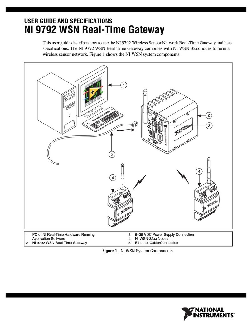
Figure 2. NI WSN System Components
Figure 2 shows the components of the NI WSN system. A NI WSN
system consists of one NI WSN gateway, up to 36 NI WSN-32xx
nodes per gateway, and multiple PCs or Programmable
Automation Controllers (PACs) to receive and analyze the
distributed sensor data. When you connect the NI WSN gateway,
1NIWSN-32xx Nodes
2 NI CompactRIO Chassis
3 NI 9795 WSN Gateway
4 PC or NI Real-Time Hardware
Running Application Software
5 Ethernet Network (not pictured)
1
1
2
4
3

© National Instruments Corp. 3 NI 9795 User Guide and Specifications
you can use a separate host PC running Windows, or a PAC running
NI LabVIEW Real-Time, to display measurement results, status
information, and to change the NI WSN gateway and
NI WSN-32xx node settings.
Safety Guidelines
Operate the NI 9795 only as described in these operating
instructions.
Hot Surface This icon denotes that the component may be
hot. Touching this component may result in bodily injury.
Caution Do not operate the NI WSN product in a manner
not specified in the user manual or operating instructions.
Product misuse can result in a hazard. You can
compromise the safety protection built into the product if
the product is damaged in any way. If the product is
damaged, return it to National Instruments for repair.
Caution If you need to clean a NI WSN product, wipe it
with a dry towel. The product must be completely dry and
free from contaminants before you return it to service.

NI 9795 User Guide and Specifications 4 ni.com
Safety Guidelines for Hazardous Locations
The NI 9795 is suitable for use in Class I, Division 2, Groups A, B,
C, D, T4 hazardous locations; Class I, Zone 2, AEx nA IIC T4 and
Ex nA IIC T4 hazardous locations; and nonhazardous locations
only. Follow these guidelines if you are installing the NI 9795 in a
potentially explosive environment. Not following these guidelines
may result in serious injury or death.
Safety Guidelines for Hazardous Locations
The NI 9795 is suitable for use in Class I, Division 2, Groups A, B,
C, D, T4 hazardous locations; Class I, Zone 2, AEx nC IIC T4 and
Ex nL IIC T4 hazardous locations; and nonhazardous locations
only. Follow these guidelines if you are installing the NI 9795 in a
potentially explosive environment. Not following these guidelines
may result in serious injury or death.
Caution Do not install or remove the gateway unless
power has been switched off or the area is known to be
nonhazardous.
Caution Substitution of components may impair
suitability for Class I, Division 2.

© National Instruments Corp. 5 NI 9795 User Guide and Specifications
Caution For Zone 2 applications, install the WSN system
in an enclosure rated to at least IP 54 as defined by
IEC 60529 and EN 60529.
Special Conditions for Hazardous Locations Use in Europe
The NI 9795 has been evaluated as Ex nA nL IIC T4 equipment
under DEMKO Certificate No. 07 ATEX 0626664X. Each gateway
is marked II 3G and is suitable for use in Zone 2 hazardous
locations, in ambient temperatures of –40 °C ≤Ta ≤70 °C.
Electromagnetic Compatibility Guidelines
This product was tested and complies with the regulatory
requirements and limits for electromagnetic compatibility (EMC)
as stated in the product specifications. These requirements and
limits are designed to provide reasonable protection against
harmful interference when the product is operated in its intended
operational electromagnetic environment.
This product is intended for use in industrial locations. There is no
guarantee that harmful interference will not occur in a particular
installation, when the product radio is operating in an environment,
or if the product is used in residential areas. To minimize the
potential for the product to cause interference to radio and

NI 9795 User Guide and Specifications 6 ni.com
television reception or to experience unacceptable performance
degradation, install and use this product in strict accordance with
the instructions in the product documentation.
Furthermore, any changes or modifications to the product not
expressly approved by National Instruments could void your
authority to operate it under your local regulatory rules.
The following statements contain important EMC information
needed before installing and using this product:
Caution This product is intended for use in industrial
locations. As a result, this product may cause interference
if used in residential areas. Such use must be avoided
unless the user takes special measures to reduce
electromagnetic emissions to prevent interference to the
reception of radio and television broadcasts.
Caution To ensure the specified EMC performance,
operate this product only with approved accessories.

© National Instruments Corp. 7 NI 9795 User Guide and Specifications
Software Overview
Note Refer to the NI WSN Readme, available on the
software installation disc included with your device or
from ni.com/drivers, for NI software application
version support. For information about which software
version supports your device, go to ni.com/info and
enter wsnsoftware.
The NI-WSN driver software includes NI Measurement and
Automation Explorer (MAX) as well as server and driver software
for easy integration into application software packages. These
software components manage the low-level communications and
hardware details, simplifying programmatic access to
I/O channels. The NI-WSN driver software is on the software
installation disc included with your NI 9795 gateway device. The
NI-WSN driver software is supported by Windows 7/Vista/XP and
contains the following components:
•NIMAX
• NI-WSN driver software

NI 9795 User Guide and Specifications 8 ni.com
What You Need To Get Started
For information about which software version supports your
device, go to ni.com/info and enter wsnsoftware.
• Host PC running Windows and NI software
• NI LabVIEW 2011 or later, and LabVIEW Real-Time 2011 or
later
• NI LabVIEW WSN Module (optional)
• NI-RIO 4.0 or later, included on software installation disc
included with your CompactRIO chassis
• NI-WSN 1.3 or later and NI Measurement & Automation
Explorer (MAX), on the software installation disc that shipped
with your gateway
• NI CompactRIO chassis with Scan Mode support. For more
information, visit ni.com/info and enter
rdsoftwareversion
Note Use only one NI 9795 WSN C Series Gateway per
NI CompactRIO chassis.
• NI 9795 WSN gateway

© National Instruments Corp. 9 NI 9795 User Guide and Specifications
•NIWSN-32xx node devices with an approved power supply or
four approved 1.5 V AA batteries for each node
• RJ45 Ethernet cable/Ethernet network
• NI CompactRIO approved power supply
• Related hardware and software documentation
Unpack the Device and Install the Antenna
Remove the device from the package and inspect the device.
Contact NI if the device appears damaged. Do not install a
damaged device.
Caution The device is static sensitive. Always properly
ground yourself and the equipment when handling or
connecting to the device.
To attach the antenna, align the antenna with the mount and screw
it on as shown in Figure 3.
Caution The antenna must be attached to the NI WSN
device in order for the NI WSN device to function
correctly.

NI 9795 User Guide and Specifications 10 ni.com
Figure 3. Attach Antenna to Device
Refer to the NI 9795 WSN Gateway Getting Started Guide for more
information about how to get started using your device.

NI 9795 User Guide and Specifications 12 ni.com
Using the NI 9795
Adding, Removing, and Replacing NI WSN-32xx
Devices
Use NI MAX to add and remove nodes to and from your
NI Wireless Sensor Network.You can add and remove
NI WSN-32xx devices while the system is operating and without
powering down the NI WSN system. NI WSN-32xx devices
already working in the system remain operational and accessible
on the network. Commands sent to a missing NI WSN-32xx device
return an error response, but the NI 9795 stores the commands and
applies the effects of the commands if a suitable replacement is
installed until the NI CompactRIO system is powercycled.
When you remove a NI WSN-32xx device and add a new one,
the NI 9795 first verifies that the replacement device is the same
node type as the one that was removed. If it is the same node type,
the NI 9795 device configures the replacement NI WSN-32xx
device with the previous device settings.
For more information, refer to Start»All Programs»National
Instruments»NI-WSN»Configuring WSN in MAX.

© National Instruments Corp. 13 NI 9795 User Guide and Specifications
NI Wireless Sensor Networks
The NI WSN system is built on an IEEE 802.15.4 wireless mesh
network. The 802.15.4 radio in each NI WSN device provides for
low-power communication of measurement data across a large
network of devices. The NI-WSN software builds on top of that to
provide network configuration and reliable communication from
the host PC or PAC to the NI WSN-32xx nodes.
Mesh Networking
The NI WSN system consists of two types of devices: gateways and
nodes. Gateways act as the network coordinator, in charge of node
connection, message buffering, and bridging from the 802.15.4
wireless network to the wired Ethernet network. Nodes primarily
function as end nodes in the network to collect data and control DIO
channels, but can also be programmed as routers to relay data from
other nodes back to the gateway and host PC or PAC. Router nodes
also collect data and control DIO, but require significantly more
power. Use NI MAX to configure nodes as end nodes or routers.
Figure 2 shows a typical NI Wireless Sensor Network.
The gateways and nodes work together to form a mesh network.
The gateway maintains a list of nodes (by serial number) that have
been authorized for network access. When a node powers up, it

NI 9795 User Guide and Specifications 14 ni.com
scans for available networks, locates either a gateway or router, and
attempts to join it. If the gateway has the node in its list, the node
joins the network, downloads the latest configuration from the
gateway, and begins its normal operation of acquiring
measurement data and controlling DIO.
Since each node joins a network instead of a particular router or
gateway, it can find a new path back to the gateway in the event that
the signal is lost or blocked to its existing network route. In this
way, the mesh network is inherently self-forming and self-healing.
However, this may also cause network throughput to decrease, as
there is no way to force a router or end node to join to a particular
device in the network. Each time a node joins through a router, the
overall throughput of that node is halved, because that the node
must hop to get its messages back to the gateway. Figure 5 shows
an example of one possible mesh configuration.

© National Instruments Corp. 15 NI 9795 User Guide and Specifications
Figure 5. Mesh Configuration Example
In this configuration, R1(a router) and R2(a router) both
communicate directly with the gateway. Measurements taken by
both devices can directly reach the gateway without having to hop
through another node. However, the configuration above does not
always mesh in the same way. Figure 6 shows another possible
configuration for the same network.
R
1
G
R
2

NI 9795 User Guide and Specifications 16 ni.com
Figure 6. Same Network Configuration Example
In this configuration, R1can still communicate with the gateway,
but R2 is now connected through R1. This means that all
measurements taken by R2must hop through R1before making it
back to the gateway. In addition, R1is now not only responsible for
sending its own measurement data, but also the R2 data. This
configuration is considered a worst-case 2-hop system, as R2and
R1both have the possibility of meshing through a router that is
connected to the gateway. National Instruments recommends
configuring your system for no more than three hops. Configuring
multiple nodes as routers and placing them within close proximity
R
1
G
R
2

© National Instruments Corp. 17 NI 9795 User Guide and Specifications
introduces the possibility that your system could mesh
inefficiently. Figure 7 shows how a system could mesh efficiently,
yet also have the possibility of meshing inefficiently.
Figure 7. Inefficient Versus Efficient Meshing
The network can be improved with two separate techniques:
1. Convert some routers to end nodes.
2. Set up the network to prevent the routers from being in range
of each other (spatially separated by distance, or introducing
objects that increase radio interference, such as buildings).
Another advantage of the mesh network is the ability to extend the
distance of the end measurement from the wired gateway. By
G
G
R1
R2
R
6
R1
R2
R3R4
R5
R6
R
3
R4
R
5

NI 9795 User Guide and Specifications 18 ni.com
placing mesh routers throughout the space where you wish to
acquire signals, you can expand the area and distance across which
measurement data can be acquired and sent. Refer to the
Specifications section for typical line of sight ranges for the
NI WSN devices. Figure 8 shows how a network can be set up to
cover greater distances.
Figure 8. Network Containing Distance Example
End Node Versus Router
Each NI WSN-32xx node can be configured as either an end node
or a router. NI WSN-32xx nodes are configured by default at the
factory in end node mode. You can change the mode of the node
using the NI-WSN software and NI MAX. One trade-off to
consider when configuring nodes is power consumption.
G
R1
R2
R3

© National Instruments Corp. 19 NI 9795 User Guide and Specifications
NI WSN-32xx nodes configured as end nodes are designed to be
run from battery power while routers are designed to use external
power at all times to send, receive, and buffer messages to and from
end nodes.
Data Transfer in the NI WSN Network
The NI WSN system is built on a low-power, reliable
IEEE 802.15.4 network. In order to save power and increase
reliability, this network delivers a maximum theoretical throughput
of 250 kbps. This correlates to a typical maximum rate of 1 sample
per second per node.
Measurements taken with NI WSN-32xx nodes are single point,
waveform, and string based depending on the hardware being used.
Nodes have an onboard buffer to handle lag in the network
conditions or reformation of a network. If the lag is greater than
several minutes or a node is shut down to power loss, the buffered
data is considered to be lost, meaning there is no way to retrieve
past data from the device.
Configuring Your NI WSN System
As discussed in the Mesh Networking section, creating a reliable
and efficient wireless sensor network requires an understanding of
the physical environment the network will reside in, as well as an

NI 9795 User Guide and Specifications 20 ni.com
understanding of the expected meshing configuration.
Additionally, the following consideration needs to be taken into
account: parent devices (routers and gateways) can only have a
maximum of eight end nodes connected to them at a given time.
This introduces the stranded node problem. The stranded node
problem exists when a node configured as an end node has the
possibility of not being able to join a device node. Figure 9 shows a
network consisting of one gateway, two routers, and nine end nodes.
Figure 9. Stranded Node Problem, Example 1
G
R2
R1
N
Nx 1
x 8
Other manuals for C Series
3
This manual suits for next models
1
Table of contents
Other NI Gateway manuals
Popular Gateway manuals by other brands

SEOWON INTECH
SEOWON INTECH SWC-5x00W series user manual

Scientific Atlanta
Scientific Atlanta Explorer 4250HD user guide

Trend Micro
Trend Micro InterScan Quick start card

Guest Internet
Guest Internet GIS-R6+ Quick setup guide

Zte
Zte ZXHN H198A user manual

EKE-Electronics
EKE-Electronics EKE-Trainnet MVB Technical manual

Crestron
Crestron infiNET EX CEN-RFGWX-EX Operations & installation guide

Ruckus Wireless
Ruckus Wireless MetroFlex MF2201 user guide

AMX
AMX NetLinx ZigBee Compatible Repe Operation/reference guide

eWON
eWON Flexy 205 quick start guide

tilgin
tilgin HG2330 series quick guide

ORiNG
ORiNG IMG-4312-MN Series Quick installation guide