EKE-Electronics EKE-Trainnet MVB User manual

MVB (EMD) 4TE
Multifunction
Vehicle Bus Module
Technical Manual

EKE-Electronics LTD
Piispanportti 7, FIN-02240 Espoo, FINLAND
Tel. +358 9 6130 3308
Fax +358 9 6130 3300
e-mail: electronics@eke.fi
Marketing and sales:
e-mail: electronics@eke.fi
TMS implementations, passenger train functions,
IEC 61131-3 type application programming
e-mail: electronics@eke.fi
Reports, testing, problem analysis
e-mail: [email protected]
The most recent information on EKE products and services is available at www.eke.com
Under copyright law no part of this document may be copied, reproduced or transferred electrically or manually, not even
partly, without prior written permission of EKE-Electronics LTD. This document is subject to change without notice.
EKE-Trainnet®is a registered trademark of EKE-Electronics LTD.
Copyright © 2008 EKE-Electronics LTD. All rights reserved.
EKE-Trainnet®MVB (EMD) Multifunction Vehicle Bus Module Technical Manual, version 1.04.

Contents
1: General information ...................................................................................................... 1
1.1 About this manual ..................................................................................................... 1
1.2 Safety considerations ................................................................................................ 1
1.3 Correct handling of the module ................................................................................. 2
1.4 Warning symbols used in this manual ....................................................................... 2
2: Overview of the MVB module....................................................................................... 3
2.1 Selected specifications .............................................................................................. 3
2.2 Module identification ................................................................................................. 4
2.3 Functionality diagram ................................................................................................ 5
2.4 MVB features ............................................................................................................ 5
2.4.1 Duplicated line ................................................................................................... 5
2.4.2 Medium Attachment Unit.................................................................................... 6
3: Installing the MVB into a rack ...................................................................................... 7
3.1 Before you begin ....................................................................................................... 7
3.1.1 Warnings............................................................................................................ 7
3.1.2 Preparations....................................................................................................... 8
3.2 Installation procedure ................................................................................................ 8
3.2.1 Placing the module in the rack........................................................................... 8
3.2.2 Checking the module ......................................................................................... 9
3.3 Problems in installation ........................................................................................... 10
4: On-board troubleshooting.......................................................................................... 11
4.1 Before you begin ..................................................................................................... 11
4.1.1 Warnings.......................................................................................................... 11
4.1.2 Preparations..................................................................................................... 12
4.2 Normal situation ...................................................................................................... 12
4.3 Error situations ........................................................................................................ 12
4.3.1 Yellow LED blinking or on ................................................................................ 13
4.3.2 Red LED on ..................................................................................................... 19
4.3.3 Red LED blinking ............................................................................................. 19
4.3.4 No LEDs on or glowing very faintly .................................................................. 20
5: Troubleshooting with software .................................................................................. 21
5.1 Finding the command you need .............................................................................. 21
5.2 MVB Configuration .................................................................................................. 22
5.3 Firmware loading ..................................................................................................... 22
5.4 Getting started with troubleshooting ........................................................................ 22
5.4.1 Automatic self-tests.......................................................................................... 23
5.4.2 Automatic self-tests.......................................................................................... 23
5.4.3 Note on commands.......................................................................................... 24

5.4.4 Structure of command sections ....................................................................... 25
5.5 HELP command ...................................................................................................... 26
5.6 Debugging commands ............................................................................................ 26
5.6.1 BA - Bus Administrator..................................................................................... 26
5.6.2 CHECK_LINE .................................................................................................. 27
5.6.3 CTRL (D).......................................................................................................... 27
5.6.4 GET_STAT - Get status................................................................................... 28
5.6.5 IN ..................................................................................................................... 30
5.6.6 MSGR - Message read (D) .............................................................................. 33
5.6.7 MSGS - Message send (D).............................................................................. 34
5.6.8 OUT - Output (D) ............................................................................................. 35
5.6.9 QUIT (D) .......................................................................................................... 35
5.6.10 REC - Reconfigure (D)................................................................................... 36
5.6.11 START (D) ..................................................................................................... 36
5.7 Memory commands ................................................................................................. 37
5.7.1 ADDR - Addressing mode................................................................................ 37
5.7.2 MEM - Memory switch ..................................................................................... 39
5.7.3 RM - Read Memory.......................................................................................... 39
5.7.4 RP - Read logical Port data ............................................................................. 40
5.7.5 SM - Set Memory (D) ...................................................................................... 41
5.7.6 SP - Set logical Port data (D).......................................................................... 41
5.7.7 TEST_EEPROM (D) ........................................................................................ 42
5.8 Software development commands .......................................................................... 43
5.8.1 AS - Active Slave ............................................................................................. 43
5.8.2 CS - Create Slave ............................................................................................ 44
5.8.3 MVB_MODE - MVB access mode selection (D) .............................................. 44
5.8.4 LOP - List of ports ............................................................................................ 45
5.8.5 LOS - List of Slaves ......................................................................................... 46
5.8.6 LPORT - Modify the logical port of an active slave .......................................... 46
5.8.7 RESET (D) ....................................................................................................... 47
5.8.8 VER.................................................................................................................. 47
Appendix A: Technical Specifications .......................................................................... 49
Appendix B: Diagrams .................................................................................................... 57

1
1: General information
This chapter includes general information about this manual (MVB EMD Multifunction
Vehicle Bus Module Technical Manual).
The following topics are covered in this chapter:
About this manual
Safety considerations
Correct handling of this module
Warning symbols used in this manual
1.1 About this manual
This is the technical manual for the EKE-Trainnet®MVB Multifunction Vehicle Bus
module.
In this manual, the abbreviation MVB always refers to the module, not to
the MVB bus. The module is referred to as “the MVB module” or "MVB".
When talking about the Multifunction Vehicle Bus, the entire name is used.
This manual includes instructions for the following tasks:
Installing the MVB into a rack
Troubleshooting the MVB on board
Troubleshooting the MVB with software
Note that this manual does not include instructions for the installation or maintenance
of the rack or its components. For these instructions, refer to the manual provided by
the rack manufacturer.
Also, this manual does not include information on other EKE-Trainnet®products. If you
need to check other modules than the MVB during troubleshooting, refer to the manual
of the corresponding module.
1.2 Safety considerations
The MVB is a low voltage device. In a normal situation, it presents no safety risk to the
user. However, in case of a severe train malfunction or wiring errors, there is a risk of
an electric shock through the bus cables.

General information
2
When you remove and handle a module, always hold it by the sides. Do not touch the
components.
Never disconnect the MVB from, or connect it to, a rack with active power, as this can
damage the MVB module or other modules in the system.
1.3 Correct handling of the module
Electrostatic discharge (ESD) can damage electronic circuits. EKE products are
protected against ESD. However, you run the risk of delivering electrostatic discharges
to the module whenever you handle it or any of its components. To avoid this risk, only
handle the MVB at a static-free workstation. If this is not possible, you must ground
yourself using a wrist strap and a resistive connection cord.
Remember to handle the module according to these instructions even
when you are removing a defective module and sending it to maintenance.
1.4 Warning symbols used in this manual
In this manual, situations that require caution (as specified above) are marked with
special warning symbols. The warning symbols appear in the beginning of the
appropriate chapter. The following symbols are used.
Figure 1.1: Electric shock warning symbol
Figure 1.2: General caution symbol
Figure 1.3: ESD warning symbol
Figure 1.4: Note symbol

3
2: Overview of the MVB
module
This chapter lists selected specifications of the EKE-Trainnet®MVB module and
highlights some of its features.
The following topics are covered in this chapter:
Selected specifications
Module identification
Functionality diagram
MVB features
2.1 Selected specifications
The EKE-Trainnet®MVB module is designed for train data transmission. It is an
interface between the VME Bus and devices attached to the Multifunction Vehicle Bus.
This section lists some technical specifications of the MVB module. For complete
technical specifications, see Appendix A.
Table 2.1: Selected specifications of the MVB module
Size of the printed circuit board 100 mm * 160 mm (Euro 1)
Width 4 TE
Height 3 U
Required free space in front of the module 75 mm
VME interface A24/D16, slave
MVB bus connectors Subminiature D9
Operating temperature –40 — +70 °C
Reliability (MBTF) greater than 1200 000 h
estimated from field data at 40 °C
ambient temperature

Overview of the MVB module
4
2.2 Module identification
Version and modification information appears on the board. The following pictures
show you where to find this information.
Figure 2.1: Location of version and modification information
The modification label shows the module modification. It is located above the back
connector of the module. The label includes letters, and the modification is indicated by
crossing out one. If nothing is crossed out, the modification is 00. If the letter A is
crossed out, the modification is A, and so on. This label gives the modification level of
the entire module, and the circuit board may have a different modification level,
indicated by numbers printed on the board’s modification field.

Overview of the MVB module
5
The board test label indicates that the board has gone through the required testing
cycle.
The serial number identifies the module. It is found on the back side of the front panel.
This is the serial number of the entire module, and the board has its own serial number.
The Module ID, located on the front panel handle, indicates an ID for this module. Again
note that the board has its own Board ID.
2.3 Functionality diagram
The following figure presents a general diagram of the MVB module functionality. For
a more detailed block diagram, see Appendix B.
Figure 2.1: General functionality diagram
2.4 MVB features
The MVB module is designed to ensure reliable data transmission on board a train. The
following sections present some MVB features intended for this purpose.
2.4.1 Duplicated line
To ensure uninterrupted functionality of the Multifunction Vehicle Bus, the bus is
duplicated: there are two lines (A and B) through which devices transmit data. In case
one of the lines is temporarily out of order, the other line can take over, and full
redundancy is ensured. This way, the flow of important data can continue without
interruption even in case of potential problems.
MVB MAU
VME bus
MVB
Configuration
MVB
Manager
(Z180)
PST Interface
Trainnet® Download
VME bus
Slave Logic
MVB line A
MVB line B
MVB MODULE

Overview of the MVB module
6
2.4.2 Medium Attachment Unit
The module has a fully IEC 61375-1 compliant redundant Multifunction Vehicle Bus
interface with EMD (Electrical Middle Distance) media, isolated by transformers.
The implementation of redundancy is based on MVBC01 ASIC and is subject to its
limitations.
EKE-Electronics LTD also manufactures versions of the MVB module, which support
OGF (Optical Glass Fibre) or ESD (Electrical Short Distance) media.

7
3: Installing the MVB into a
rack
This chapter includes instructions on how to install the EKE-Trainnet®MVB
Multifunction Vehicle Bus module into a rack.
The following topics are covered in this chapter:
Before you begin
Installation procedure
Potential problems
3.1 Before you begin
Read the following sections carefully before you start installing the MVB module.
3.1.1 Warnings
This section contains warnings you need to consider before and during the MVB
installation.
Do not turn on the rack power before you have finished the
installation.
Never connect the MVB to, or disconnect it from, a rack with active
power, as this can damage the MVB module or other modules in the
system. Always turn off the rack power first.
Electrostatic discharge can damage electronic circuits. When not handling
the module at a static free workstation, ground yourself using a wrist strap
and a resistive connection cord.

Installing the MVB into a rack
8
When handling the module, only touch the front panel. Do not touch the
board or any of the components on it.
Do not drop the module.
Make sure that the module or any of the components on it do not get wet.
Even when you are removing a defective module and sending it to
maintenance, handle the module according to these instructions.
3.1.2 Preparations
Before you start installing the MVB module to a rack, make the following preparations.
Make sure you have a Pozidrive Pz0 or Pz1 screwdriver to tighten the screws on
the module.
Check the shipping container to see that it is not damaged.
Take the module out of its shipping container carefully. The module is always
shipped in an ESD protective wrapping.
Check the module, especially the connector on the back, for any visible signs of
damage that may have occurred during shipment.
3.2 Installation procedure
The following sections include instructions for installing the MVB module into a rack.
3.2.1 Placing the module in the rack
The first step in the MVB installation is placing it in the rack. Do the following:
1Hold the module by the front plate.
2Place the module on the rails of the rack.
3Slide the module towards the back plane of the rack until it clicks into its place. Do
not use force.
4Tighten the two screws (slotted head collar screws) on the front panel.
5If there are other modules in the rack, make sure that the front plate of the MVB
module is at the same level with the other modules.
If the module does not fit into its place in the rack, see section 3.3 on page 10.
Installing the MVB into a rack
9
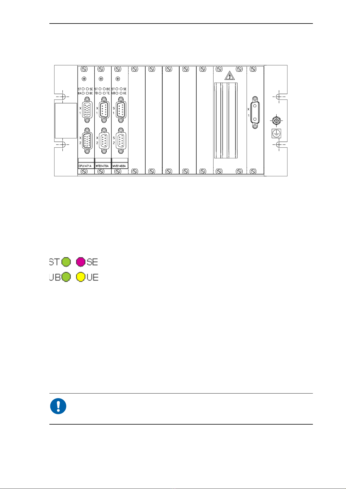
The following picture shows a sample rack with modules successfully installed. The
modules in the picture are just an example, and the picture is intended as illustration
only.
Figure 3.1: Modules installed in a rack, an example only
3.2.2 Checking the module
When you have successfully installed the module in the rack, the next step is to check
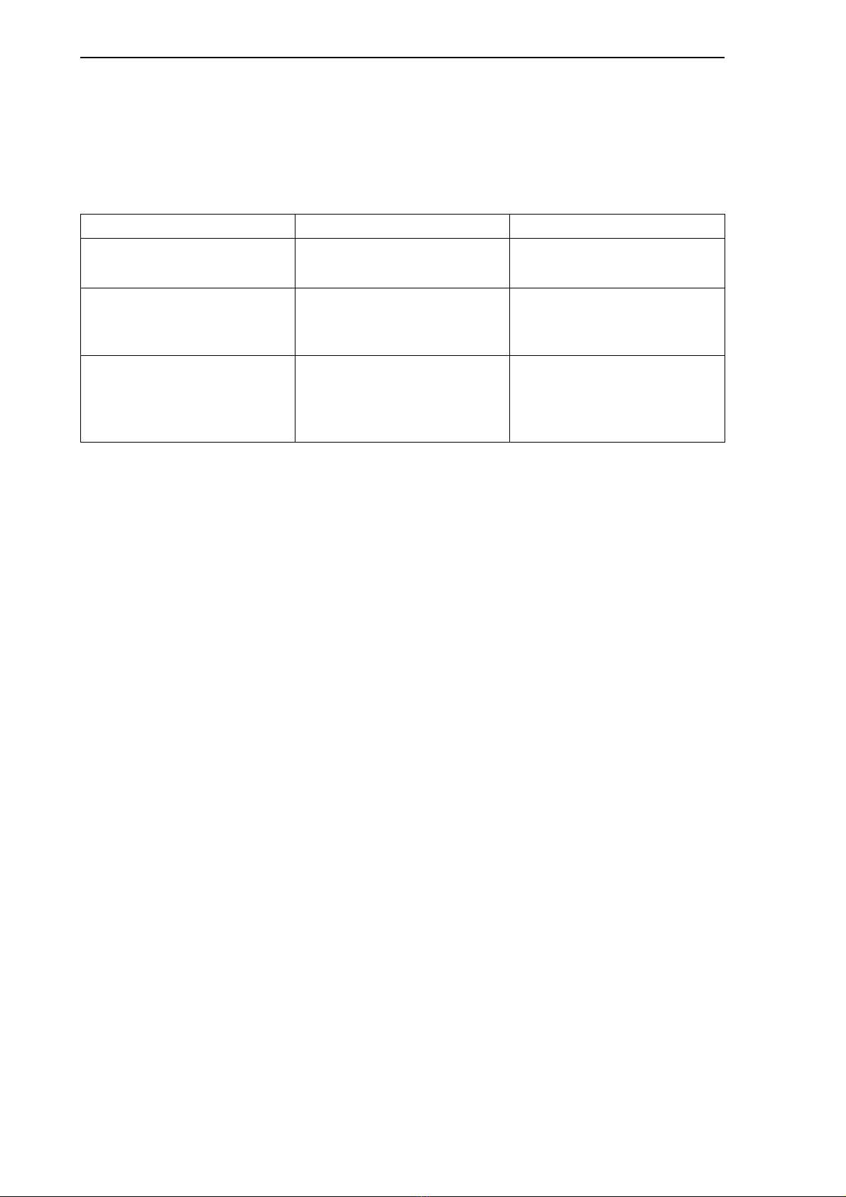
that the module works. You can do this by observing the LEDs. The following picture
shows the four LEDs on the module and their names.
Figure 3.2: MVB LEDs
To check the module, do the following:
1Turn on the rack power.
2Check that the green ST LED is on. Also, check that the red SE LED and yellow UE
LED are not on. This means that the module is OK.
3If the red SE LED and yellow UE LED are constantly on, the module is not OK. In
such a case, make sure you have placed the MVB module properly in the rack. If
these LEDs still remain on, turn off the rack power, loosen the screws on the module
front panel and pull the module carefully out of the rack.
During module start-up, the red and yellow LEDs are on for a moment and
then go off. This is part of the normal start-up procedure and does not
indicate an error.
If the module was not OK, see the following section.
Installing the MVB into a rack
10
3.3 Problems in installation
The following table lists some potential problems that can occur during the MVB
installation, as well as their causes, and actions you can take to solve the problem.
Table 3.1: Potential problems in the installation procedure
Problem Potential cause Action
The module does not fit into
the rack.
The connector pins of the
module are be damaged.
Replace the module with a
spare one.
Connector pins are OK, but
the module does not fit into
the rack.
The back plane of the rack is
damaged.
Refer to the documentation
provided by the rack
manufacturer.
You have installed the
module into the rack, but it is
not working: the red SE LED
and yellow UE LED are on.
The module is damaged. Replace the module with a
spare one.

11
4: On-board troubleshooting
This chapter includes instructions for troubleshooting the EKE-Trainnet®MVB module
on board a train.
The following topics are covered in this chapter:
Before you begin
—Warnings
—Preparations
Normal situation
Error situations
—Yellow LED blinking or on
—Red LED on
—Red LED blinking
—No LEDs on or glowing very faintly
4.1 Before you begin
Read the following sections carefully before you start troubleshooting the MVB module.
4.1.1 Warnings
This section contains warnings you need to consider before and during the
troubleshooting of the MVB.
Never disconnect the MVB from a rack with active power, as this can
damage the MVB module or other modules in the system.
Electrostatic discharge can damage electronic circuits. Always handle the
module at a static free workstation. If this is not possible, ground yourself
using a wrist strap and a resistive connection cord.
When you remove and handle the module, always hold it by the front panel
or sides. Do not touch the board or any of the components on it.
Remember to handle the module with care even when you are removing a
defective module and sending it to maintenance.

On-board troubleshooting
12
4.1.2 Preparations
You may need the following tools and devices:
A Pozidrive Pz0 or Pz1 screwdriver to loosen the screws on the module.
An oscilloscope
A multimeter
4.2 Normal situation
The front panel of the MVB contains four LEDs: two green, one red and one yellow.
You can detect the status of the MVB module by looking at the LEDs in the front panel.
The following picture shows the four LEDs on the module and their names.
Figure 4.1: MVB LEDs
When the LEDs are on, it means the following:
In a normal situation, the green ST LED is on and the green UB LED is blinking. If the
red SE LED or the yellow UE LED is on, there is an error situation. For troubleshooting,
see page 13 (Yellow LED blinking) and page 19 or page 19 (Red LED on/blinking).
During the module start-up, the red SE LED and yellow UE LED are on for
a moment and then go off. This is part of the normal start-up procedure and
does not indicate an error.
4.3 Error situations
If the Multifunction Vehicle Bus does not function normally, the problem can be either
in the MVB module or in the bus itself. If the problem is with the bus, you can only
troubleshoot it on board the train. If the problem is with the module, you need to remove
ST (green):
STATUS
Module hardware has started.
UB (green):
UNIT BUS
Principal activity of the module is OK; the module is transmitting data.
UE (yellow):
UNIT ERROR
Problems with the principal activity of the MVB module. This means that the
module has detected a network bus related error or a data transmission
error.
SE (red):
SYSTEM
ERROR
No principal activity in the MVB module. This means that the module is not
able to provide any kind of bus service.

On-board troubleshooting
13
the module from the rack, replace it with a spare one and send the defective module to
maintenance.
The following sections give you hints on analysing error situations and finding out
whether the problem is with the module or with the bus. The sections are arranged by
symptoms, in other words, by the problems you observe when checking the module or
browsing the Coach Computer.
The following table lists symptoms that are covered in this chapter.
Table 4.1: Symptoms for potential problems with the MVB module and the Multifunction
Vehicle Bus
4.3.1 Yellow LED blinking or on
If the yellow UE LED of the MVB module is blinking, there are sporadic transmission
errors in the Multifunction Vehicle Bus or the MVB has not received its configuration
from the Gateway CPU. If the yellow LED remains constantly on, there is a continuous
problem with one or more of the lines. You need to rule out the following causes for the
error situation:
Missing configuration
Defective module
Wrong connection or a loop connection or missing termination
Missing or defective device
Physical defect in connectors
Low signal level or missing signal
Defective termination
The following sections provide you with tips and instructions for solving these error
situations.
Missing configuration
This situation is most likely to occur if the system has been reset for some reason, and
the MVB has not re-received its configuration from the Gateway CPU. In this case, the
green ST LED is on, and the yellow UE LED is blinking. You should try resetting the
Coach Computer again. If the situation does not alter, there may be a fault with the
Gateway CPU or with the VME backplane.
Symptom To find out potential causes, see page
Yellow LED blinking or on 13
Red LED on 19
Red LED blinking 19
No LEDs on or LEDs glowing very faintly 20

On-board troubleshooting
14
Defective module
A transmission error can be caused by a defective module. All EKE-®modules have
passed a production test procedure and are thus guaranteed to function properly.
However, a module may be damaged during shipment or handling.
To find out whether the transmission error is caused by a defective module, do the
following:
1Disconnect connectors M1 and M2 from the MVB module and connect the
terminators in their place. The module is no longer connected to the bus.
2Check the green UB LED. It should be dimly lit when the terminators are connected.
(The yellow UE LED, too, remains on.)
3If the green ST LED is not lit or blinks only very dimly, the module is defective.
Remove the module from the rack and replace it with a spare one.
If the module was not defective, try resetting the Coach Computer - the problem could
be with the application software of some other module.
If the problem persists, continue with the troubleshooting tips presented in the following
sections.
Physical defect in connectors
A transmission error can be caused by a physical defect, such as oxidation, in the MVB
connectors or in the bus cable.
To find out whether the transmission error is caused by a physical error in connectors,
check the connectors visually. Also, if the terminators are in their place and the green
UB LED is not on, the cable connector is more than likely defective.
If there is no physical error in connectors, continue with the troubleshooting tips
presented in the following sections.
Wrong connection or a loop connection or missing termination
In this situation the yellow UE LED is on, and the green UB LED is blinking faintly. The
transmission error may result from a wrong connection or a loop connection. The
terminator modules might be missing, or in the wrong places, or the Multifunction
Vehicle Bus might have been connected into a loop. Visually check all connections and
terminations.
Missing or defective device
In this situation the yellow UE LED is on, and the green UB LED is either on or blinking
very rapidly. The module is not getting a response from all the ports in its configuration.
The MVB configuration may not match with the connected slave devices, or the slave
devices may be defective. Check all connections, terminations and devices, or
troubleshoot the devices according to their manuals. Try resetting the Coach
Computer.

On-board troubleshooting
15
Low signal level or missing signal
A transmission error can be caused by a low signal level. One possible cause for a low
signal level is that the other half of the differential signal is missing. Also, the entire
signal can be missing. You can measure the signal levels with an oscilloscope.
It is not recommended to use a multimeter, as it does not properly indicate
the status of the transmission line.
To find out whether the transmission error is caused by a low signal level or a missing
signal, do the following:
1Set the vertical amplification of the oscilloscope to 2v/div or 5v/div and the time
scale to 1µs/div or 500 ns/div.
2If you need to measure line A, connect oscilloscope channel 1 to pin 1 and channel
2 to pin 2 of connector M1. If you need to measure line B, connect oscilloscope
channel 1 to pin 4 and channel 2 to pin 5.
3Connect the ground of the oscilloscope channels to PE (module front panel).
4Set the oscilloscope for a differential measurement (channel 1 - channel 2) and
determine the cause of the problem by the resulting waveform.
The following figure shows a normal waveform that indicates no transmission errors.
Figure 4.1: No transmission errors

On-board troubleshooting
16
The following figure shows a waveform that indicates a low signal level.
Figure 4.2: Low signal level
The following figure indicates a missing half in a differential signal.
Figure 4.3: Missing half of the differential signal
Table of contents


