manuals.online logo
Brands
  1. Home
  2. •
  3. Brands
  4. •
  5. Honeywell
  6. •
  7. Gateway
  8. •
  9. Honeywell LGW1000 User manual

Honeywell LGW1000 User manual

INSTALLATION INSTRUCTIONS
31-00081-03
LCBS Connect Gateway
LGW1000
APPLICATION
The Honeywell LCBS Connect Gateway serves as the
communication device between a building site and the
Honeywell Cloud, providing contractors with a way to
remotely monitor, control, and configure Honeywell
building controllers from Honeywell’s LCBS website.
Data is collected from Honeywell sensors and controllers
in the building and analyzed for issues. Contractors are
notified upon detection of a problem and provided with
information that can help diagnose the problem remotely.
Honeywell maintains and owns the services provided by
the Honeywell Cloud infrastructure.
DIMENSIONS
Fig. 1. Dimensions in in. (mm).
M36237A
NET
LAN
24 VDC
+
24 VAC
COM
7-7/64 (180)
4-51/64
(123)
5-13/64 (133)
3-45/64
(93)
1-13/32
(36)
Ø13/64
(5)
LCBS CONNECT GATEWAY
31-00081—03 2
Pre-Installation Checklist
Follow the checklist below to make sure that you are
prepared to install the LCBS Connect system in a timely,
efficient manner.
1. Work with your customer to determine and arrange
for appropriate remote internet access at the cus-
tomer site. If you need to, contact your local LCBS
Connect distributor and review “Honeywell LCBS IT
White Paper.” Make sure you have the proper tools,
components, and cabling to install the gateway.
2. Develop a set of instructions and drawings before
going to the jobsite. This will be your work plan. You
will know what you need to do, because you know
your customer’s building. It does make a difference
in the steps you install LCBS Connect system
components. Having a plan before you get to the
jobsite will minimize your installation time. Your
Honeywell LCBS Connect distributor can help you
generate the pre-installation checklist.
3. Determine gateway installation approach, tabletop
or panel. If installing in a control cabinet, connect an
appropriately sized (10 VA min.) class 2 transformer
to the supplied three terminal connector.
Note: If the gateway is to share a transformer with
other devices in the cabinet, verify that the AC
polarity is identical on each device.
If installing on a tabletop, apply power via the power
barrel connector using DC power supply, WPM-8000
or equivalent. Work with your LCBS Connect
distributor to make sure you have proper tools,
components, and cabling so that you can install the
gateway efficiently and effectively.
Installation Steps
1. Your work plan will drive installation process steps.
The first thing you should do is install LCBS Connect
controllers and make sure they are configured using
the LCBS Connect wall module interface. Ensure the
LCBS controllers are assigned a proper name using
the configuration UI before connecting the gateway.
This will ensure the gateway is able to send proper
names of the controllers to the cloud.
2. Mount the gateway in the desired location following
your work plan and guidance from your LCBS
Connect distributor.
3. Plug the two wire network cable into the network
connector, per your work plan. Follow the quick start
wiring guide found in the LCBS controller and wall
module pack for network wiring instructions. Use
this sequence: connect the gateway to the LON bus
and Ethernet before powering up the gateway.
4. Plug the Ethernet cable into the Ethernet jack.
5. Provide power to the gateway. Plug the power cable
from the wall transformer into the round barrel
connector or through the three terminal connector.
WARNING
Do not connect both power supplies to the
gateway.
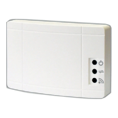
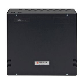
Fig. 2. LCBS Connect Gateway diagram.
6. There are four LEDs on the gateway to convey the
status of a specific function as indicated by the
adjacent icon (Fig. 2). The behavior of the LEDs will
provide troubleshooting guidance when checking
the connectivity of your system.
7. The typical behavior of a gateway will be as follows.
For complete LED behavior definitions, please see
Table 1.
a. Upon power up, the WHITE LED will first appear
with low intensity. Within a few seconds the
WHITE LED will be a higher intensity and will
remain solid.
b. After the gateway has powered up, the YELLOW
LED will initially blink once a second until a
connection to the Internet has been established
and then it will go solid.
c. Once the YELLOW LED has gone solid, the BLUE
LED will blink once a second indicating that it is
ready to be associated to a building using the
Honeywell Cloud. This can only occur if a
building has been created and is ready for a
gateway’s registration ID to be entered. After a
successful gateway registration, the BLUE LED
will go solid.
NOTE: Proceeding steps describe the registration
process.
d. The GREEN LED will initially remain off until
controllers are installed and wired to the
gateway. Once at least one controller is
connected, the GREEN LED will go solid. If a
controller that was previously connected to the
gateway has gone offline and has not been
replaced using the Honeywell Cloud Replace
function, the GREEN LED will blink once a
second.
NOTE: If the LEDs are not blinking or solid as
described, please contact your local
Honeywell LCBS Connect distributor
technical support desk for assistance, or
refer to Table 1 for troubleshooting help.
M36236A
POWER:
3-TERMINAL
CONNECTION
POWER:
BARREL
CONNECTION
ETHERNET
LON
WHITE
GREEN/YELLOW/BLUE
NET
LAN
24 VAC
COM
24 VDC
+
LCBS CONNECT GATEWAY
331-00081—03
8. Log-in to your Honeywell LCBS Connect account.
NOTE: www.lcbs.honeywell.com
9. Add the gateway under a building in the portal.
10. Make sure you enter the correct Registration ID.
Registration IDs are case-sensitive.
11. After you have added the gateway under a building
account, the gateway will automatically start send-
ing controller data to the cloud. The BLUE LED will
be SOLID ON if the gateway is able to send data to
Honeywell Cloud.
NETWORKING
• IP allocation requires a DHCP server, provided
automatically by most firewall routers.
• Firewall configuration requires port 443 or 5671
(optional).
• Gateway does not work behind an HTTP proxy and may
not work behind a transparent proxy, especially if it
requires authentication.
Refer to “Honeywell LCBS IT White Paper” for further
details.
SPECIFICATIONS
Dimensions: See Fig. 1
ELECTRICAL
Rated Voltage:
20-30 VAC, 50/60 Hz, 10 VA; 24 VDC, 1.25 A
NEMA-2 Class 2 power limited device
ENVIRONMENTAL RATINGS
Operating: 32 F – 120 F (0 C – 50 C)
Shipping and Storage: -40 F – 150 F (-40 C – 66 C)
Relative Humidity: 5% to 95% non-condensing
Enclosure Rating: IP-20, NEMA-1
OPERATION
Power Failure Backup: 24 hours at 32 to 100° F (0 to 38°
C), 22 hours at 100 to 122° F (38 to 50° C)
DEVICE CONNECTIONS
Power: 24 VDC Wall Wart or 24 VAC input
Ethernet: One (1) Ethernet interface supporting 10 Base-
T and 100 Base-TX
Network: LONworks™
APPROVAL BODIES
CUL, US listed E87741 UL916 energy management
equipment subassembly
RoHS compliance: 2011/65/EC and EN 50581:2-12
This equipment has been tested and found to comply with the limits for a Class B digital device, pursuant to part 15 of the
FCC Rules. These limits are designed to provide reasonable protection against harmful interference in a residential
installation. This equipment generates uses and can radiate radio frequency energy and, if not installed and used in
accordance with the instructions, may cause harmful interference to radio communications. However, there is no
guarantee that interference will not occur in a particular installation. If this equipment does cause harmful interference
to radio or television reception, which can be determined by turning the equipment off and on, the user is encouraged to
try to correct the interference by one or more of the following measures:
- Reorient or relocate the receiving antenna.
- Increase the separation between the equipment and receiver.
- Connect the equipment into an outlet on a circuit different from that to which the receiver is connected.
This device complies with Part 15 of the FCC rules. Operation is subject to the following two conditions: (1) this device
may not cause harmful interference, and (2) this device must accept any interference received, including interference
that may cause undesired operation.
This Class B digital apparatus complies with Canadian ICES-003.
Cet appareil numérique de la classe B est conforme à la norme NMB-003 du Canada.
This device complies with Industry Canada license-exempt RSS standard (s). Operation is subject to the following two
conditions: (1) this device may not cause interference, and (2) this device must accept any interference, including
interference that may cause undesired operation of the device.
LCBS CONNECT GATEWAY
Home and Building Technologies
In the U.S.:
Honeywell
1985 Douglas Drive North
Golden Valley, MN 55422-3992
customer.honeywell.com
® U.S. Registered Trademark
© 2017 Honeywell International Inc.
31-00081—03 M.S. Rev. 1-17
Printed in United States
Table 1. LEDs and Definitions.
Scenario Scenario Description BLUE YELLOW GREEN WHITE
Internet
1 Gateway can ping Honeywell Cloud See rows 4-7 On N/A On
2 Gateway cannot ping Honeywell Cloud Off Blink (1/sec) N/A On
Honeywell Cloud
3
Gateway is ready to be registered but is
unable to communicate with the Honeywell
Cloud; Internet is NOT working
Off Blink (1/sec) N/A On
4
Gateway is ready to be registered but is
unable to communicate with the Honeywell
Cloud; Internet is working
Blink (2/sec) On N/A On
5
Gateway is ready to be registered by
Honeywell Cloud
OR
Gateway has been registered but
recovering from offline Honeywell Cloud
Blink (1/sec) On N/A On
6Gateway has been registered and is
sending data to Honeywell Cloud On On N/A On
7
Gateway has been registered but is unable
to send data to the Honeywell Cloud;
Internet is working
Off On N/A On
8
Gateway has been registered but is unable
to send data to the Honeywell Cloud;
Internet is NOT working
Off Blink (1/sec) N/A On
9
Re-register button is held down and
gateway can send message to Honeywell
Cloud
Blink (5/sec) Previous State N/A On
10
Re-register button is held down and
gateway cannot send message to
Honeywell Cloud
Previous State Previous State N/A On
Power and Firmware
11 Firmware download in progress N/A N/A N/A On
12 Firmware installation in progress N/A N/A N/A Blink (5/sec)
13 Firmware good or installed successfully N/A N/A N/A On
14 Firmware bad and unrecoverable
automatically N/A N/A N/A Low Intensity
Lon Network
15 All previously discovered LCBS controllers
are NOT communicating N/A N/A Off On
16 All previously discovered LCBS controllers
are communicating N/A N/A On On
17 Some of the previously discovered LCBS
controllers are communicating N/A N/A Blink (2/sec) On
18 Network adapter issues. May have to
replace gateway N/A N/A Blink (1/sec) On

Other Honeywell Gateway manuals

Honeywell NetAXS-123 User guide

Honeywell

Honeywell NetAXS-123 User guide

Honeywell CIU 888 User manual

Honeywell

Honeywell CIU 888 User manual

Honeywell HON-CGW-MBB User manual

Honeywell

Honeywell HON-CGW-MBB User manual

Honeywell RFG100 User manual

Honeywell

Honeywell RFG100 User manual

Honeywell ADPRO iFT Series User manual

Honeywell

Honeywell ADPRO iFT Series User manual

Honeywell Notifier MODBUS-GW User manual

Honeywell

Honeywell Notifier MODBUS-GW User manual

Honeywell THM6000R7001 User manual

Honeywell

Honeywell THM6000R7001 User manual

Honeywell CIU 888 User manual

Honeywell

Honeywell CIU 888 User manual

Honeywell NS1 User manual

Honeywell

Honeywell NS1 User manual

Honeywell OW-CDX050 User manual

Honeywell

Honeywell OW-CDX050 User manual

Honeywell Notifier 002-467 User manual

Honeywell

Honeywell Notifier 002-467 User manual

Honeywell NFS-3030 User manual

Honeywell

Honeywell NFS-3030 User manual

Honeywell ESSER IQ8Wireless Gateway User manual

Honeywell

Honeywell ESSER IQ8Wireless Gateway User manual

Honeywell Lyric LCP300-L Product information sheet

Honeywell

Honeywell Lyric LCP300-L Product information sheet

Honeywell RedLINK User manual

Honeywell

Honeywell RedLINK User manual

Honeywell W7006A User manual

Honeywell

Honeywell W7006A User manual

Honeywell GW-1000-WE User manual

Honeywell

Honeywell GW-1000-WE User manual

Honeywell Evohome User manual

Honeywell

Honeywell Evohome User manual

Honeywell Wireless Network Master ETH/WIFI T2 User manual

Honeywell

Honeywell Wireless Network Master ETH/WIFI T2 User manual

Honeywell 290092 User manual

Honeywell

Honeywell 290092 User manual

Honeywell RedLINK THM6000R User manual

Honeywell

Honeywell RedLINK THM6000R User manual

Honeywell W8735G User manual

Honeywell

Honeywell W8735G User manual

Honeywell RedLINK THM6000R1002 User manual

Honeywell

Honeywell RedLINK THM6000R1002 User manual

Honeywell PEHA 940/8 DALI-G User manual

Honeywell

Honeywell PEHA 940/8 DALI-G User manual

Popular Gateway manuals by other brands

BEANAIR WILOW-IOT-GATEWAY-4G-MPWR quick start

BEANAIR

BEANAIR WILOW-IOT-GATEWAY-4G-MPWR quick start

RTA 460MMQT-NNA1 Product user guide

RTA

RTA 460MMQT-NNA1 Product user guide

HP hn200w owner's manual

HP

HP hn200w owner's manual

Grandstream Networks GXW42XX series user manual

Grandstream Networks

Grandstream Networks GXW42XX series user manual

Dell EMC Edge Gateway 5200 user guide

Dell

Dell EMC Edge Gateway 5200 user guide

Linksys WAG54G - Wireless-G ADSL Gateway Wireless... Quick installation guide

Linksys

Linksys WAG54G - Wireless-G ADSL Gateway Wireless... Quick installation guide

Elexa Consumer Products Guardian Bridge GBR1 user manual

Elexa Consumer Products

Elexa Consumer Products Guardian Bridge GBR1 user manual

Arris SURFboard SBG6400 user guide

Arris

Arris SURFboard SBG6400 user guide

Dell Edge Gateway 5000 Series Installation and operation manual

Dell

Dell Edge Gateway 5000 Series Installation and operation manual

ZyXEL Communications P-660HW-Tx v3 Series user guide

ZyXEL Communications

ZyXEL Communications P-660HW-Tx v3 Series user guide

Hypermedia HG-4000 3U product manual

Hypermedia

Hypermedia HG-4000 3U product manual

Winco DSE 890 WebNet installation instructions

Winco

Winco DSE 890 WebNet installation instructions

Extron electronics DA2 HD 4K Setup guide

Extron electronics

Extron electronics DA2 HD 4K Setup guide

ZyXEL Communications MAX-200M1 Series user guide

ZyXEL Communications

ZyXEL Communications MAX-200M1 Series user guide

Technicolor DCW775 installation guide

Technicolor

Technicolor DCW775 installation guide

Novell ACCESS MANAGER 3.1 SP1 - ADMINISTRATION manual

Novell

Novell ACCESS MANAGER 3.1 SP1 - ADMINISTRATION manual

Symantec Security 5600 Series, Security 5400 Series,Clientless VPN 4400... Administration guide

Symantec

Symantec Security 5600 Series, Security 5400 Series,Clientless VPN 4400... Administration guide

Ubee DVW326B Safety and installation

Ubee

Ubee DVW326B Safety and installation

manuals.online logo
manuals.online logoBrands
  • About & Mission
  • Contact us
  • Privacy Policy
  • Terms and Conditions

Copyright 2025 Manuals.Online. All Rights Reserved.