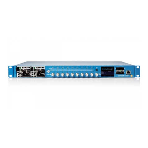
ORiNG IMG-4312-MN Series User manual

PWR 1 PWR2
10/100M
Res et
LTE
Mai n ANT.
ETH 1
WAN
ETH 2 WIFI
ETH 1
ETH 2
LTE
AUX ANT.
Rx Tx
Ser ial
WIF I ANT.
IMG-4312-MN
Ser ial
PWR 1 PWR2 PoE
10/100M
Res et
LTE
Mai n ANT.
ETH 1
WAN
ETH 2 WIFI
ETH 1
P.O.E .
ETH 2
LTE
AUX ANT.
Rx Tx
Ser ial
WIF I ANT.
IMG-4312+-MN
Ser ial
5
Quick Installation Guide
Version 1.5
Quick Installation Guide
PRINTED ON RECYCLED PAPER
Q I G 1907-200-M4312MNXX1-FX015
Installation
DIN-rail
Step 1 : Slant the device and screw the Din-rail kit onto the back of the device, right in the
middle of the back panel.
Step 2 :Slide the device onto a DIN-rail from the Din-rail kit and make sure the device clicks into
the rail firmly.
Dimension
Panel Layouts
Front Panel
1. LED for Power 1 module
2. LED for Ethernet ports
3. LED for WAN status
4. LED for Power 2 module
5. LED for Wi-Fi status
6. LTE antenna connector
7. Reset button
8. Ethernet ports (ETH1 as LAN port; ETH2 as
WAN port)
9. Wi-Fi antenna connector
10. Serial port
11. TX status of serial port
12. RX status of serial port
13. PoE indicator (IMG-4312+ Series only)
1. Din-rail screw holes
Introduction
IMG-4312-MN LPWAN (Low-Power Wide-Area Network) series Gateway
with one RS-232/422/485 serial port and two 10/100Base-T(X) ports. The
device provides an IEEE802.11b/g/n Wi-Fi interface featuring a link speed
up to 150Mbps. It can be configured to connect to the Internet by dialing up
the embedded LTE CAT-M1/ CA cellular modem. In addition, theT NB1-
device can transfer data to five host PCs simultaneously for backup
purposes. The provides P.D. function on its ETH1 portIMG-4312+-MN
which is fully compliant with IEEE802.3af PoE P.D. specification. Therefore,
it can receive power via an Ethernet cable to save installation costs and
simplify deployment. is an innovative product forIMG-4312(+)-MN Series
Cloud, Internet of Things and Industry 4.0 applications. It is a perfect choice
for remote secured data collection from the factory floor (PLCs, machines,
networking devices) and environmental sensors (temperature, humidity,
noise, pollution, vibration etc.) as well as for serving control commands
coming from Cloud Platforms for changing end-devices status.
Package Contents
The device is shipped with the following items. If any of these items is
missing or damaged, please contact your customer service representative
for assistance.
Contents
IMG-4312(+)-MN
Pictures Number
X 1
QIG X 1
LTE Antenna
Preparation
Before installation, make sure you have all of the package contents available and a PC
with Microsoft Internet Explorer 6.0 or later, for using web-based system management
tools.
Elevated Operating Ambient: If installed in a closed environment, make sure the operating
ambient temperature is compatible with the maximum ambient temperature (Tma)
specified by the manufacturer.
Reduced Air Flow: Make sure the amount of air flow required for safe operation of the
equipment is not compromised during installation.
Mechanical Loading: Make sure the mounting of the equipment is not in a hazardous
condition due to uneven mechanical loading.
Circuit Overloading: Consideration should be given to the connection of the equipment to
the supply circuit and the effect that overloading of the circuits might have on overcurrent
protection and supply wiring. Appropriate consideration of equipment nameplate ratings
should be used when addressing this concern.
Safety & Warnings
DIN-rail kit X 1
Wall-Mount Kit X 2
X 2
81.0
45.0
95.0
30.38
22.52
26.9
40.0
50.0
25.3
Rear Panel
1
Top Panel
1
2
1. Terminal block
2. Wall-mount screw holes
3. SIM card slot
4. Frame ground
Wall-mount
Step 1: Screw the two pieces of wall-mount kits to the top and bottom panels of the device. A
total of screws are required, as shown below.eight
Step 2: Use the device, with wall mount plates attached, as a guide to mark the correct locations
of the four screws.
Step 3: Insert a screw head through middle of the keyhole-shaped aperture on the plate, and
then slide the device downwards. Tighten the screw head for added stability.
Wi-Fi Antenna X 1
4-pin terminal block X 1
Dust cover X 2
134
7
3
1
2
8
9
DC12 -48V
SIM Ca rd
PWR- 1PWR- 2
V1- V1 +
V2- V2 +
3
I N D U S T R I A L
M 2 M
G at e w ay
Industrial Cellular M2M Gateway
9
3-pin terminal block X 1
29.0
13.1
23.0
43.5
8.0
14.0 1 5.5
45
23.0
22.3
10.85
Ø3.0
Ø5.9
Ø4.0
PWR1 P WR2 P oE
10/100M
Rese t
LTE
Main A NT.
ETH1
WAN
ETH2 W IFI
ETH1
P.O.E.
ETH2
LTE
AUXANT.
Rx Tx
Seri al
WIFI A NT.
IMG-4312+-MN
Seri al
Unit =mm (Tolerance ±0.5mm)
DC1 2-4 8V
SIM C ard
PWR -1PWR -2
V1- V 1+
V2- V 2+
6
10
11
12
6
4
PWR1 P WR2
10/100M
Rese t
LTE
Main A NT.
ETH1
WAN
ETH2 W IFI
ETH1
ETH2
LTE
AUX AN T.
Rx Tx
Seri al
WIFI A NT.
IMG-4312-MN
Seri al
5
4
7
3
1
2
8
9
6
10
11
12
6
PWR1 P WR2 PoE
10/ 100M
Res et
LTE
Main A NT.
ETH1
WAN
ETH2 W IFI
ETH 1
P.O.E.
ETH 2
LTE
AUX AN T.
Rx Tx
Ser ial
WIFI A NT.
IMG-4312+-MN
Seri al
IMG-4312(+)-MN Series
IMG-4312(+)-MN Series

Q I G Quick Installation Guide
PRINTED ON RECYCLED PAPER
Quick Installation Guide
Q I G
Wiring
This device supports dual redundant power supplies, Power Supply
1 (PWR1) and Power Supply 2 (PWR2). The connectors for PWR1
and PWR2 are located on the terminal block.
STEP 1: Insert the negative/positive DC wires into the V-/V+
terminals, respectively.
STEP 2: To keep the DC wires from pulling loose, use a small flat-
blade screwdriver to tighten the wire-clamp screws on the front of
the terminal block connector.
Power inputs
Grounding and wire routing help limit the effects of noise due to electromagnetic interference
(EMI). Run the ground connection from the ground screws to the grounding surface prior to
connecting devices.
Grounding
Configurations
After installing the device and connecting cables, the green power LED
should turn on. Please refer to the following tablet for LED indication.
Version 1.5
PWR- 1PWR- 2
V1- V1 +
V2- V2 +
Network Connection
The device has two 10/100Base-T(X) Ethernet ports. According to the link type, the
AP uses CAT 3, 4, 5, 5e, 6 UTP cables to connect to any other network device (PCs,
servers, switches, routers, or hubs).
Cable Type Max. Length Connector
10Base-T Cat. 3, 4, 5 100-ohm UTP 100 m (328 ft) RJ45
100Base-TX Cat. 5 100-ohm UTP UTP 100 m (328 ft) RJ45
For pin assignments for different types of cables, please refer to the following tables.
Specifications
Encl o sure IP-30
Dime n sion (W x D x H) 45( W)x80.6( D )x95(H) mm ( 1.77 x 3.17 x 3. 74 inch.)
Weight (g)
Environmental
-40 t o 85 C (-4 0 to 185 F)
o o
Storage Tem p erature
5% to 9 5% Non-con d ensing
Operating Humidi ty
Regulatory Approvals
CE EM C ( EN 55024, E N 5 5032), FCC Part 15B
EMC
EN 55 024 (IEC/E N 61000-4- 2 (ESD), IEC / EN 61000-4 -3 (RS), IEC / EN 61000- 4 -4 (EFT),
IEC / EN 61000- 4 -5 (Surge) , IEC/EN 610 0 0-4-6 (CS) , IEC/EN 610 0 0-4-8(PF MIF)
IEC / EN 61000- 4 -11 (DIP))
EMS
IEC 6 0068-2- 2 7
Shoc k
IEC 6 0068-2- 3 1
IEC 6 0068-2- 6
Vibration
Free Fall
Warranty
3 ye ars
UL6 1010-1/- 2 -201, EN60 950-1
Safe ty
-10 t o 60 C (14 t o 140 F )
o o
Operating Temperature
372 g
10/100 Base-T(X) RJ-45 Pin Assignments
Pin Number
Assignment
1 TD+
2 TD-
3 RD+
4 Not used
5 Not used
6 RD-
7 Not used
8 Not used
10/100 Base-T MDI/MDI-X Pin Assignments
Pin Number
MDI port
MDI-X port
1 TD+(transmit) RD+(receive)
2 TD-(transmit) RD-(receive)
3 RD+(receive) TD+(transmit)
4 Not used Not used
5 Not used Not used
6 RD-(receive) TD-(transmit)
7 Not used Not used
8 Not used Not used
Cable Types and Specifications.
I N D U S T R I A L
M 2 M
G at e w ay
Industrial Cellular M2M Gateway
ORing Industrial Networking Corp.
Copyright© 2019 ORing
All rights reserved.
TEL: +886-2-2218-1066
FAX: +886-2-2218-1014
Website: www.oringnet.com
E-mail: support@oringnet.com
IMG-4312(+)-MN Series
IMG-4312(+)-MN Series
LED
Color
Status
Description
PW1 Green On DC power module 1 activated
PW2 Green On DC power module 2 activated
PoE Green On PoE enabled
10/100Base-T(X) RJ45 Port
LNK/ACT Green On Port is linked and transmitting data
Serial Port
Rx Red On Port is receiving data
Tx Green On Port is transmitting data
WiFi Connection
LNK/ACT Green On Wireless network is linked
WAN Connection
LNK/ACT Green On Power is on and functioning normally
Freq u ency Band
Transmissi o n Rate
Encr y ption Security
WEP: ( 6 4-bit, 128-bit k ey supported)
WPA/WPA2: ( W EP and AES encrypt i on) 802.11i
WPA-PSK (25 6 -bit key pre-s h ared key suppor t ed)
802. 1 X Authenticat i on supported
TKIP e n cryption
Transmit Power
Receiver Sens t ivity
ORing Device Server Model
10/1 0 0Base-T(X) Ports in Auto
MDI/ M DIX 2
Physical Ports
Technology
Modu l ation
Wifi Interface
Ante n na and Connector
IMG-4312+-M N
IEE E 802.11b: C CK, DQPSK, D BPSK
IEE E 802.11g: O FDM
IEE E 802.11n: B PSK, QPSK, 1 6-QAM, 64- Q AM
Amer i ca / FCC : 2.41 2 ~2.462 GHz (11 cha n nels)
Euro p e CE / ETSI : 2.412~2 . 472 GHz (13 channel )
802. 1 1b: -90dBm±2.0 d B @ 11Mbps
802. 1 1g: -72dBm±2.0 d B @ 54Mbps
802. 1 1n(2.4G@40MH z , MCS7): -68dBm 2dBm±
801. 1 1b: 1/ 2/ 5.5/ 11 Mbps
801. 1 1g: 6/ 9/ 12/ 18/ 24/ 36 / 4 8/ 54 Mbps
802. 1 1n : UP to 15 0 M bps(40M H z)
802. 1 1b: 19dBm ±1.5 dBm
802. 1 1g: 17dBm ±1.5 dBm
802. 1 1n(2.4G@20MH z ): 16dBm 1. 5 dBm±
802. 1 1n(2.4G@40MH z ): 14dBm 1. 5 dBm±
1 x RP-SMA Female
PoE P . D. port
P.O . E.Present at E TH1
Power Device (IEE E 8 02.3af ):
IEEE 8 0 2.3af complian t i nput interface
Ove r load & short circu i t protection
Isol a tion Vo ltage: 1000 VDC mi n.
Isol a tion Resis t ance: 10 ohms min
8
IMG-4312-MN
Sim Ca r d Slot 1
Cellular Interface
Ante n na Connector
Cell u lar Standard
Band O p tion
LTE C a t-M1/Cat- N B1 :
LTE F DD:
B1/B 2 /B3/B4/B5/B8 / B12/B13/B18/B 1 9/B20/B26/B2 8
LTE C a t-M1 :
LTE T D D :B39
LTE C a t-M1/Cat-NB1
Power
Redundant Input p o wer Dua l DC inputs. 12 ~ 48VDC on 4 pi n t erminal bl ock
Power Consumpti o n(Typ.) 3.5 Watts
Ove rload current pro t ection Present
Reverse polar i ty protection Pr e sent on term inal block
Physical Characteristic
2 x SMA Female
Serial Port
Conn e ctor DB9 x1
Operation Mode RS- 2 32/422/ 4 85
Seri a l Baud Rate 110 b ps to 115.2 Kb p s
Data B i ts 7, 8
Parity odd, ev en, none, m a rk, space
Stop B i ts 1 , 1 .5, 2
RS-2 3 2 TxD, RxD, RT S, CTS, DTR, DSR, D C D, RI, GN D
Flow C o ntrol XON /XOFF, RTS/CT S, DTR / DSR
Network Protocol
Prot o col ICMP, IP, TCP, UDP, DHC P, BOOTP, SSH, DNS, SNMP V1/ V2c , HTTP S, SMTP, D D NS, PPPoE
Down l oad/Upload Rate LTE C a t-M1:300 / 37 5 Kbps
LTE C a t-NB1: 32 / 70 K b ps
-EN 55 032, CISPR 3 2, EN 61000- 3-2, EN 6100 0-3-3, FCC Part 15 cla ss A
EMI
MTBF
671 546.9934 h r s
This manual suits for next models
1
Other ORiNG Gateway manuals
ORiNG
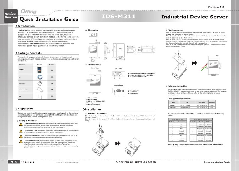
ORiNG IDS-M311 User manual

ORiNG
ORiNG IMG-W6121+-4G-M12 User manual
ORiNG
ORiNG IMG-W6121+-4G-M12 User manual

ORiNG
ORiNG IDS-M311 User manual

ORiNG
ORiNG RDS-3086 User manual
ORiNG
ORiNG IMG-4312D+-D4G User manual
ORiNG
ORiNG IMG-111-2G User manual

ORiNG
ORiNG IGMG-P83244GC+-D4G User manual

ORiNG
ORiNG IGMG-P83244GC+-D4G User manual
ORiNG
ORiNG IMG-111 User manual
