NI NHR 4808-16 User manual

Enabling Electrification
Your Partner in Test
Document Part Number 327570A-01
NHR 4808-16
DC Power Module
User Manual
September 2023

NHR 4808-16 DC Power Module User Manual
© National Instruments Corporation 1
Contents
Introduction ..............................................................................................................................3
NHR 4808-16 DC Power Module Overview...........................................................................3
Icons ......................................................................................................................................3
Warranty................................................................................................................................4
Intended Usage.....................................................................................................................4
Safety Notice – Module Does Not Have User Serviceable Parts Inside ..............................4
General Safety Notices .........................................................................................................5
Glossary................................................................................................................................. 5
What is the 4808-16 DC Power Module?...................................................................................6
Key Features of the 4808-16 DC Power Module...................................................................6
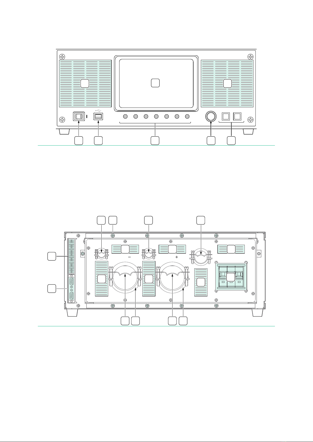
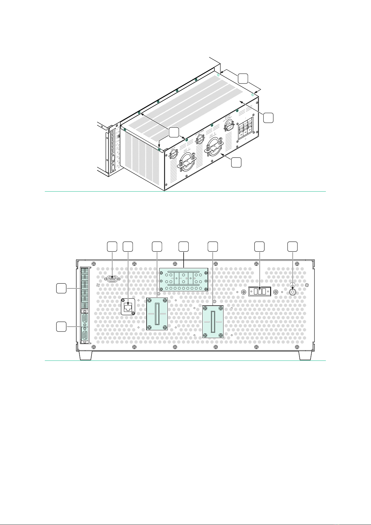
4808-16 Module Views ..........................................................................................................7
System Diagram and Theory of Operation ............................................................................10
Additional Features 4808-16 Module...................................................................................... 11
Emergency Stop Input........................................................................................................ 11
User Interlock Input............................................................................................................ 11
Programmable Trip Limits ................................................................................................. 11
Internal Monitoring.............................................................................................................11
4808-16 Module Specifications............................................................................................... 12
Electrical Output Specifications ........................................................................................12
Measurement Specifications..............................................................................................12
Trip, Mechanical, and Facility Specifications....................................................................13
Digital Interface .................................................................................................................. 14
Installing the 4808-16 Module ................................................................................................ 14
Unpacking the 4808-16 Module .........................................................................................14
Moving and Positioning the 4808 Module ......................................................................... 14
Location Mounting and Cooling.........................................................................................14
Recommended Service Feed, Breaker Size, and Facility Wiring ...................................... 15
Installing AC Facility Power................................................................................................15
Installing UUT Connections................................................................................................18
Installing LAN Connections ................................................................................................19
E-STOP and Interlock Wiring..............................................................................................19
Terminating the Parallel Interface..................................................................................... 20
Turn On and Turn Off Checklist .............................................................................................. 20
Powering Up the System....................................................................................................20
Powering Off the System.................................................................................................... 21
System Interfaces and Indicators...........................................................................................21

NHR 4808-16 DC Power Module User Manual
2 ni.com
Touch Panel Interface ........................................................................................................21
Output and System Status Indicators ...............................................................................21
Encoder Knob and Buttons ................................................................................................22
USB Port and Power Switch............................................................................................... 22
Analog IO Interface ............................................................................................................. 22
Digital IO Interface..............................................................................................................23
Paralleling IO Interface.......................................................................................................23
Air Intake.............................................................................................................................24
Touch Panel Control ...............................................................................................................25
Selecting An Operating Mode............................................................................................. 25
Wizard-Based Entry Screens ..............................................................................................26
Navigating the Wizard - On Screen Controls .....................................................................26
Example Usage – Standard Mode ...................................................................................... 26
Using the Encoder Knob and Buttons while Operating.................................................... 28
Settings Options .................................................................................................................29
External Software Control ......................................................................................................30
Maintenance............................................................................................................................ 30
Cleaning the 4808 ...............................................................................................................30
Cleaning the Module........................................................................................................... 30
Cleaning the Touch Panel Interface...................................................................................31
Calibration ..........................................................................................................................31
SCPI Programmers Reference ................................................................................................31
NI Services ...............................................................................................................................32

NHR 4808-16 DC Power Module User Manual
© National Instruments Corporation 3
Introduction
The 4808-16 DC power module is the industry leading solution for bi-directional power
testing and verification of battery modules and related systems. The 4808-16 has a built-in
contactor isolation (both facility and UUT), pre-charge, reverse polarity detection and
similar features not commonly found in commercial bi-directional power supply devices.
This manual applies to all hardware versions of the 4808-16 modules.
NHR 4808-16 DC Power Module Overview
The 4808-16 DC power module is a standalone device and consists of the following
features:
•A touch screen for manual operation
•A connection interface for an Emergency Off button
•A connection interface digital status and control
•A logic power supply for internal interlocks
•A communications port (LAN)
•Safety enclosure panels with strain reliefs for use outside of cabinets, providing:
oFacility and UUT connections (rear of unit)
oMain facility power breaker (lower rear of unit)
•Rack mountable option
•Cable accessories for wire connections, including:
oA paralleling control connection (for system expansion)
oAn input/ground connection
Icons
Refer to the following descriptions if one of these icons is marked on your product or used
in this guide.
NOTICE
Take precautions to avoid data loss, loss of signal integrity, degradation of
performance, or damage to the product.
CAUTION
Take precautions to avoid injury. Consult the product documentation for
cautionary statements when you see this icon printed on the product. Cautionary
statements are localized into French for compliance with Canadian requirements.
CAUTION: POSSIBILITY OF ELECTRIC SHOCK
Take precautions to avoid electrical shock.
PROTECTIVE CONDUCTOR TERMINAL (PE)

NHR 4808-16 DC Power Module User Manual
4 ni.com
Indicates a terminal that connects to accessible dead metal parts of the product.
Connect the PE terminal(s) to an earth ground system (protective conductor) for
safety.
Warranty
Warranty details, limitations, and other information are included within the general terms
and conditions provided with the product quote.
Intended Usage
The 4808-16 module is intended for use in temperature controlled, indoor laboratory
environments only. The product provides DC voltage control and measurement which are
primarily used in the evaluation, performance, functional, and endurance testing of
battery and supporting or similar DC products. Usage for other purposes outside of this
manual’s description which result in product failure may be considered as customer
abuse and therefore may not be covered under the warranty.
NOTICE
Operators of the equipment should be trained in safety procedures. Any damage
caused by non-intended usage is not covered under warranty.
Safety Notice – Module Does Not Have User
Serviceable Parts Inside
The 4808-16 module series contains no internally replaceable or serviceable parts.
CAUTION: POSSIBILITY OF ELECTRIC SHOCK
Internal adjustment or component replacement is only permitted by qualified NH
Research personnel. No internal adjustments or system access should be
attempted by non-NH Research personnel.
ATTENTION : POSSIBILITÉ DE CHOC ÉLECTRIQUE
Seul le personnel qualifié de NH Research peut effectuer un ajustement interne ou
le remplacement d'un composant. Aucun ajustement interne ou accès au système
ne doit être effectué par du personnel autre que NH Research.
CAUTION: POSSIBILITY OF ELECTRIC SHOCK
Remove all external voltage sources and allow a minimum of five (5) minutes for
internal capacitors to discharge before accessing terminals or servicing the
equipment.
ATTENTION : POSSIBILITÉ DE CHOC ÉLECTRIQUE
Retirer toutes les sources de tension externes et attendre au moins cinq (5)
minutes pour que les condensateurs internes se déchargent avant d'accéder aux
terminaux ou d'effectuer l'entretien de l'équipement.

NHR 4808-16 DC Power Module User Manual
© National Instruments Corporation 5
General Safety Notices
CAUTION: POSSIBILITY OF ELECTRIC SHOCK
Avoid accessing the internal components. Only a qualified electrician or trained
personnel should remove the facility service panel and output access cover. All
connections should be carried out under 0 V conditions. All connections should be
properly terminated leaving no exposed wires which could present an electrical
shock hazard. Always assume the output has potential even when OFF.
ATTENTION : POSSIBILITÉ DE CHOC ÉLECTRIQUE
Éviter d'accéder aux composants internes. Seul un électricien qualifié ou du
personnel formé peut retirer le panneau de service de l'installation et le capot
d'accès à la sortie. Toutes les connexions doivent être effectuées dans des
conditions de 0 V. Toutes les connexions doivent être correctement terminées en
ne laissant aucun fil exposé qui pourrait présenter un risque de choc électrique.
Toujours supposer que la sortie a un potentiel même si elle est sur OFF.
NOTICE
Observe all instructions and cautions in the user documentation. Using the
product in a manner not specified can damage the product and compromise the
built-in safety protection. Contact NI to report possible damage and to arrange for
repair.
NOTICE
Installation, maintenance, and servicing is only to be performed by qualified
skilled or authorized personnel. Use and operation of systems is only to be
performed by trained personnel. Systems must only be used in restricted access
locations and not accessible by ordinary persons.
Glossary
The following general terms are used throughout this document.
•Auxiliary (Module) or Auxiliary (Power Module)—An auxiliary module supplements
the power of a primary module when directed by the primary module. When
configured as an Auxiliary, it does not function independently of the primary as the
output channel is controlled by a master module.
•Battery Modules—Battery modules refer to a specific type of UUT and are a form of
battery assembly consisting of more than one cell and operating below a maximum
voltage of 80 V.
•Channel—A channel is comprised of a master output and the corresponding
auxiliary output. Each channel may be configured for DC operation as well as be
expanded by configuring and connecting an auxiliary module to produce a single
larger channel.
•Input—A generic term applied to the connection from the facility to the 4808. The
term Input does not imply the direction of power flow.

NHR 4808-16 DC Power Module User Manual
6 ni.com
•Module or Power Module—The generic name for one chassis as either standalone or
existing within the 4808 system. There are two primary module versions including a
“Primary” and an “Auxiliary”.
•Output—A generic term applied to the connection from the 4808 to the UUT. The
term Output does not imply the direction of power flow.
•Primary Module or Primary (Power Module)—A primary module contains the control
and communications hardware and the ability to instruct, command, and control
one or more auxiliary modules. Expand the current and power of a primary module
by connecting a compatible, properly configured auxiliary module.
•Unit-Under-Test (UUT)—The device being tested.
The following units apply to this document unless otherwise noted.
•Angles, degrees (°)
•Apparent power, Volt-Amperes (VA)
•Crest Factor—Calculated as the ratio of Current(AC-PEAK) to Current(AC–RMS).
•Current(AC), Amperes (ARMS)—Calculated as RMS across one cycle.
•Current(AC-PEAK), Amperes (APEAK)— Maximum instantaneous current value.
•Current(DC), Amperes (ADC)— Calculated as the average current.
•Energy, Ampere-Hours (Ah), Kilowatt-Hours (kWh)
•Frequency, Hertz (Hz)
•Power Factor—Ratio of True Power to Apparent Power.
•Resistance, Ohms (Ω)
•Time, seconds (s)
•True Power, Watts (W)
•Voltage(AC), Volts (VRMS) or VAC—Calculated as RMS across one cycle.
•Voltage(DC), Volts (VDC) or VDC—Calculated as the average voltage.
•Voltage(PEAK), Volts (VPEAK)—Maximum instantaneous voltage value observed.
•Voltage(PEAK-PEAK)—Maximum to minimum instantaneous voltage value observed.
What is the 4808-16 DC Power Module?
The 4808-16 DC power module is a regenerative, bi-directional, industry leading solution
for testing and verification of low voltage-high current battery modules, battery systems,
and related low-voltage high-current DC applications or support devices.
Key Features of the 4808-16 DC Power Module
•Built-in contactors to isolate the UUT when turned off
•Built-in automatic pre-charge and reverse polarity protection preventing high
current transitions from Off

NHR 4808-16 DC Power Module User Manual
© National Instruments Corporation 7
•Optimized for low-voltage (< 80 VDC) Power Hardware in the Loop (PHIL) applications
•Expandable voltage and current by paralleling a like module
oSame unit can be configured as the primary module or auxiliary unit
oField expandable to allow for future increased power demands
•Includes additional operating modes including uni-directional source, load, bi-
directional source/load and external control options for PHIL
NOTE
•PHIL, bi-directional, non-linear source/load (XY), and AC on DC operating
modes is limited to parallel groups of no more than 10 modules.
4808-16 Module Views
NOTICE
Avoid placing liquids near the front of the system. Accidental spills may draw into
the air intake resulting in damage to the 4808-16 power modules.
CAUTION: POSSIBILITY OF ELECTRIC SHOCK
Never insert metal objects or probes. Never allow metal fragments to be drawn
into the module openings. There are no user-serviceable parts behind the safety
cover.
ATTENTION : POSSIBILITÉ DE CHOC ÉLECTRIQUE
Ne jamais insérer d'objets métalliques ou de sondes. Ne jamais laisser de
fragment métallique entrer dans les ouvertures du module. Il n'y a pas de pièces
réparables par l'utilisateur derrière le cache de sécurité.
NOTE
NH Research recommends placing the 4808-16 module on a hard surface such as
concrete or a load bearing table with a minimum of 24 in. of unrestricted air space
to the front of each 4808-16 module in use and 30 in. air space to the rear.

NHR 4808-16 DC Power Module User Manual
8 ni.com
Figure 1: NHR 4808-16 Module – Front Exterior View
1. Touch Screen Display
2. Power Switch
3. USB Port for Touch Screen
4. Status Indicators
5. Encoder Wheel
6. Option Select Buttons
7. Air Intake
Figure 2: NHR 4808-16 Module – Rear Safety Enclosure Front Exterior View
1. Digital I/O Interface
2. UUT Connections
3. Main System Breaker
4. Air Exhaust
5. Cable Strain Reliefs
6. Paralleling Connections
7. Safety Enclosure Rear Panel Screws x10
DISCHARGECHARGEENABLED E-S TOP DSP S TA TU S LA N
O
21
ENCODER
1
7 7
2 3 4 5 6
A I N 1
G ND
A I N 2
VM O N
G ND
CM O N
DI N1
DI N2
DI N3
DI N4
G ND
5V
DO UT1
DO UT4
DO UT3
DO UT4
G ND
1 ESTO P
2 TI E 1- 2
3 DI SABL E
4 TI E 3- 4
PARALL EL I N
PARALL EL O UT
CAN/L AN 80VDC 3P+PE, 3PH, 30A, 50/60HZ
UUT UUT
80VDC 400A80VDC 400A
INPUT/GN D
380 - 480VAC
VO L TAG E SEN SE
I
O
1
6
7
5
4 4 4
444
3
55
55 2 2

NHR 4808-16 DC Power Module User Manual
© National Instruments Corporation 9
Figure 3: NHR 4808-16 Module – Rear Safety Enclosure Left-Side Front Exterior View
1. Top Panel of the Safety Enclosure
2. Top Panel Screws x11 (2 on right-side)
3. Rear Panel of the Safety Enclosure
Figure 4: NHR 4808-16 Module – Rear Safety Enclosure Interior View
1. Digital I/O Interface
2. CAN Interface
3. Sense Leads Connection
4. Facility Input Connection
5. Safety Ground Connection
6. UUT Power Connections
7. Ethernet (LAN) Connection
8. Paralleling Connections
2
2
3
1
3
A I N 1
G ND
A I N 2
VM O N
G ND
CM O N
DI N1
DI N2
DI N3
DI N4
G ND
5V
DO UT1
DO UT4
DO UT3
DO UT4
G ND
1 ESTO P
2 TI E 1- 2
3 DI SABL E
4 TI E 3- 4
PARALL EL I N
PARALL EL O UT
C AN
A B C
INPUT
3P+PE, 3PH
380 - 480VAC
30A, 50/60HZ
VO L TAG E SEN SE 80VD C
L AN
1
8
2 7 456
UUT
400A
80VDC 80V DC
400A
6
UUT
400A
80VDC 80V DC
400A

NHR 4808-16 DC Power Module User Manual
10 ni.com
Figure 5: NHR 4808-16 Module – Side View (Right Shows Tilted Touch Screen Display)
1. Rack Mount Tabs
System Diagram and Theory of Operation
The 4808-16 module uses multiple power stages to manage the power flow between the
facility and the DC testing output. In the following figure, the isolation boundary region is
shown as a vertical dashed line.
Figure 6: NHR 4808 Block Diagram
NOTICE
Do not attempt to use any internal power connections within the 4808. Only
qualified NH Research service personnel shall make any changes or connections
within the system cabinet. Modules contain NO user serviceable parts
The 4808-16 flows power in both directions between the facility input and the UUT output
through a series of power converter stages.
1 1

NHR 4808-16 DC Power Module User Manual
© National Instruments Corporation 11
•The first stage is a reversible and power factor corrected AC/DC inverter ensuring
that power is drawn with near unity power factor. The output from the first stage is a
non-isolated DC voltage.
•The second stage is an isolating high-frequency DC/DC converter which provides the
isolation between the facility input and the UUT output. The output of the second
stage is regulated low-voltage, high-current DC.
•The third stage converts the isolated internal DC to an appropriate voltage, current,
or power limited output as requested by the operator.
The system includes a set of input (facility) and output (UUT) contactors that allows the
module to be electrically isolated when the system is in an off state.
Additional Features 4808-16 Module
Emergency Stop Input
When the rear E-OFF connection is opened, the 4808-16 opens both the facility and UUT
contactors, which isolates the 4808-16 from both the facility and UUT. An error occurs to
inform the user that the emergency stop was requested, and a reset is required to return
the system to operation.
User Interlock Input
The user interlock input puts the 4808-16 module in a disabled state when the interlock
connection is open. The output relay is open and cannot close until the interlock is in a
ready condition.
Programmable Trip Limits
The 4808-16 module supports fuse-like programmable trip limits for minimum and
maximum voltages, overcurrent (per direction), and over-power (per direction). Using
these programming features, the 4808-16 module actively monitors conditions while
executing control programs. If the value and delay time exceeds limits, the module self-
commands an off state and opens its UUT relay, which isolates the module from the UUT.
Internal Monitoring
The 4808-16 module actively monitors its internal temperature and internal bus voltage,
and limits the current between the internal bus and facility power. If the 4808-16 module
detects an error, the power module self-commands an off state and opens the facility and
the UUT contactors, which isolates the module from both the facility and UUT.

NHR 4808-16 DC Power Module User Manual
12 ni.com
4808-16 Module Specifications
Electrical Output Specifications
Table 1: DC Output Ratings - Module
Model 380 VAC
Model 400 VAC
Model 480 VAC
Standard Operating
Modes
2-Quadrant with Programmable Voltage (CV), Current (CC),
Power (CP), Series-Resistance (CR)
Additional Operating
Modes
Battery Emulation, Source, Load, Bi-Directional,
Power Amplifier (PHIL), Non-Linear Source/Load (XY), AC on DC
Max Output Power
13 kW
13 kW
16.5 kW
Voltage (Full Scale)
80 V
80 V
80 V
Programming Range
0 – 102% F.S.
Programming
Accuracy
± 0.05% of Setting + 0.05% of F.S.
Programming
Resolution
0.005% F.S.
Current (Full Scale)
400 A per module
Programming Range
0 – 102% F.S.
Programming
Accuracy
± 0.1% of Setting + 0.1% of F.S.
Programming
Resolution
0.005% F.S.
Table 2: Power Amplifier Mode - Module
Model 380 VAC
Model 400 VAC
Model 480 VAC
Amplifier Type
Software Selection as Voltage or Current Amplifier
Additional Features
Programmable High/Low Limits for Voltage, Current, Power
Control Input
Analog Input ±10V PK-PK
Measurement Specifications
Table 3: DC Measurements - Module
Peak Voltage
80 VDC
Voltage Accuracy
± 0.05% of Reading + 0.05% of F.S.
Voltage Resolution
0.005% F.S.
Peak Current (per Ch.)
400 A per Module
Current Accuracy
± 0.1% of Setting + 0.1% of F.S.
Current Resolution
0.005% F.S.
Peak Power
V Range x I Range
Power Accuracy (kW or
kVA)
± 0.12% Reading + 0.12% F.S.

NHR 4808-16 DC Power Module User Manual
© National Instruments Corporation 13
Power Resolution
0.005% F.S.
Additional
Measurements
Energy (Ah, kWh), Waveform Capture
NOTE
Measurement Specifications are valid for a default aperture window or greater,
and the accuracy applies from 10% to 100% of the measurement range.
Trip, Mechanical, and Facility Specifications
Table 4: Isolation and Disable Specifications - Module
Isolation (Working
Voltage)
Input to Chassis: 480 V
Output to Chassis: 100 V
Facility to Output Internal Isolation: 480 V
Module Protection
Self-protecting for over-voltage, over-current,
over-power, and over-temperature
Physical
Emergency Stop Input and external Inter-Lock Input
Programming Trip Limits
Min/Max Voltage, Current (per direction), and Power (per
direction) with separate limits and time delay values
Watchdog Timer
Continuously monitors control communications
Table 5: Physical and Environmental Characteristics - Module
Connectors
Bus Bars
Dimension (W x H x D)
19.0 in. x 6.97 in. (4U) x 37.35 in., including the rack mount
tabs which extend 3.13 in. in front.
Module Weight
115 lb (52.16 kg)
Operating Temperature
(Humidity)
0°C to 35°C (up to 95% RH non-condensing)
Pollution Degree
2; Indoor Use Only
Altitude
2000 m maximum
Table 6: Input Power - Module
Facility Input
Universal Input – 380 V to 480 V ± 10% (L-L, 3 Phase, 3P+PE,
50/60 Hz); Maximum 277 VAC L-Gnd
Voltage Fluctuations
+/-10% maximum
Overvoltage Category
II
Efficiency
>90% typical (>92% at full power)
Power Factor
>0.95 typical (>0.99 at full power)
Current per Φ(Input)
30 A@380 VAC, 28 A@400 VAC, 25 A@480 VAC; 40 A max.
branch circuit

NHR 4808-16 DC Power Module User Manual
14 ni.com
NOTE
The 4808-16 module is equipped with a 40 A branch circuit breaker. Continuous
use must not exceed 30 A/phase.
Digital Interface
Table 7: Control - Module
Local User Interface
Built-in Touch-Panel
External System Comm
LAN (Ethernet) supporting SCPI
Drivers
NI-Compliant LabVIEW Drivers
Maximum Parallel Count
10
1
Programmable DOUT
Four (4) Output Collector Outputs
Programmable DIN
Four (4) Open Collector Inputs with internal pullup
Analog Current Monitor
[-10 V, +10 V] corresponds to ± Full Measurement Scale
Analog Voltage Monitor
[-10 V, +10 V] corresponds to ± Full Measurement Scale
Installing the 4808-16 Module
Unpacking the 4808-16 Module
Prior to shipment, the 4808-16 module was inspected and found to be free of mechanical
or electrical defects. Upon unpacking, inspect for any damage or shock watch sensors
which may indicate that the product was potentially damaged during transit. If damage is
detected, file a claim with the carrier immediately and notify NH Research Customer
Support. Be sure to keep all packing materials in case the system is to be returned to NH
Research.
NOTICE
Do not proceed with installation if the product is damaged during shipping.
Moving and Positioning the 4808 Module
The 4808-16 module weighs 115 lb (52.16 kg). NH Research recommends two people to
move and position the module.
Location Mounting and Cooling
The module is air-cooled and uses fans. Air draws from the front of the unit and exhausts
out of the rear of the unit. The recommended unrestricted air space is 24 in. (60 cm) in the
front of the unit and 30 in. (76 cm) in the rear of the unit.
1Custom configuration options available with factory consultation

NHR 4808-16 DC Power Module User Manual
© National Instruments Corporation 15
Place modules on a solid surface capable of supporting the device weight.
Recommended Service Feed, Breaker Size, and
Facility Wiring
CAUTION: POSSIBILITY OF ELECTRIC SHOCK
Avoid accessing the internal components. Only a qualified electrician or trained
personnel should remove the facility service panel and output access cover. All
connections should be carried out under 0 V conditions. All connections should be
properly terminated leaving no exposed wires which could present an electrical
shock hazard. Always assume the output has potential even when OFF.
ATTENTION : POSSIBILITÉ DE CHOC ÉLECTRIQUE
Éviter d'accéder aux composants internes. Seul un électricien qualifié ou du
personnel formé peut retirer le panneau de service de l'installation et le capot
d'accès à la sortie. Toutes les connexions doivent être effectuées dans des
conditions de 0 V. Toutes les connexions doivent être correctement terminées en
ne laissant aucun fil exposé qui pourrait présenter un risque de choc électrique.
Toujours supposer que la sortie a un potentiel même si elle est sur OFF.
NOTE
The 4808-16 module is equipped with a 40 A branch circuit breaker. Continuous
use must not exceed 30 A/phase.
This section provides general recommendations for wire gauge and service feed capacity.
You must consult a local electrician to ensure the system wire size, service feed size, and
facility breakers meet local wiring codes.
NOTE
Select the appropriate conductor size for the installation requirements, which
includes temperature and correction factors and the size of overcurrent
protection in the circuit.
Table 8: Recommended Breaker Size and Wire Gauge for the 4808-16 Module
Panel Breaker
Wire Gauge
380 L-L
40 A
8 AWG
400 L-L
40 A
8 AWG
480 L-L
40 A
8 AWG
Installing AC Facility Power
Installation requires removing safety panels which protect operators from live AC facility
connections. Before attempting installation and applying facility power, review this
section carefully as well as the Installing UUT Connections section and Turn On and Turn
Off Checklist section.

NHR 4808-16 DC Power Module User Manual
16 ni.com
NOTE
For individual modules, use only copper wire cables, 8 AWG, 600 V 90 C. Class 1
circuits only.
CAUTION: POSSIBILITY OF ELECTRIC SHOCK
Connecting the system to a three-phase AC facility power should be done by a
qualified electrician or trained personnel.
ATTENTION : POSSIBILITÉ DE CHOC ÉLECTRIQUE
La connexion du système à une alimentation CA triphasée doit être effectuée par
un électricien qualifié ou du personnel formé.
CAUTION: POSSIBILITY OF ELECTRIC SHOCK
Ensure the protective earth is properly installed before powering the system.
ATTENTION : POSSIBILITÉ DE CHOC ÉLECTRIQUE
S'assurer que la mise à la terre est correctement installée avant de mettre le
système sous tension.
CAUTION
NH Research is only able to provide general recommendations. It is the
responsibility of the end-user to consult an electrician to ensure that wiring,
breaker sizing, and associated power connections meet local ordinances.
ATTENTION
NH Research ne peut fournir que des recommandations générales. Il incombe à
l'utilisateur final de consulter un électricien afin de s'assurer que le câblage, le
dimensionnement du disjoncteur et les connexions d'alimentation associées sont
conformes aux réglementations locales.
NOTICE
Connecting the AC line input to an AC line that is unable to absorb energy quickly,
(i.e., a “soft” source) may result in an increase in voltage on the line during
regeneration. If the voltage rises to the maximum allowed, the NHR equipment
will shut down. OTHER EQUIPMENT ON THE SAME LINE MAY BE DAMAGED.
Refer to the Module Views section to locate components of the hardware.
1. Remove the screws that secure the top cover of the I/O safety enclosure at the rear
of the unit. The three-phase AC facility line connects directly to the module main
breaker located behind the front of the safety enclosure at the rear of the unit.
NOTE
Do not lose these screws as they will be needed to re-install the top cover at the
end of the installation.
2. To connect facility power, route the (3-Phase and ground) wires through the
INPUT/GND strain relief and connect the 3-Phase wires directly into the breaker.

NHR 4808-16 DC Power Module User Manual
© National Instruments Corporation 17
Figure 7: AC Input Wire Connection Diagram
3. (Optional) Remove the INPUT/GND strain reliefs. The installer may use approved
conduit entries or glands.
4. Torque wire connections to 39.8 in. ⋅lb.
NOTE
There is no phase rotation dependency for this system.
NOTE
The 4808-16 module is equipped with a 40 A branch circuit breaker. Continuous
use must not exceed 30 A/phase.
NOTICE
Do not attempt to replace or service this breaker without first consulting NH
Research Customer Service.
5. Attach the protective earthing (PE) conductor to the chassis PE terminal at the rear
of the module behind the safety cover. The PE connection has a recommended
wire gauge of 10 AWG.
6. Torque wire connections to 22 in. ⋅lb.
7. Ensure the power cable from the breaker is securely connected to the module
facility input connector. The AC input wire has a recommended line gauge size and
ground wire gauge of 10 AWG.
8. Torque the clamp screws retaining each cable until the cable is secure.
9. Reinstall the top cover of the I/O safety enclosure and torque screws to 8.7 in. ⋅lb.
The AC input installation is now complete. Proceed to install the DC and (optional) LAN
communications.

NHR 4808-16 DC Power Module User Manual
18 ni.com
CAUTION: POSSIBILITY OF ELECTRIC SHOCK
Ensure the protective earth is properly installed before powering the system.
ATTENTION : POSSIBILITÉ DE CHOC ÉLECTRIQUE
S'assurer que la mise à la terre est correctement installée avant de mettre le
système sous tension.
Installing UUT Connections
UUT connections are assumed to be semi-permanent due to the high-current and high-
power nature of the 4808-16 module. All UUT connections are behind the safety cover and
are routed out of the strain reliefs on the cover.
Consult with NH Research if other chassis modifications will be made before starting
installation.
All conductors must be copper, rated for >80 V, 90oC with a minimum 3/0 AWG – 500 MCM.
CAUTION: POSSIBILITY OF ELECTRIC SHOCK
UUT initial installation should be made by a qualified electrician or trained
personnel. Installation requires removing the safety panel that protects operators
from live AC and DC.
ATTENTION : POSSIBILITÉ DE CHOC ÉLECTRIQUE
L'installation initiale de l'unité soumise à l’essai doit être effectuée par un
électricien qualifié ou du personnel formé. L'installation nécessite le retrait du
panneau de sécurité qui protège les opérateurs contre les tensions CA et CC.
CAUTION
NH Research is only able to provide general recommendations. It is the
responsibility of the end-user to consult an electrician to ensure that wiring,
breaker sizing, and associated power connections meet local ordinances.
ATTENTION
NH Research ne peut fournir que des recommandations générales. Il incombe à
l'utilisateur final de consulter un électricien afin de s'assurer que le câblage, le
dimensionnement du disjoncteur et les connexions d'alimentation associées sont
conformes aux réglementations locales.
Refer to the Module Views section to locate components of the hardware.
1. Remove the screws that secure the top cover of the I/O safety enclosure at the
rear of the unit.
2. Prepare UUT cables using a 0.5 in. ring lug.

NHR 4808-16 DC Power Module User Manual
© National Instruments Corporation 19
3. To install the load connections, connect the UUT positive cable to the bus bar
terminal marked positive (+) and the negative cable to the bus bar terminal
marked (–).
4. Torque connections (0.5 in. – 13 brass bolts) to 442 in. ⋅lb.
5. To install the sense connections, connect the UUT sense positive cable to the
screw terminal marked positive (+) and the negative cable to the screw terminal
marked negative (–). The system requires a sense lead connection to be
measured at either the UUT output connection or as a remote measurement at
the UUT itself. The sense connection has a recommended line gauge size and
ground wire gauge of 18 AWG terminated with ring terminals.
6. Torque connections to 8 in. ⋅lb.
7. Torque the clamp screws retaining each cable until the cable is secure.
NOTICE
Do not overtighten the clamp screws. Overtightening the screws can cause
damage to the wire insulation.
8. Reinstall the top cover of the I/O safety enclosure and torque screws to 8.7 in. ⋅
lb.
Installing LAN Connections
The Ethernet control cable (if intended to be used remotely) must be routed through the
safety cover and plugged into the LAN port on the back of the module.
NOTE
Use only shielded Ethernet cables to install LAN connections.
CAUTION: POSSIBILITY OF ELECTRIC SHOCK
The facility safety cover must be in place before you power on the system.
ATTENTION : POSSIBILITÉ DE CHOC ÉLECTRIQUE
Le capot de sécurité de l'installation doit être en place avant de mettre le système
sous tension.
E-STOP and Interlock Wiring
The E-STOP and interlock wiring interfaces are located on the left rear of the module.
Figure 8: Location of E-STOP and Interlock Wiring Interfaces – Rear Module
The system accepts commands to engage only when the following conditions apply:
1 ESTOP
2 TIE 1-2
3 DISABLE
4 TIE 3-4
Table of contents
Other NI Power Supply manuals
Popular Power Supply manuals by other brands

Cooler Master
Cooler Master M2 Silent Pro user manual

Grizzly
Grizzly EASY FEEDER G0826 owner's manual

EVGA
EVGA SuperNOVA NEX 750G user manual

Siemens
Siemens SIMATIC Ident Compact operating instructions

DH Instruments
DH Instruments POWER SUPPLY KIT installation instructions

DuraComm
DuraComm LPX Series owner's guide