LifeSafety Power FlexPower Vantage FPV4 User manual

P03-057
FPV4
4 amp @ 12VDC or
3 amp @ 24VDC
FPV6
6 amp @ 12VDC or 24VDC
FPV102
10 amp @ 12VDC
FPV104
10 amp @ 24VDC
For 230VAC input add "/E" to model number - example FPV6-C8E1/E
For larger enclosure change E1 sux to E2 in model number - example FPV6-C8E2
LifeSafety Power
PH 888.577.2898
TechSupport@LifeSafetyPower.com
Power System
Installation Guide
Smart Power Supply Chargers

FlexPower Vantage Standard Power System - Installation Manual 2
Symbol Definitions
The following symbols are used throughout this manual:
h This symbol is intended to alert the installer of shock
hazards within the enclosure. Service should only be
performed by qualified service personnel.
iThis symbol is intended to alert the installer of important
information intended to help the installer avoid personal
injury or property damage.
Warnings
h Installation and service should be performed only by quali-
fied service personnel and should conform to all local codes.
h To reduce the risk of electric shock or fire, do not
expose this equipment to rain or moisture.
i This equipment shall be installed in a manner which
prevents unintentional operation by employees,
cleaning personnel, or others working in the prem-
ises, by falling objects, customers, building vibration,
or similar causes.
i This equipment is not intended for use within the patient
care areas of a Health Care Facility.
h Replace fuses only with the same type and rating as
indicated in the specifications section of this manual.
i To prevent impaired operation, ensure that all wiring is
routed and secured to prevent accidental open or short
circuit conditions.
i The system and any batteries (if used) should be tested
at least once per year to ensure proper operation.
i Batteries (if used) should be maintained at an ambient tem-
perature of between 32 and 120 degrees Fahrenheit (0-49
Celsius) or premature loss of battery power could occur.
iTest and verify output voltage before connecting the
load.
R
The equipment discussed within this manual has been
tested to the following standards:
• UL294, UL603, UL1076
• ULC S318, ULC S319
• CSA C22.2 #107.1, CSA C22.2 #205
FCC Information
Note: This equipment has been tested and found to com-
ply with the limits for a Class A digital device, pursuant to
Part 15 of the FCC Rules and ICES-003. These limits are
designed to provide reasonable protection against harm-
ful interference when the equipment is operated in a com-
mercial environment. This equipment generates, uses, and
can radiate radio frequency energy and, if not installed and
used in accordance with the instruction manual, may cause
harmful interference to radio communications. Operation of
this equipment in a residential area is likely to cause harm-
ful interference in which case the user will be required to
correct the interference at his own expense.
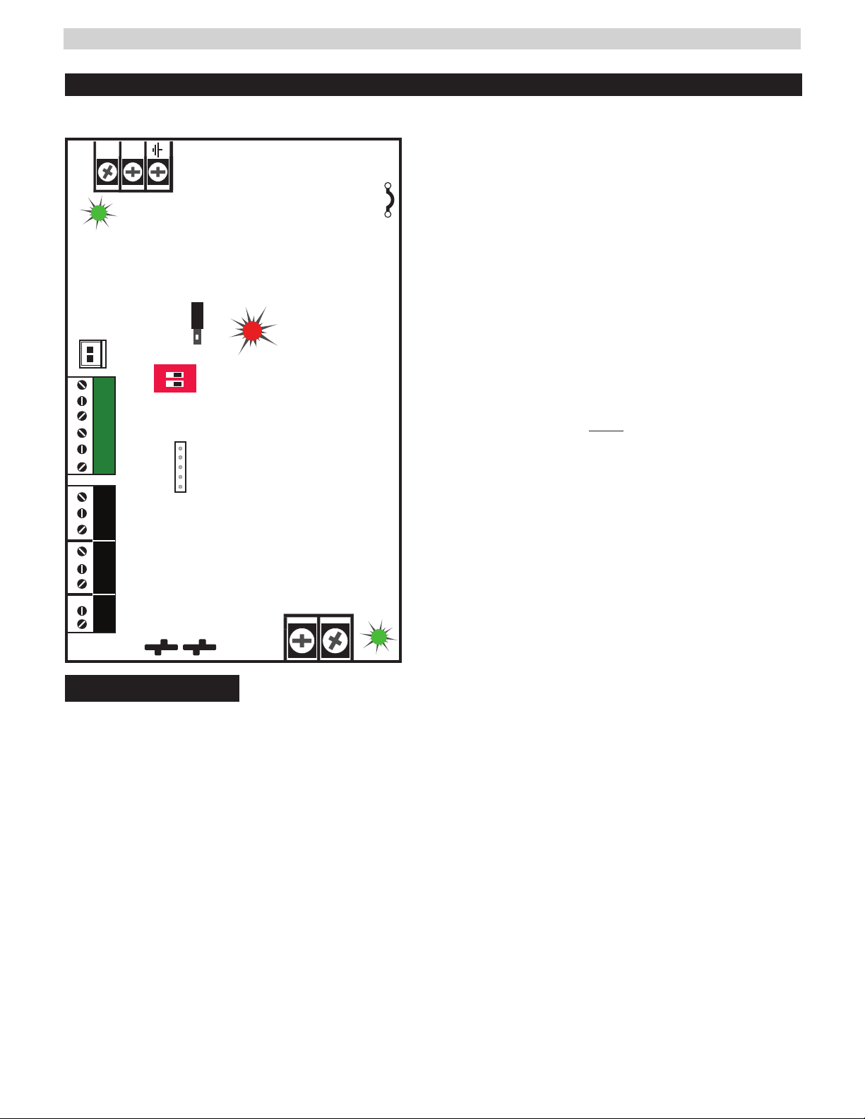
Conventions Used Within this Manual
Positional information (e.g. top, bottom, up, down, left,
right, etc.) is referenced with the board or enclosure in the
orientation shown in the illustrations in this manual.
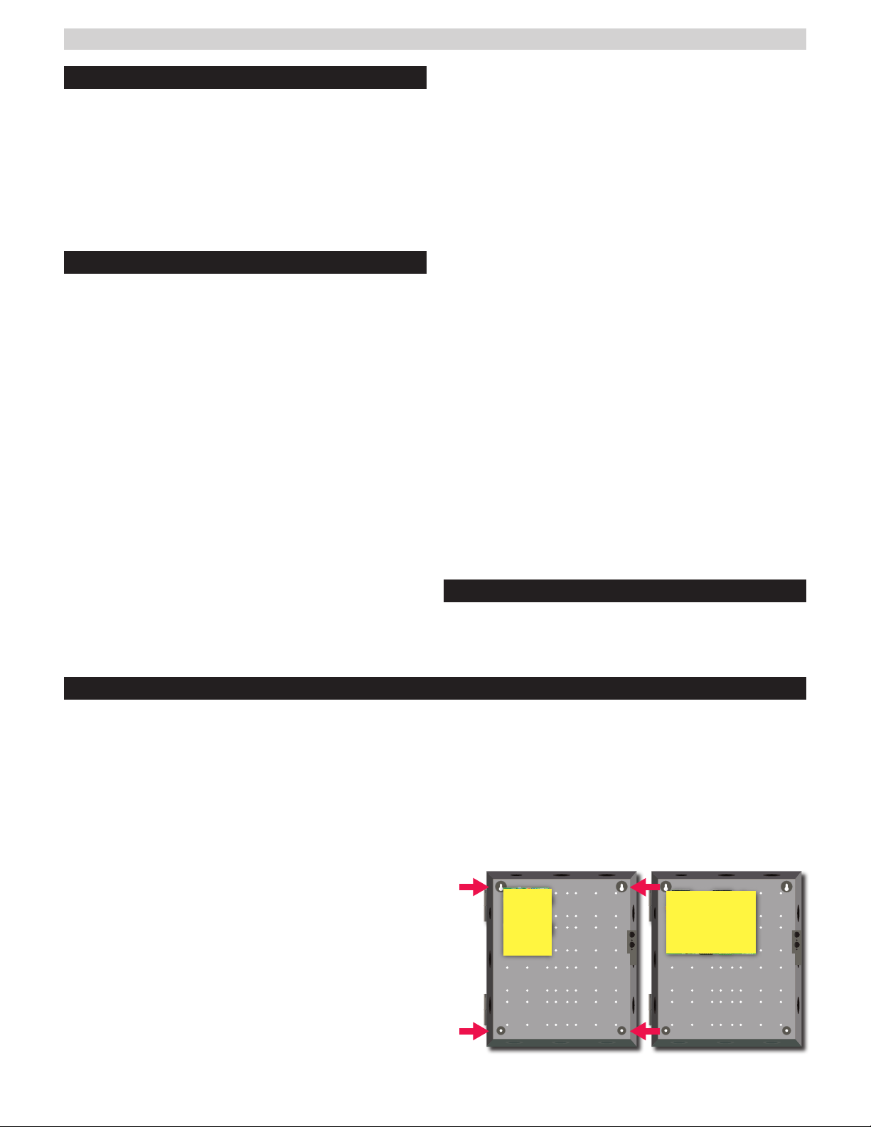
Enclosure Mounting
Mounting an Enclosure
Use the following procedure when mounting a wall-mount enclosure.
1. (Optional) Remove the enclosure’s cover.
2. Locate the top keyhole mounting holes in the back of the enclosure.
3. Mark and pre-drill the locations for the keyholes in the
mounting surface.
4. Partially install two fasteners appropriate for the sur-
face on which the enclosure is being installed. Leave the
heads of the fasteners approximately ¼" out from the
surface. Minimum fastener size should be #10 or larger.
5. Hang the enclosure on the two fasteners and mark the
locations of the remaining mounting holes.
6. Remove the enclosure and pre-drill the locations for the
remaining mounting holes.
7. Re-hang the enclosure on the top mounting fasteners,
start the remaining fasteners and tighten all fasteners.
8. Reinstall the enclosure’s cover, if removed in step 1.
iIt is the installer’s responsibility to determine the
appropriate fastening system for use with the sur-
face the enclosure is being mounted to.
iFor UL1076 applications, after installation is com-
plete, the installer must install the two supplied 1"
long screws to the edge of the enclosure's cover
for additional security.
FPV6, 102,
104
FPV4

FlexPower Vantage Standard Power System - Installation Manual 3
FPV4 Power Supply Overview
This guide gives the basic information needed to install a system containing a single Vantage Power Supply for most applications.
I See pages 4, 5 for
FPV6, FPV102 and FPV104 overview.
+
–
FAI and Charge
Current settings
FAI
N
L
Observe
battery polarity
or damage may result
Observe
battery polarity
or damage may result
i
AC Select
Voltage Select
FlexIO 12V
24V
cut jumper for
230VAC
DC ON
AC ON
ON
1 2
SYS FLTSYS FLT AC FLTAC FLT AUXAUX
FAI INPUTFAI INPUT
FPV4
I
ALWAYS DISCONNECT POWER BEFORE CHANGING
OUTPUT VOLTAGE TO PREVENT PS DAMAGE
1AC Voltage Select Jumper --
Leave INTACT for 120V input. CUT for 230V input.
I Failure to cut this jumper when using the FPV with a 230VAC
input will result in damage to the system and void the warranty.
2AC Input primary AC connection.
3AC LED (GREEN) indicates a valid AC input voltage is pres-
ent. Missing AC is indicated by this LED extinguishing.
HAlways confirm the absence of AC power with a meter
before servicing to prevent electric shock.
4Voltage Selection Jumper selects the output voltage
between 12V and 24V DC.
IRemove AC input power before changing the voltage select switch
to avoid damaging the power supply or connected equipment.
5FAI LED (RED) indicates activation of the Fire Alarm Input.
6Flex IO Connector Supplies FAI status to any accessory
boards. Receives fault signal from accessory boards.
7FAI and Charge Current Configuration Switches
Switch 1 - FAI Selection (for FAI wiring see page 6)
Off = Constant Output | On = Output switches on FAI
Switch 2 - Charge Current
Off = High Charge Current | On = Low Charge Current
8FAI Input The input from the FACP. Can be wired to accept
a NO, NC, Open Collector, or Voltage input.
See page 6 for FAI wiring information.
9System Fault Contact - Contact labeling is adjacent to the
terminals and shown in the unpowered (FAULT) condition.
bk AC Fault Contact Contact labeling is adjacent to the
terminals and shown in the unpowered (FAULT) condition.
AC fault is indicated on a missing AC Input voltage.
bl Auxiliary Voltage is a fixed Class 2 DC output.
bm Battery Terminal Connection for the optional
battery backup. Battery set voltage must match
the DC output voltage setting.
bn Main DC Output of the power supply. The output
can either be constant or switched based on the
configuration setting of switch.
• The DC ON LED will be green with voltage present.
bo DataLink Connection - This connector allows
optional programming and monitoring of the FPV
power supply via an optional NetLink network
module. See the instructions for the Netlink mod-
ule for more information.

FlexPower Vantage Standard Power System - Installation Manual 4
FPV6 Power Supply Overview -
I
Read before Power Up
This guide gives the basic information needed to install a system containing a single FPV Power supply for most applications.
1AC Input Voltage Selection
Leave INTACT for 120V input. CUT for 230V input.
IFailure to cut this jumper when using the FPV with a 230VAC
input will result in damage to the system and void the warranty.
2AC Input
The primary AC connection. Cut JP1 for 230VAC input.
3AC ON LED (green)
Indicates a valid AC input voltage is present. Missing AC is indi-
cated by this LED extinguishing.
HAlways confirm the absence of AC power with a meter
before servicing to prevent electric shock.
4FAI LED (red)
Indicates activation of the Fire Alarm Input.
5Charge Current / Main output FAI Configuration Switches
Switch 1 - FAI Selection (for FAI wiring see page 6)
Off = Constant Output | On = Output switches on FAI
Switch 2 - Charge Current
Off = High Charge Current | On = Low Charge Current
6FLEX IO Connector
Supplies FAI status to any accessory boards. Receives fault
signal from accessory boards.
7System Fault Contact
Contact labeling is adjacent to the terminals and shown in the
unpowered (FAULT) condition.
8AC Fault Contact
Contact labeling is adjacent to the terminals and shown in the
unpowered (FAULT) condition. AC fault is indicated on a missing
AC Input voltage.
9AUX Voltage
The auxiliary voltage is a fixed Class 2 Power Limited DC output.
bk FAI Input
The input from the FACP. Can be wired to accept a NO, NC, Open
Collector, or Voltage input.
See page 6 for FAI wiring information.
bl Main Output
This is the main DC output of the power supply. The output can
either be constant or switched based on the configuration setting
of switch 1 (see number 6 on this page). The DC ON LED will
light Green when 12V is present, or Blue when 24V is present.
bm Battery Terminal Connection
The connection for the optional backup battery. Battery set volt-
age must match the DC output voltage setting.
bn 12/24V Selection Jumper
This selects the output voltage between 12V and 24V DC. The
FPV Power supply must be completely powered down before
changing this setting. Voltage markings are printed on the PC
Board adjacent to the selector.
IRemove AC input power before changing the voltage select
switch to avoid damaging the power supply or connected equipment.
bo DataLink Connection - This connector allows optional
programming and monitoring of the FPV power supply via an
optional NetLink network module. See the instructions for the
Netlink module for more information.
FPV6
Voltage setting
FAI INPUTFAI INPUT
SYS FLTSYS FLT AC FLTAC FLT AUXAUX
N
L
+
–
AC INPUT
Observe battery polarity
or damage may result
Observe battery polarity
or damage may result
AC Select
cut jumper for
230VAC
i
For UL compliance, the AC fault contact
must be monitored by a listed control panel
1 2
ON
1 2
AC ON
FAI and Charge
Current settings
DC ON
FlexIO

FlexPower Vantage Standard Power System - Installation Manual 5
FPV102/104 Power Supply Overview -
I
Read before Power Up
This guide gives the basic information needed to install a system containing a single FPV Power supply for most applications.
FAI INPUTFAI INPUT
SYS FLTSYS FLT AC FLTAC FLT AUXAUX
N
L
FPV102 12V/10A
FPV104 24V/10A +
–
AC INPUT
Observe battery polarity
or damage may result
Observe battery polarity
or damage may result
AC Select
cut jumper for
230VAC
i
For UL compliance, the AC fault contact
must be monitored by a listed control panel
1 2
ON
1 2
AC ON
DC ON
FAI and Charge
Current settings
FlexIO
1AC Input Voltage Selection
Leave INTACT for 120V input. CUT for 230V input.
IFailure to cut this jumper when using the FPV with a 230VAC
input will result in damage to the system and void the warranty.
2AC Input
The primary AC connection. Cut JP1 for 230VAC input.
3AC ON LED (green)
Indicates a valid AC input voltage is present. Missing AC is indi-
cated by this LED extinguishing.
HAlways confirm the absence of AC power with a meter
before servicing to prevent electric shock.
4FAI LED (red)
Indicates activation of the Fire Alarm Input.
5Charge Current / Main output FAI Configuration Switches
Switch 1 - FAI Selection (for FAI wiring see page 6)
Off = Constant Output | On = Output switches on FAI
Switch 2 - Charge Current
Off = High Charge Current | On = Low Charge Current
6FLEX IO Connector
Supplies FAI status to any accessory boards. Receives fault
signal from accessory boards.
7System Fault Contact
Contact labeling is adjacent to the terminals and shown in the
unpowered (FAULT) condition.
8AC Fault Contact
Contact labeling is adjacent to the terminals and shown in the
unpowered (FAULT) condition. AC fault is indicated on a missing
AC Input voltage.
9AUX Voltage
The auxiliary voltage is a fixed Class 2 Power Limited DC output.
bk FAI Input
The input from the FACP. Can be wired to accept a NO, NC, Open
Collector, or Voltage input.
See page 6 for FAI wiring information.
bl Main Output
This is the main DC output of the power supply. The output can
either be constant or switched based on the configuration setting
of switch 1 (see number 6 on this page). The DC ON LED will
light Green on the FPV102, or Blue on the FPV104. If this LED
lights the wrong color, contact tech support.
bm Battery Terminal Connection
The connection for the optional backup battery. Battery set volt-
age must match the DC output voltage setting.
Power Supply Fixed Voltage:
FPV102: 12V / 10 Amps
FPV104: 24V / 10 Amps
bn DataLink Connection - This connector allows optional
programming and monitoring of the FPV power supply via an
optional NetLink network module. See the instructions for the
Netlink module for more information.

FlexPower Vantage Standard Power System - Installation Manual 6
FAI Input Usage
Activation with a Normally Open Relay Contact
FAI Activates when the
NO contact CLOSES.
FAI Deactivates when the
NO contact OPENS.
Activation with a Normally Closed Relay Contact
FAI Activates when the
NC contact OPENS.
FAI Deactivates when the
NC contact CLOSES.
Note: FAI with a NC contact
cannot be tested by removing
the terminal strip, as this will
remove the jumper wires from
V+ and V- as well. To test,
remove one wire going to the
NC Contact.
Activation with a Voltage Input
FAI Activates when voltage is AP-
PLIED in the correct polarity. FAI
Deactivates when voltage is RE-
MOVED. Do not connect a polarity
reversal circuit (NAC) to the FPV.
Latching the FAI Input
Latching of the FAI Input
is achieved by placing a
NC contact across the
two ‘L’ terminals. The FAI
may be activated by any
of the methods listed.
FAI Deactivates when the
input is deactivated AND
the NC Latching contact is
momentarily OPENED.
Example – NO Contact
activation with latching
FAI Activates when the NO contact CLOSES. FAI Deactivates
when the NO contact OPENS AND the NC contact momentarily
OPENS.
FAI Activation with a Normally Open Relay Contact
and FPV AC Fault Lock Over Ride
FAI Activates either, when the Fire Alarm NO contact CLOSES,
or when the AC Fault NC contact CLOSES
FAI Deactivates either, when the Fire Alarm NO contact OPENS,
or when the FPV AC Fault NC contact OPENS
SYS ACSYS AC
FAULTSFAULTS
FAI
INPUT
CC NCNC NONO CC NCNC NONO
FAI INPUTFAI INPUT
LL LL V–V– I–I– I+I+ V+V+
FAI INPUTFAI INPUT
LL LL V–V– I–I– I+I+ V+V+
NO
Contact
NC
Contact
FAI INPUTFAI INPUT
LL LL V–V– I–I– I+I+ V+V+
9-30 VDC
–
+
FAI INPUTFAI INPUT
LL LL V–V– I–I– I+I+ V+V+
NO
Contact
NC
Contact
FAI INPUTFAI INPUT
LL LL V–V– I–I– I+I+ V+V+
This section provides more detailed information on the connection and usage of the FAI Input located on the main power
supply board.

FlexPower Vantage Standard Power System - Installation Manual 7
Tamper Switch Wiring
Typical Installation and Wire Routing
Vantage power supply systems with an enclosure may in-
clude a normally closed tamper switch for monitoring by
the host panel. The tamper switch can either be brought
into a dedicated input in the panel (see the panel's instruc-
tions), or the tamper switch may be series connected into
the System Fault relay in the FPV supply (see Figure 1).
Any UL1076 installation must use the tamper switch to
indicate the opening or removal of the front door of the
enclosure.
Figure 2 shows a typical installation.
Actual configuration and wire routing will vary based on
the components installed in your system.
The following guidelines should be followed for installation:
• Class 2 Power limited wiring must be separated from
non-power limited wiring by a minimum of 1/4 inch
and must use separate knockouts.
• Any wiring passing through knockouts in the bottom or
top surfaces of the enclosure must be enclosed in rigid
or flexible metal conduit.
• Canadian Installations - For permanently connected
equipment, a readily accessible disconnect device shall
be incorporated external to the equipment. Output cir-
cuits not connected to removable terminal strips shall
also utilize a readily accessible disconnect device.
SYS FAULT
AC FAULT AUX
C NC NO
Tamper
Switch
Fault Connections
to Panel
FPV Power Supply
Figure 1 - Tamper switch fault relay wiring
FPV6, 102, 104
N
L
BATTERY
AC INPUT
FPV4
BATTERY
NL
AC INPUT
Figure 2 - Wiring

FlexPower Vantage Standard Power System - Installation Manual 8
FPV4 / FPV6 Electrical / Mechanical Specifications
FPV4 FPV6
AC Input Voltage 120VAC or 230VA at 50-60Hz 120VAC or 230VAC at 50-60Hz
Current 1.8A maximum 3.7A maximum
Standby Current 80mA 150mA
DC Output at 12V Setting
(Auxiliary power-limited output
rated at 1.5A. Total current must
not exceed max current)
Voltage 11.3 - 12.0V 11.2 - 12.0V
Max Current 4A 6A
Ripple & Noise 120mV 120mV
Regulation ±2% ±2%
Efficiency 82% (120VAC
60Hz In, Full Load, No Batt)
88% (120VAC
60Hz In, Full Load, No Batt)
Auxiliary Output (12V) Current 1.5 A max 1.5 A max
DC Output at 24V Setting
(Auxiliary power-limited output
rated at 1.5A. Total current must
not exceed max current)
Voltage 23.5 - 24.0 23.2 - 24.0
Max Current 3A 6A
Ripple & Noise 240mV 240mV
Regulation ±2% ±2%
Efficiency 83% (120VAC 60Hz Input,
Full Load No Batt)
85% (120VAC 60Hz Input,
Full Load No Batt)
Auxiliary Output (24V) Current 1.5 A max 1.5 A max
Battery Size & Type 4-40AH Lead Acid
or Gel Cell
4-80AH Lead Acid
or Gel Cell
Charge Current 1A (±10%) maximum
adjustable via DIP switch. 1.0A
high setting, 0.5A low setting.
1.6A (±10%) maximum
adjustable via DIP switch. 1.6A
high setting, 0.8A low setting.
Low battery disconnect to
prevent deep discharge
70% of nominal
battery voltage
70% of nominal
battery voltage
Fuse Rating Battery ATM 15A ATM 15A
BTU Output BTU/Hr 34-41 44-62
Fault Setpoints Low AC 95V (±6%) 95V (±6%)
Output Voltage ±10% of nominal ±10% of Nominal
Fault Relay Contacts AC FLT 1A at 24VDC 1A at 24VDC
SYS FLT 1A at 24VDC 1A at 24VDC
Operating Temperature 0 – 49C° 0 – 49C°
Board Size / Weight 6.0L x 4.0W x 2.50"H | 1.0 lbs 8.25L x 5.50W x 2.50"H |1.0 lbs
Enclosure Size / Weight 14H x 12W x 4.5"D | 14 lbs 14H x 12W x 4.5"D | 14 lbs

FlexPower Vantage Standard Power System - Installation Manual 9
FPV102 / FPV104 Electrical / Mechanical Specifications
FPV102 FPV104
AC Input Voltage 120VAC or 230VAC at 50-60Hz 120VAC or 230VAC at 50-60Hz
Current 3A 5.7A
Standby Current 110mA 160mA
DC Output
(Auxiliary power-limited
output rated at 1.5A.
Total current must not
exceed max current)
Voltage 11.3 - 12.0V 23.4 - 25.0V
Max Current 10A 10A
Ripple & Noise 120mV 240mV
Regulation ±2% ±2%
Efficiency 89% (120VAC
60Hz In, Full Load, No Batt)
91% (120VAC
60Hz In, Full Load, No Batt)
Auxiliary Output Current 1.5 A max 1.5 A max
Battery Size & Type 4-80AH Lead Acid
or Gel Cell
4-80AH Lead Acid
or Gel Cell
Charge Current 1.6A (±10%) maximum.
Charger current is 1.6A max for high
setting, 0.8A max for low setting.
1.6A (±10%) maximum.
Charger current is 1.6A max for high
setting, 0.8A max for low setting.
Low battery disconnect to
prevent deep discharge
70% of nominal
battery voltage
70% of nominal
battery voltage
Fuse Rating Battery ATM 15A ATM 15A
BTU Output BTU/Hr 55 92
Fault Setpoints Low AC 95V (±6%) 95V (±6%)
Output Voltage ±10% of Nominal ±10% of Nominal
Fault Relay Contacts AC FLT 1A at 24VDC 1A at 24VDC
SYS FLT 1A at 24VDC 1A at 24VDC
Operating Temperature 0 – 49C° 0 – 49C°
Board Size / Weight 8.25L x 5.50W x 2.50H |1.0 lbs 8.25L x 5.50W x 2.50"H |1.0 lbs
Enclosure Size / Weight 14H x 12W x 4.5"D | 14 lbs 14H x 12W x 4.5"D | 14 lbs

FlexPower Vantage Standard Power System - Installation Manual 10
1. The power supply must be installed within the protected area.
2. The LifeSafety Model EB-80 must be used to house the required battery(ies) when capaaacites of 40 to 80Ah are required. The
EB-80 shall be mounted within 6ft of the power supply and the wiring enclosed in conduit.
3. Connections to the SYS FLT, AC FLT, and FAI inputs shall be completed within the same room, not exceeding a length of 3m.
4. Do not connect equipment to an AC power source that is controlled by a switch.
5. The power supplies shall be mounted in a Listed LifeSafety Power enclosure.
6. Trouble contacts shall be monitored by a listed alarm system.
The following sections cover specific requirements based on application:
UL1076, Proprietary Burglar Alarm Applications:
1. The LifeSafety tamper switch must be employed to monitor the power supply.
2. To achieve 4 hours of standby at full load current, 80Ah min. battery capacity is required for the FPV102 or FPV104. To achieve 4
hours of standby at full load current, 40Ah min. battery capacity is required for the FPV4 and FPV6.
S319, Access Control Applications:
1. The LifeSafety tamper switch must be employed to monitor the power supply.
For UL Compliance:
Any locking device shall be configured for fail safe operation upon occurrence of an alarm as shown in Activation with a Normally
Closed Relay Contact in page 6, FAI Input Usage.
General Applications
© 2019 LifeSafety Power Inc.P03-057Rev A0507/19
IMPORTANT
All information, including illustrations, is believed to be reliable. Users, however, should independently evaluate the suitability of each
product for their particular application. LifeSafety Power makes no warranties as to the accuracy or completeness of the information,
and disclaims any liability regarding its use. LifeSafety Power’s only obligations are those in the LifeSafety Power Standard Terms
and Conditions of Sale for this product, and in no case will LifeSafety Power or its distributors be liable for any incidental, indirect, or
consequential damages arising from the sale, resale, use, or misuse of the product. Specifications are subject to change without notice.
In addition, LifeSafety Power reserves the right to make changes—without notification to Buyer—to processing or materials that do not
aect compliance with any applicable specification.
LifeSafety Power
899 E. Park Avenue
Libertyville, IL 60048 USA
www.lifesafetypower.com
Phone (888) 577-2898
info1@lifesafetypower.com
This manual suits for next models
5
Table of contents
Other LifeSafety Power Power Supply manuals

LifeSafety Power
LifeSafety Power FlexPower Generation 2 User manual

LifeSafety Power
LifeSafety Power Helix RH150 Series User manual

LifeSafety Power
LifeSafety Power B100 User manual

LifeSafety Power
LifeSafety Power FLEXPOWER RC75 Series User manual

LifeSafety Power
LifeSafety Power Helix User manual

LifeSafety Power
LifeSafety Power FlexPower RA150 Series User manual

LifeSafety Power
LifeSafety Power FlexPower User manual

LifeSafety Power
LifeSafety Power FlexPower Vantage R8 series User manual

LifeSafety Power
LifeSafety Power FlexPower User manual

LifeSafety Power
LifeSafety Power FLEXPOWER iSCAN RS Series User manual