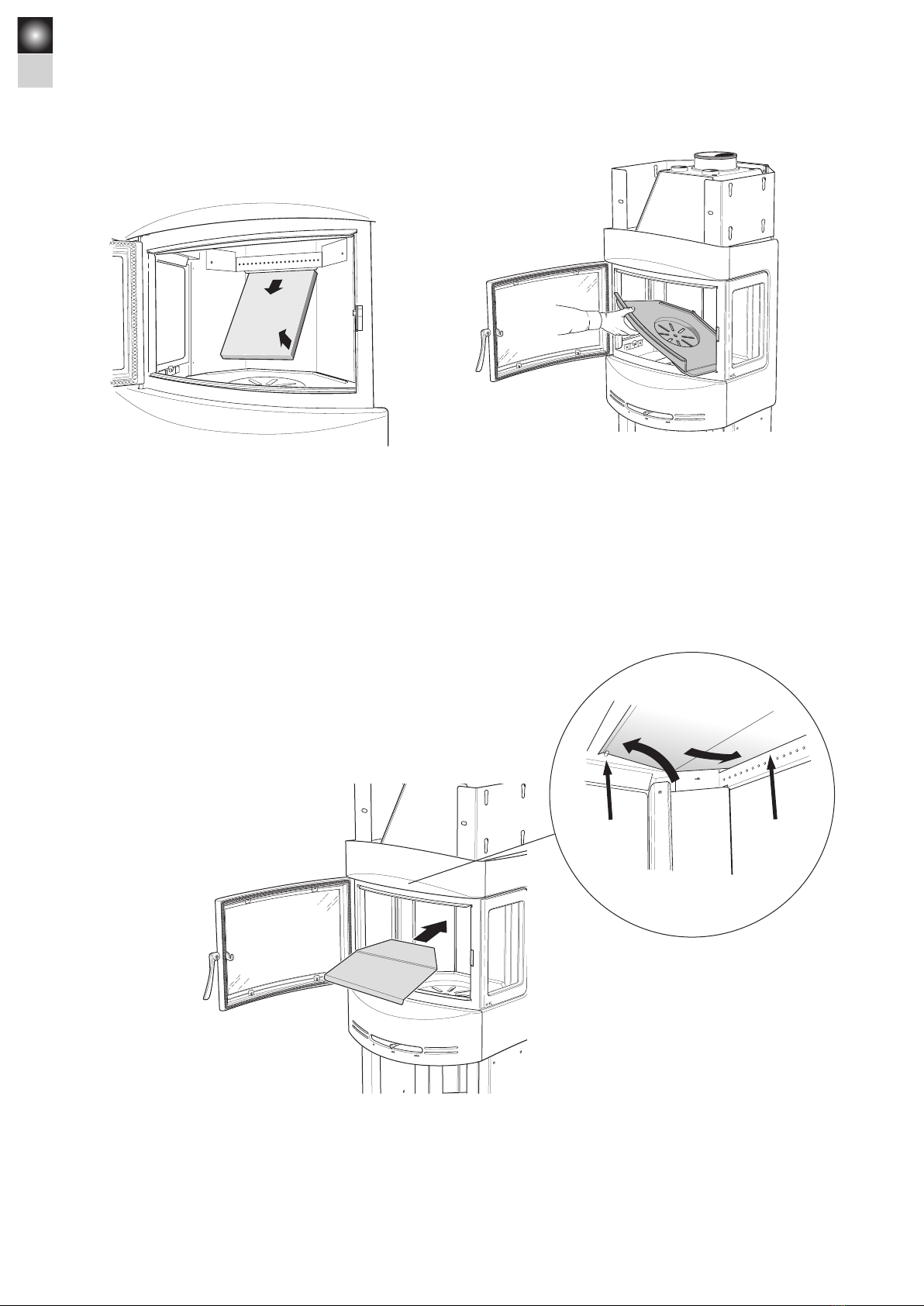
manuals.online logo
Brands
  1. Home
  2. •
  3. Brands
  4. •
  5. Nibe
  6. •
  7. Stove
  8. •
  9. Nibe Contura C480 User manual

Nibe Contura C480 User manual

Other Nibe Stove manuals

Nibe Contura C586 User manual

Nibe

Nibe Contura C586 User manual

Nibe Contura C750 User manual

Nibe

Nibe Contura C750 User manual

Nibe Contura C620 User manual

Nibe

Nibe Contura C620 User manual

Nibe Contura C520T User manual

Nibe

Nibe Contura C520T User manual

Nibe Contura Ci51 User manual

Nibe

Nibe Contura Ci51 User manual

Nibe Contura C596 User manual

Nibe

Nibe Contura C596 User manual

Nibe Contura C690T User manual

Nibe

Nibe Contura C690T User manual

Nibe Contura C596 User manual

Nibe

Nibe Contura C596 User manual

Nibe Contura C556T User manual

Nibe

Nibe Contura C556T User manual

Nibe Contura C510 User manual

Nibe

Nibe Contura C510 User manual

Nibe Contura C30 User manual

Nibe

Nibe Contura C30 User manual

Nibe Contura 51 User manual

Nibe

Nibe Contura 51 User manual

Nibe Contura Ci7G User manual

Nibe

Nibe Contura Ci7G User manual

Nibe Contura C596 User manual

Nibe

Nibe Contura C596 User manual

Nibe Contura C690AG User manual

Nibe

Nibe Contura C690AG User manual

Nibe Contura C810L User manual

Nibe

Nibe Contura C810L User manual

Nibe Contura C 50 User manual

Nibe

Nibe Contura C 50 User manual

Nibe Contura Ci10 User manual

Nibe

Nibe Contura Ci10 User manual

Nibe Contura 655 User manual

Nibe

Nibe Contura 655 User manual

Nibe Contura C610 Style User manual

Nibe

Nibe Contura C610 Style User manual

Popular Stove manuals by other brands

Quadra-Fire Discovery I Wood Appliance installation manual

Quadra-Fire

Quadra-Fire Discovery I Wood Appliance installation manual

Wildfire F-131 2 Series User instructions

Wildfire

Wildfire F-131 2 Series User instructions

Dansons Group Pit Boss PB820FB1 manual

Dansons Group

Dansons Group Pit Boss PB820FB1 manual

Sylvania SO111R-MBK instruction manual

Sylvania

Sylvania SO111R-MBK instruction manual

Breckwell SP6000 Installation & operator's manual

Breckwell

Breckwell SP6000 Installation & operator's manual

Breckwell P24FSA owner's manual

Breckwell

Breckwell P24FSA owner's manual

Bartscher 1509851 instruction manual

Bartscher

Bartscher 1509851 instruction manual

Continental Fireplaces CDVS280-1NSB Installation and operation manual

Continental Fireplaces

Continental Fireplaces CDVS280-1NSB Installation and operation manual

Arada Cassette Stove installation guide

Arada

Arada Cassette Stove installation guide

Astonica 40100008 instruction manual

Astonica

Astonica 40100008 instruction manual

Cattara FAMILY manual

Cattara

Cattara FAMILY manual

Stanley Argon F500 OVAL Installation and operating instructions

Stanley

Stanley Argon F500 OVAL Installation and operating instructions

Nordpeis Vega user manual

Nordpeis

Nordpeis Vega user manual

Exquisit EKC601-5 Instructions for use and installation

Exquisit

Exquisit EKC601-5 Instructions for use and installation

Stanley Oisin Oil MK II Installation and operation instruction

Stanley

Stanley Oisin Oil MK II Installation and operation instruction

HASE delhi operating instructions

HASE

HASE delhi operating instructions

Vermont Castings Intrepid 2 User instructions

Vermont Castings

Vermont Castings Intrepid 2 User instructions

Italiana Camini CLASSICA Installation, use and maintenance

Italiana Camini

Italiana Camini CLASSICA Installation, use and maintenance

manuals.online logo
manuals.online logoBrands
  • About & Mission
  • Contact us
  • Privacy Policy
  • Terms and Conditions

Copyright 2025 Manuals.Online. All Rights Reserved.

C480
Installationsanvisning 2
Installationsanleitung 18
Installasjonsanvisning 34
Installation instruction 50
SE
DE
NO
GB
Installation
instruction
contura.eu
50
GB
PRODUCT
Product type Stove lit with solid biofuels
Type designation Contura 480
Manufacturing number See rating plate on the stove
Intended area of use Heating of rooms in residential buildings
Fuel Wood
MANUFACTURER
Name NIBE AB / Contura
Address Box 134, Skulptörvägen 10
SE-285 23 Markaryd, Sweden
CHECKS
According to AVCP System 3
European standard EN 13240:2001 / A2:2004
Test institute Rein-Ruhr Feuerstätten Prüfstelle, NB 1625,
has checked declared performance and issued test report no. RRF-40 05 932
Declaration of performance according
to Regulation (EU) 305/2011
No. C480-CPR-130605-SE-1
DECLARED PERFORMANCE
Essential characteristics Performance Harmonised technical
specification
Reaction to fire A1 WT
Minimum distance to combustible material Rear: 100 mm
Side: 494 mm
Other safety distances according to
the installation instructions
Risk of falling embers Pass
Emissions from combustion CO 0.12%
Surface temperatures Pass
Cleaning options Pass
Mechanical durability Pass
Emissions of hazardous substances Pass
Nominal output 7 kW
Efficiency 80%
Flue gas temperature in connector at nominal
output
255°C
EN 13240:2001 / A2:2004
The undersigned is responsible for the manufacture and conformity with the declared performance.
Niklas Gunnarsson, Business area manager NIBE STOVES
Markaryd, 1st July 2013
51
GB
Contents
Technical specifications 52
Installation distances to walls and ceilings 53
Air supply 54
Unpacking the stove 55
Installing the smoke baffle 56
Connection to the flue 57
Assembling the soapstone surround 58
Installing the fan (optional extra) 62
Fitting an extra glass side panel (optional extra) 64
How to use your wood-burning stove 65
A warm welcome to Contura
A warm welcome to the Contura family. We hope you
will get a great deal of pleasure from your new stove.
As a new owner of a Contura stove, you have secured
a product with timeless design and long service life.
Contura also has a combustion process that is both
environmentally friendly and efficient, for the best heat
production.
Read through these installation instructions carefully
before installation. Read how to best light your stove
in the lighting instructions.
NOTE!
Report the installation of a stove to your
local authority.
The owner of the house is personally responsible
for ensuring compliance with the mandatory safety
requirements and must have the installation approved by
a qualified inspector. Your local chimney sweep must also
be informed about the installation as this will affect the
routines for regular chimney-sweeping services.
WARNING!
The stove becomes very hot
During operation, certain surfaces of the stove become very
hot and can cause burn injury if touched. Also, take heed
of the strong heat radiated through the door glass. Placing
flammable material closer than the safe distance indicated
may cause a fire. Smoulder combustion can cause quick gas
ignition with the risk of damage to property and personal
injury.
52
GB
Rökhylla
Rostertallrik
Gjutgodsbotten
Täckbitar
Brasbegränsare
Asklåda
Eldstadsbeklädnad
Plåtprofiler
Technical specifications
Output ..................................3–9 kW
Efficiency, up to ..........................80%
Weight ..................................290 kg
Stove width ..............................552 mm
Depth ...................................526 mm
Height ...................................1250 mm
Connecting sleeve (internal dia.). ..........Ø150 mm
Type approved in accordance with:
European standard EN-13240 class 1
Swedish environmental and quality certification,
“P marked” cert. no. 22 03 07
Swedish type approval, cert. no. 0887/99
Norwegian standard NS 3059, certificate no. 043-088
German standard DIN 18.891, RO-91 99 84
Danish standard 887-1,ID nr 598
General information
This folder contains instructions on how to assemble and install
stoves in the Contura 480. The stove also comes with comprehen-
sive Lighting and Maintenance Instructions. Please take time to
read all this information carefully and keep it in a safe place for
future reference.
Contura 480 stoves have been type-approved in Sweden for con-
nection to a chimney which can withstand flue gas temperatures
of 350 °C. The connecting sleeve has an external diameter of 150
mm.
To ensure proper combustion, sufficient air must be supplied to
the stove from outdoors.
A convector fan is available as an optional extra for your stove. If
you require further advice and instructions concerning the instal-
lation of a wood-burning stove, we recommend that you contact
your local chimney sweep or the relevant authority in your area.
Building permission
It may be necessary for you to apply for building permission from
your local planning authority before installing a stove or erecting
a chimney. Before starting installation work, make sure that you
check which regulations apply.
Structural support
Check to make sure that the floor is strong enough to support the
weight of the stove and chimney. If you intend to locate the stove
on standard wooden floor joists, contact a professional builder
to make sure that the construction will withstand the load. If the
total weight of the stove and chimney together does not exceed
400 kilos, it is not usually necessary to reinforce the joists
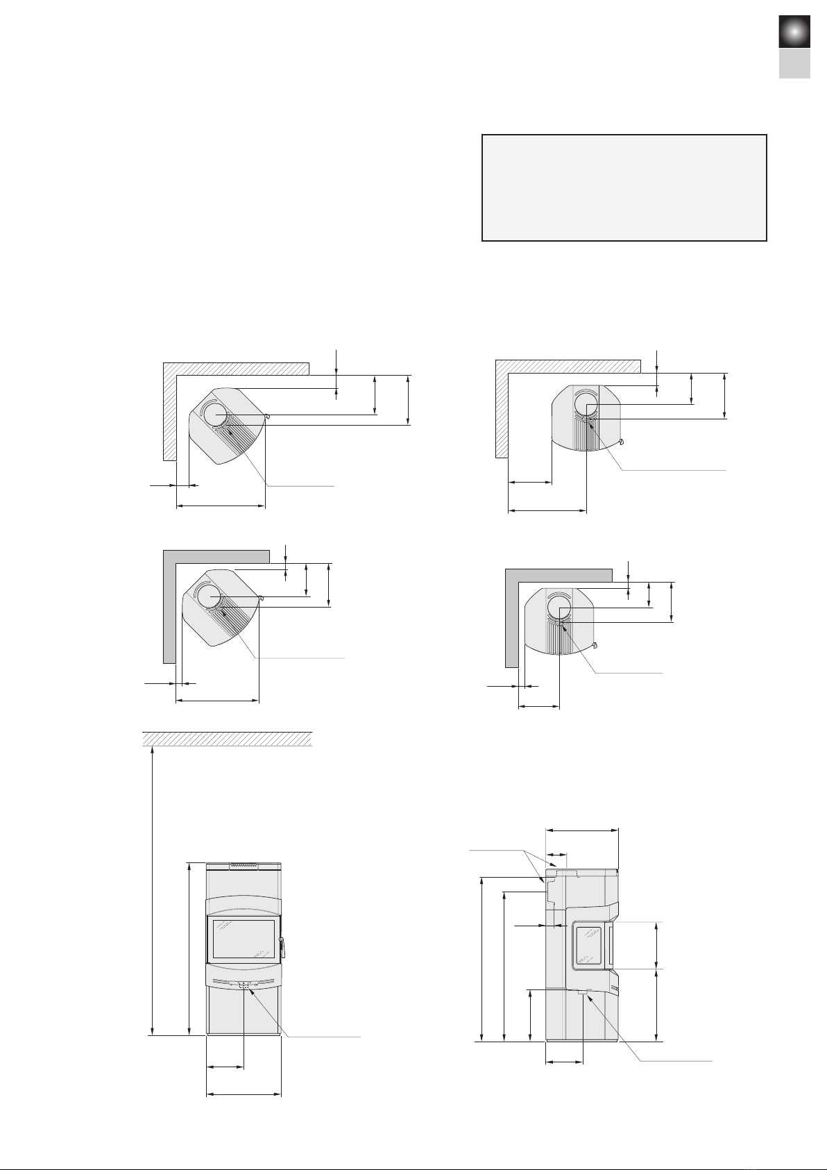
Floor plate
To protect the floor from sparks and falling embers the stove
must stand on a non-combustible surface which extends at least
300 mm in front of the stove and 100 mm along each side. As
other statutory requirements apply in some countries, we recom-
mend that you consult the relevant authority or an authorised
chimney-sweep in your area.
Chimney
The draught in the chimney must generate a negative pressure
of at least 12 Pa. The draught is affected both by the length and
cross-sectional area of the chimney, and by how well sealed the
construction is. The shortest recommended chimney length is 3.5
metres. The cross-sectional area of the chimney must be approx-
imately 150–200 cm² (140–160 mm in diameter).
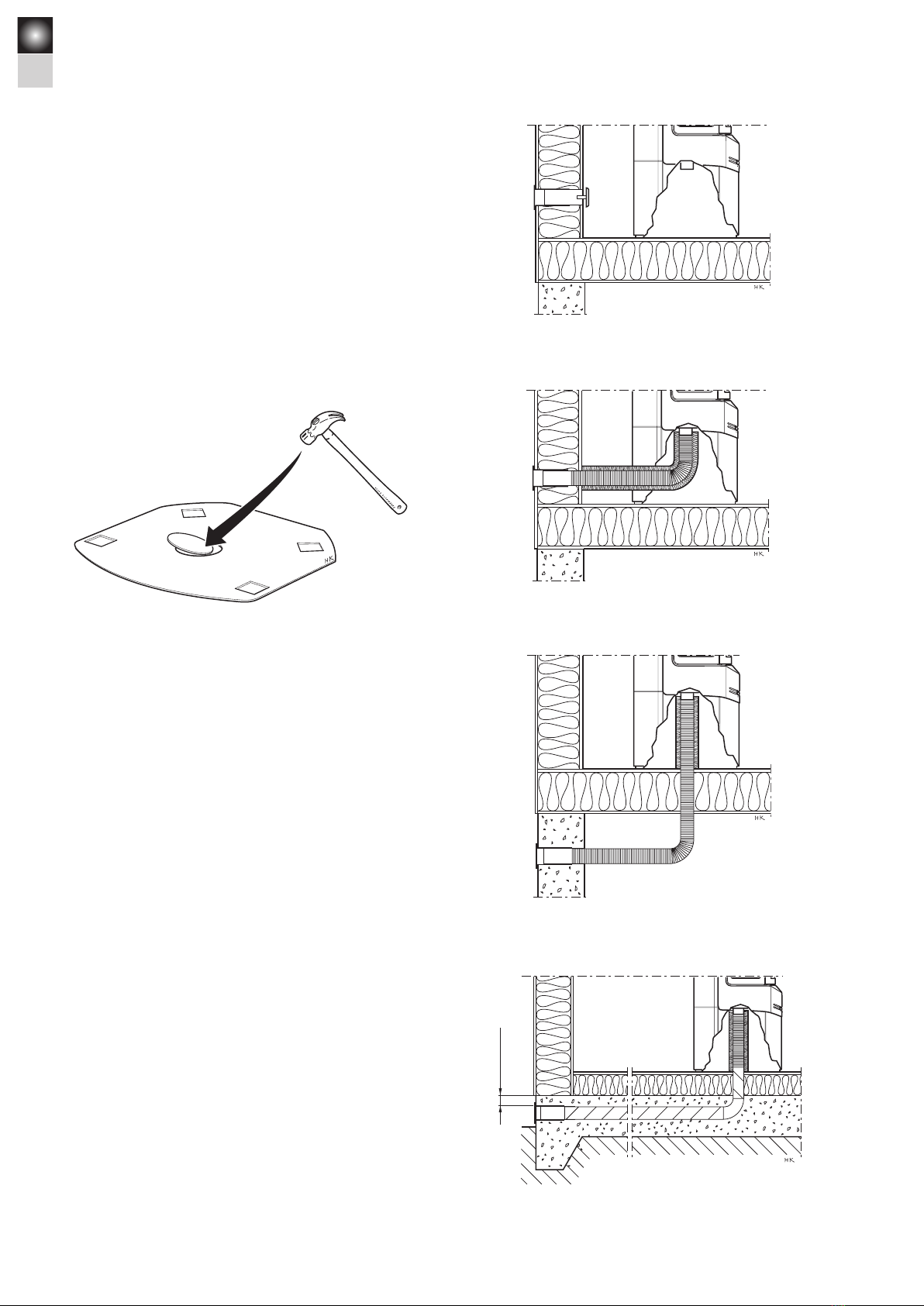
Make sure that there are no gaps around soot hatches and flue-
pipe connections.
Remember that the draught is reduced in flues with sharp bends
or horizontal sections. A horizontal flue length of up to 1.0 metre
is permissible, provided that the vertical flue is at least 5.0 met-
res in height.
It must be possible to clean the flue throughout its entire length,
and the soot hatches must be easily accessible.
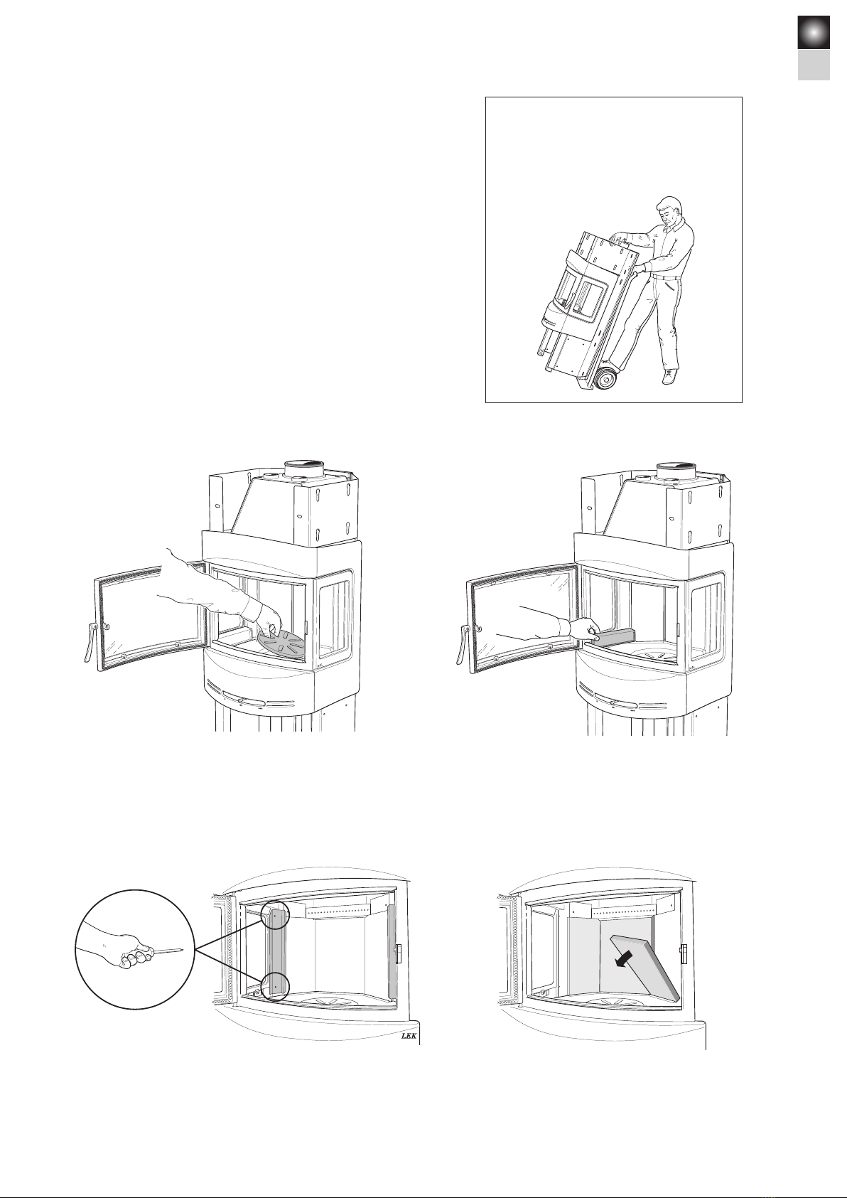
Fire bricks
Metal brackets
Grate disc
Cast-iron
fire-bed
Ash-pan
Log guard
Cover strips
Smoke baffle
53
GB
Stand the stove on a floor plate, ensuring that the stove is no closer to
the wall/ceiling than the minimum distances indicated in the diagrams
below. For stoves with a top flue connection to a steel chimney, please
refer to the assembly and installation instructions for the relevant
brand of chimney. Observe the minimum distances to combustible
materials prescribed by the manufacturers of the chimney.
Allow at least 1.0 metre from the stove door to any combus
tible part of
the building structure or interior fittings.
*349
494
*625
770
250
365
100
Air inlet Ø64
Combustible wall
* Requires extra glass panel.
50**
264
345
50**
665
Air inlet Ø64
Fire-retardant wall of
brick or concrete
552
276
1250
Air inlet Ø64
Min. 2100 to ceiling
Combustible roof
*100
240
*100
240
*312
452
*395
535
855
*715 Air inlet Ø64
Combustible wall
326**
50**
202
317
50
Air inlet Ø64
Fire-retardant wall of
brick or concrete
267
526
60
152
340522
1191
1083
372
Tilluftsstos Ø64
Utv. Ø150
A = height from floor to chimney connection
B = height from floor to centre of hole for rear flue
** To avoid any discoloration of
painted walls made of non-
combustible materials, we
recommend the same gap bet-
ween stove and wall as that for
walls in combustible materials.
A
B
Important!
An extra glass side panel with a heat-reflecting surface
must be fitted to stoves placed in a corner as shown
below, with 100 mm or 349 mm between the side of the
stove and a combustible side wall.
Air inlet Ø64 mm
Installation distances to walls and ceiling
54
GB
Indirect air supply through the external wall.
Through the floor and foundation slab.
Air supply
Combustion air for the stove can be supplied through a duct
directly from outside, or indirectly through a vent in the wall of
the room where the stove is installed.
The drawings on the right show various alternative methods of
supplying the stove with air.
The air duct connection on the stove has an external diameter of
64 mm.
The base-plate of the stove has a punched metal cover which can
be removed to permit the passage of an air supply hose.
Remove the partly punched metal cover with a hammer.
30 mm
To prevent condensation in air ducts which pass through heated
areas, the duct must be insulated with 30 mm of mineral wool
covered with a proprietary moisture seal (plastic vapour diffusion
retarder).
It is important to seal carefully around the duct where it passes
through the wall or floor. Use jointing compound. For ducts longer
than 1.0 metre, the diameter must be increased to 100 mm, and
the size of the vent increased correspondingly.
A 1.0 metre length of insulated ducting for combustion air is
available as an optional extra.
Through the external wall.
Through a suspended floor/wall-and-cavity foundation.
55
GB
L E K
Lift and transport the stove
as shown in these sketches.
Unpacking the stove
The cast-iron base may be removed to make it easier to lift and
carry the stove body.
Remove the cast-iron cover strips below the side windows.Remove the grate disc by lifting the edge furthest away from the
draught control bar.
Unscrew the metal brackets from the rear edge of the side win-
dows.
LEK
Remove the side bricks from the fire-box surround.
56
GB
Installing the smoke baffle
Raise the folded front edge of the smoke baffle up over the side
pegs. Then lift the rear edge of the baffle up over the vermiculite
holder.
IMPORTANT!
When correctly placed on top of the
supporting pegs, the baffle slopes
upwards from the back to the front.
Lift the cast-iron fire-bed at one side and tilt it so that it can be
removed through the door opening.
LEK
Remove the rear brick from the fire-box surround.
Stödtapp, sida Vermiculitehållare
LEK
Side peg Vermiculiteholder
57
GB
Top flue connection to a chimney
When installing the chimney, please refer to the manufacturer’s installation instructions.
Below we explain how to connect the chimney to the stove.
Top flue connection
Slide the flue base over the collar. Make sure that the seal round
the collar is not dislodged. If further sealing material is required,
heat-resistant sealant may be used.
Fit the connecting sleeve between the stove and the flue collar
in the wall. Make sure that the gasket does not work loose from
its position. Seal the joint between sleeve and collar with sealing
rope, or use heat-resistant sealant for a tighter seal.
Rear flue connection to masonry chimney
Mark out the centre of the hole to be made in the wall for a rear flue connection. Check the height to make sure that the hole aligns
with the chimney connection on the rear of the stove.
Important!
When connecting the stove to a top flue, make sure you fit the
hot-air vent and the screen before the chimney.
LEK
LEK
Gäller ej!
Make a hole at least 180 mm in diameter and then secure the flue collar in place in the wall using heat-proof mortar (not supplied). Allow
the mortar to dry before connecting the stove to the flue.
Stoves are supplied from the factory ready for
connecting to a top flue. To prepare the stove for
connection to a rear flue, the connecting collar and
covering cap need to change places.
Use a hammer to tap out the punched metal cover
in the stove’s rear panel. Cut away the metal cover
in the heat reflector with side-cutting pliers.
In the bag with these installation instructions
are two wing screws for the cover.
58
GB
Fitting the soapstone surround
Each tile is assigned a name and number, according to the scheme illustrated below. Certain tiles can
be used in more than one position and therefore have the same number. We recommend that the tiles
are fitted in the order described on the following pages.
Important! Handle soapstone with care. The tiles scratch easily and may be marked by oil and grease.
Övre frontsten
403357
Nedre frontsten
403353
Nedre vänster sidosten
403355
Vänster toppsten
403361
Höger toppsten
403360
Övre sidosten
403358
Övre ryggsten
403359
Mellanryggsten
403362
Nedre ryggsten
403356
Nedre höger sidosten
403354
Left top stone
403361
Upper front stone
403357
Lower front stone
403353
Lower left side stone
403355
Lower right side stone
403354
Lower rear stone
403356
Intermediate rear stone
403362
Upper rear stone
403359
Upper side stone
403358
Right top stone
403360