Nice LP1 Product manual

LP1-LP2
EN - Instructions and warnings
for the installer
IT - Istruzioni ed avvertenze per
l’installatore
FR - Instructions et recommandations
à l’attention de l’installateur
ES - Instrucciones y advertencias
para el instalador
DE - Anweisungen und Hinweise
für den Installateur
PL - Instrukcje i ostrzeżenia
dotyczące użytkowania
NL - Instructies en waarschuwingen
voor de installateur
Metal mass detector


EN
English - 1
Original instructions
ENGLISH
1–WARNINGS
• This instruction manual contains important information on safety during installation. It is
important to read all the instructions before proceeding with installation.
• Store this manual with care for future reference.
• This manual is destined solely for technical personnel qualified to perform installation.
No other information contained in this file may be considered of interest to the end user!
Additional information is available on: “www.niceforyou.com”.
• Use of the LP1 and LP2 for purposes other than those identified in these instructions is
forbidden; improper use may cause danger, injury or damage to property.
• Do not make changes to any part unless recommended in these instructions; opera-
tions of this kind can only cause malfunctioning; NICE shall not accept any liability for
damage caused by modified products.
• The manufacture of automation mechanisms for doors and gates is subject to the fol-
lowing standard: “EN 12453: Industrial, commercial and garage doors and gates -
Safety in use of power-operated doors”. Installation and connection of LP1 or LP2 with
the aim of producing an automation mechanism which does not meet the requirements
of this standard signifies negligence and deliberate abuse!
• LP1 and LP2 are not safety devices and must not be used as such.

EN
2- English
2–PRODUCT DESCRIPTION
AND INTENDED USE
LP1 and LP2 are metal mass detectors
which use a magnetic loop (loop detector)
and may be used for automatically open-
ing gates, doors, barrier gates, etc.
The model LP1 detector may be connect-
ed with a single loop and has one output,
while model LP2 may be connected with
two loops and has two outputs. The two
outputs may be independent (each loop
commands its own output) or they may be
combined to detect the vehicle’s direction
of movement (see point 3.3 for details).
Both models have an additional alarm out-
put, which is active during regular opera-
tion but is turned off in the event of a failure
or power failure.
3– INSTALLATION
Warnings
•Disconnect the power supply to the
system before performing any instal-
lation operations; if the system is
equipped with a buffer battery, it
must be disconnected.
1. Metal mass detector assembly on bar
Din 35 mm
2. Led L1: “Info”
3. Programming key P1: Mode
4. Programming key P2: Level
5. LCD display
6. Terminals for power supply, coil connec-
tion and outputs
6
6
4
3
5
2
1

EN
English - 3
•Install the product exclusively indoors or in a sheltered place; do not allow it to
get wet and protect it from excess moisture.
3.1 –Preliminary checks
Carefully check that the parameters for use correspond to the figures appearing in the
“Technical Features” section. In the event of doubt, do not use the product, and ask the
Nice technical assistance service for clarification.
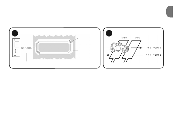
3.2 –Choice of coil geometry
The loop, constituting the detector’s sensitive element, is an inductor which, in combina-
tion with a condenser in the detection circuit, forms a type LC oscillator. The circuit’s res-
onance frequency depends on the loop inductance value. When a vehicle passes over
the loop, its metal parts (body, wheels, suspensions, etc.) change the inductance value
and therefore the frequency of the oscillator. The detector checks this frequency and
trips the relay when the variation exceeds the threshold specified for the established level
of sensitivity. To improve sensitivity and prevent false switching, it is essential to construct
the loop according to the following simple rules:
01. The rectangular loop is the simplest, most effective shape (fig. 1); it is suitable for
cars, trucks and buses. The 45° shape (fig. 2) is recommended for detecting motor-
cycles and bicycles, while the 8 shape (fig. 3) is for use in applications requiring
reduced sensitivity at the sides, such as when the loop is close to the gate.
02. Loop size must not exceed the size of the object to be detected; for instance, if the
car to be detected has an average width of 2 m, the loop must be 2 m wide.
03. If the loop is located near the gate or other moving metal parts, it is important to
comply with the minimum distance of 1 m between the loop and the moving parts.
04. Fixed metal parts close to the loop (such as concrete reinforcements, streetlight
poles, etc.) may reduce the detector’s sensitivity; make sure that this cannot hap-
pen by moving these parts, as a variation could result in false tripping.

EN
4- English
05. Install the LP1 or LP2 detector as close to the loop as possible; if possible, less than
10 m away. The cables connecting the loop must be kept separate from the power
cables and the output cables.
06. The loop may be made of ordinary insulated copper wire, preferably measuring 1.5
mm2.
07. The two wires at the start and end of the loop must be wound around themselves at
least 20 times per meter (fig. 4).
3.3 –Detecting direction of travel (LP2 only)
Detector LP2 may be connected with 2 separate loops, which may activate 2 completely
independent outputs, or, with appropriate programming, be used to determine direction
of travel.
Direction 1 ]2
If loop 1 is engaged first, when loop 2 is also engaged output 1 is triggered, remaining
active until loop 1 is no longer engaged. Loop 2 will never be triggered.
1 2 3

EN
English - 5
Direction 1 \2
If loop 2 is engaged first, when loop 1 is also engaged output 2 is triggered, remaining
active until loop 2 is no longer engaged. Loop 1 will never be triggered.
To obtain this function, both loops must be triggered, at least for a short time (fig. 5).
3.4 –Loop construction
01. After determining the position and geometry of the loop, a groove must be made in
the floor 5-8 mm wide and at least 30 mm deep; greater depths are required if the
installation surface is unstable and flexible under pressure; in asphalt for instance,
the cable requires greater protection because the deformation could damage it with
time. A 45° cut of the corners of the loop is recommended to improve mechanical
protection of the wire.
02. Clean the groove thoroughly then insert the wire, pressing it down as much as pos-
sible so that it settles towards the bottom.
03. The number of turns to make with the cable to produce the loop depends on its cir-
cumference; see Table 1.
The figures shown in the table are for cement or asphalt pavement; the presence of
metal reinforcement rods in the pavement will change the loop’s inductance. If you
4
Cable twisted
Loops
Groove
Pavement
5

EN
6- English
have any doubts regarding the loop you have made, measure inductance before
proceeding, as described in section “6 – Simulations and checks”. The loop is cor-
rect if inductance is between 80 and 300 µH.
04. To protect the loop against mechanical stress, it may be useful to insert a cord of
string or plastic in the groove. Seal the groove with bitumen or resin for outdoor use.
Pay attention to sealant temperature: it must not exceed the maximum temperature
for the electrical wire in the loop, which is normally 70°C.
05. Fig. 6 shows the correct loop composition.
4–PROGRAMMING
The programs described in this section refer to the LP1 with one loop. On the LP2 pro-
gramming of the second loop is available in sequence after the first loop.
Programming takes place using key P1 (Mode) which allows you to scroll through the
various functions available (on the LP2, first those for loop 1 and then those for loop 2).
Once you have reached a function, you may use P2 (Level) to choose the “value” to be
assigned to the function. Both lists of functions and values are “circular lists”; when the
list reaches its end, it starts scrolling from the beginning again.
TABLE 1
Loop Number of turns to
circumference make with the wire
Less than 3 m Request calculation
3-6 m 5
6-10 m 4
10-25 m 3
More than 25 m 2
(size best avoided)
6
Loops
Sealant
Groove
String

EN
English - 7
TABLE 2
Indications given by led L1
Red Calibration phase
when turned on
Green Regular operation
Red + green Programming under-
way
Flashing red Anomaly underway
Green Loop engaged
flashing
Flashing Simulation underway
red + green
TABLE 3
Indications on LCD display
Device Device
with 1 loop: with 2 loops:
LP1 LP2
1 1 2
1 2
Function
Loop 1,
output 1
Loop 2,
output 2
Example of
setting time
function
Example of
setting
parameter “h”

TABLE 4
Functions
Regular
operation Failure list No. 1 Failure list No. 2
Basic operation Gates Barriers
Time function Infinite (2) Delay at start
Time unit (2) 0.1 second 1 second
Time multiplier (2) 1Adjustable from 1 to 99
Sensitivity 6Adjustable from 1 (not
EN
8- English
P2 P2
P1
P1
P1
P1
P1
1
1
P1 1
1
1
1
1
1

Failure list No. 3 Failure list No. 4 Failure list No. 5
Inverted Direction
of travel
Loop 2:
active = 1(1)
off = 0
Delay at end Impulse at start Impulse at end
1 minute 1 hour —
very sensitive) to 9 (very sensitive)
EN
English - 9
P2 P2 P2
Function or level
active in factory
settings (or after
resetting)
Functions only
available on LP2
used with 2
loops
[1] If loop 2 is
turned off, you
may turn off the
corresponding
output (see func-
tion No. 8)
[2] If the “Time func-
tion” is set to
“infinite” then “-2
time units” and
“3- time multipli-
er” cannot be
programmed
1
1
1
12
1
1
1
2
...CONTINUED

Functions
Automatic
sensitivity Off On
Frequency F4 F1
Direction logic Both From 2 to 1
only
Configure Out 2 Out 2 = Off Out 2 = On
Power failure Off On
EN
10 - English
P1
P1
P1
P1
P1
2
1
1
1
2
1
1
1
P2 P2

— — —
F2 F3 —
From 1 to 2
only — —
— — —
— — —
EN
English - 11
Function or level
active in factory
settings (or after
resetting)
Functions only
available on LP2
used with 2
loops
1 1
1
P2 P2 P2

Code E
301 E
302 E
311 E
312
Error 1 high 2 high 1 low 2 low
Code E
001 E
002 E
011 E
012 E
101 E
201
Error Loop 1
interrupted Loop 2
interrupted Loop 1 in
short circuit Loop 1 in
short circuit
Power
supply too
low
Error in
memory
EN
A - Regular operation: the standard selection during regular operation.
In the event of a failure (in addition to led L1 which starts flashing red), the failure code will
appear on the display. The list of failures may be viewed even after the problem has been
solved by pressing P2. To delete the list, simply press P2 for at least 2 sec.
Loop inductance value

EN
English - 13
0 - Basic function: allows you to select the type of operation, or the behavior of the out-
put relay in relation to various statuses, on the basis of the following Table 5.
TABLE 5
No
power Turning
on Loops 1
and 2
free
Loop 1
engaged Loops 1
and 2
engaged
Loop 1
free and
loop 2
engaged
Loops 1
and 2
free
Fault
Gates
Barriers
Inverted
Direction
of
movement
(12)
Out 1
Out 2
Allarm
Out 1
Out 2
Allarm
Out 1
Out 2
Allarm
Out 1
Out 2
Allarm

TABLE 6
The relay faithfully follows loop engagement without
any timing
The relay is energized after a delay in loop engagement
The relay is energized when the loop is engaged and
de-energized after the delay following freeing of the
loop
The relay is energized when the loop is engaged and
de-energized after the delay, even if the loop is still
engaged
The relay is energized when the loop is freed for the
specified delay time
EN
14 - English
1 - Time function: allows you to select the type of timing linked with the relay output, on
the basis of the following Table 6.
2 - Time unit: selects the basic unit for timing.
3 - Time multiplier: selects the multiplier for timing time; if, for example, the unit of time is
“1 second” and the multiplier is 3, then timing will take 3 seconds.
Infinite
Impulse at end
Delay at start
Impulse at start
Delay at end

4 - Sensitivity: allows you to select the sensitivity of the reading, between 1 (not very sen-
sitive) and 9 (very sensitive). The regulation range may be reduced as a result of use of giv-
en frequencies or in the case of very low loop inductance (few turns).
5 - Automatic sensitivity: “automatic sensitivity” is normally turned on to permit correct
detection of truck trailers along their entire length, as the front part (driver’s cabin) is rela-
tively close to the ground and easy to detect while the trailer is higher and hard to detect
without greater sensitivity.
6 - Frequency: to prevent interference between nearby detectors, it is possible to change
the frequency band; frequency may be modified within the following limits of Table 7.
7 - Direction logic: when detection of the “direction of travel” is activated (on LP2 only), it
is possible that detection may take place in both directions or in just one direction.
8 - Configure Out 2: If loop 2 is turned off, you may turn off the corresponding output.
9 - Power failure: used to turn on protection against power failures. This function saves
the present conditions before the power cuts out. When the power supply returns, the
detector compares the saved information and activates the outputs according to whether
the loop is active or not.
If this function is not active, the detector will be “recalibrated” when it comes back on,
acquiring data at that specific moment in time.
TABLE 7
Frequency Sensitivity Loop inductance
F1 1÷7
150÷300
(1000)
F2 1÷7
< 150 µHF3 1÷7
F4 1÷9 < 80µH
EN
English - 15

EN
16 - English
This function can only be used if the “Basic function” is set to “Barriers” or to “Inverted”, or
the “Time function” is set to “Infinite”. Sensitivity levels can only be controlled between 1
and 5. Lastly, function “5-Automatic sensitivity” must be disabled.
5–DELETING PROGRAMMING AND RECALIBRATING
It is possible to delete all the programming and reset the detector to the factor settings.
Total delete: hold the P1 and P2 keys down for at least 8 seconds.
If changes are made to the environment around the loops, it may be useful to recalibrate it.
Recalibration: press P1 for at least 2 seconds.
6–SIMULATIONS AND VERIFICATIONS
The detectors have a simulation mode which permits activation of various outputs and
measurement of loop inductance. In “simulation” mode the loops must be properly con-
nected.
To turn on “simulation” mode, hold the P1 and P2 keys down for at least 2 seconds. As
during programming, you may then press P1 to scroll among different types of simulation;
select the value to be simulated while holding P2 down; refer to the Table 8.
Both lists of functions and values are “circular lists”; when the list reaches its end, it starts
scrolling from the beginning again. To exit simulation mode, hold P1 down for at least 2
seconds.

TABLE 8
Functions
Turning on
outputs
with associated
time function
Turning
off
output 1
Turning
on
output 1
Turning
off
output 2
Turning
on
output 2
Turning output
on immediately Turning
off
output 1
Turning
on
output 1
Turning
off
output 2
Turning
on
output 2
Turning on
alarm output Turning
off
alarm
output
Turning
on
alarm
output — —
Measurement
of inductance
of loop 1
Indicates
the in-
ductance
value of loop 1
in µH
———
Measurement
of inductance
of loop 2
Indicates
the in-
ductance
value of loop 2
in µH
———
EN
English - 17
1
1
2
2
1
1
2
2
2
2
Functions only available on LP2 used with 2 loops
P2 P2 P2 P2
P1
P1
P1
P1
P1

EN
18 - English
DISPOSING OF THE PRODUCT
This product is an integral part of the automation mechanism and must be disposed
of along with it.
As in installation operations, at the end of the product’s lifespan, disposal operations must
be performed by qualified personnel. The product is made of various types of materials:
some of them may be recycled, while others cannot. Find out about recycling and disposal
systems in use in your area for this product category.
Important! – some parts of the product may contain polluting or hazardous substances
which, if released into the environment, may have damaging effects on the environment or
on human health.
As indicated by the symbol appearing here, the product may not be disposed
of with other household wastes. Dispose of it separately in accordance with
the methods required under the regulations in effect in your area, or give it
back to the seller when you purchase an equivalent new product.
Important! – local regulations may provide for heavy fines if the product is
disposed of inappropriately.
This manual suits for next models
1
Table of contents
Languages: