NiceRF SV652 User manual

www.nicerf.com SV652
1. Overview
SV652 is an Industrial class & highly-integrated RF transceiver module, which adopts the high
performance Si4432 from Silicon Labs and industrial micro-controller. TTL / 232 /485 can be chosen
corresponding to SV652-TTL / SV652-232 / SV652-485. SV652 has good sensitivity and 500mW
output power to achieve long RF range and reliable RF communication. To avoid the interference,
SV652 provides 40 frequency channels and configurable Net ID. SV652 is flexible but easy to use , it
comes with many parameters, such as: frequency, data rate, output power, Net ID, Node ID. Users
can configure the parameters through PC or customer’s own device.
2. Feature
n433/470/868/915 MHz
(Customizable240-930 MHZ)
nIndustrial class
n40 channels
n4 bytes Net ID & 2 bytes Node ID
nSeries Data Rate: 1200 ~ 115200 bps
nAir Data Rate: 1200 ~ 115200 bps
nGFSK modulation
nRSSI
nInterface: TTL/RS232/RS485
nAntenna matching automatically
nBi-directional & Half duplex
nSensitivity: -121 dBm
nMax output power: 500 mW (+27 dBm)
nWorking voltage: 3.3 ~ 6.5 V
nWorking temperature: -40 ~ +85 °C
nWeight: 47 g
nParameters save automatically
3. Application
nRemote control telemetry
nSecurity system
nIndustrial data acquisition
nHome automation
nWireless data communication
nAccess system
nRobot control
nWireless PC peripherals
4. Block Diagram

www.nicerf.com SV652
5. Electrical Characteristics
Note: High quality 3.3V LDO is integrated, and Pin CS / SET is 3.3V interface. TXD/RXD is also
3.3V for SV652-TTL
Parameters Min. Typ. Max. Unit Condition
Working condition
Voltage range 3.3 5.0 6.5 V
Operating Temperature
-40 25 +85 ℃
Current consumption
Rx current
25 mA TTL level
34 mA 485 level
32.7 mA 232 level
Tx current 350 mA @27dBm
Sleep current <5 uA @TTL level
RF parameters
Frequency range
414.92
433.92 453.92 MHZ @433MHZ
470.92
470.92 509.92 MHZ @470MHZ
849.92
868.92 888.92 MHZ @868MHZ
895.92
914.92 934.92 MHZ @915MHZ
Data rate 1.2 9.6 115.2 Kbps GFSK
Output power 20 / +27 dBm
Sensitivity -121 dBm @1.2kbps
6. Operation
1) Power on Reset
After powered on reset, the TX LED (Red) and RX LED (Blue) will blink 3 times. The total reset
time is around 2s, as below:
Note:Contact us to customize if you want to shorten the POR time.

www.nicerf.com SV652
2) Sleep mode
After Power on Reset, the module enters into sleep mode when CS pin is pulled low. In this mode,
the current consumption is very small. In Sleep mode, the module can’t do any communication and
cant’ be set even Set Pin is pulled low. All the parameters will be kept unchanged in Sleep mode.
User can wake up the module by pulling high the CS Pin.
3) Working Mode
The CS and SET Pin is internally pulled up. Pull CS pin high or leave it open will make SV652 enter
into working mode.
Sleep mode Working mode Setting mode
CS 0 1* 1*
SET X 1* 0
★ 1*: connected to 3.3V or leave open. X: don’t care
In working mode, SV652 stay in receiving mode and wait for the series signal and RF signal.
SV652 can connect with any device which is standard 232/485/TTL interface.
When series signal comes, SV652 will check the input series signal if there is any error, and then
transmit the received data out via RF automatically if no errors found.
When RF signal comes, SV652 will check the RF signal input if there is any error, and then transmit
the received data out via series port automatically if no error found.
When one packet is transmitted successfully, the Red LED will blink once.
When one packet is received and verified with no problem, the Blue LED will blink once.
The easiest way to test the module is using computer. The corresponding PC software is “Series
Debugging assistant” can be downloaded at : http://www.nicerf.com/downpwd.aspx?id=102, the
password for download is “nicerf”. User can use our USB bridge board (SU108 –TTL / SU108-232
/SU108-485) to connect SV652 with computer.
The GUI of the software is as below:

www.nicerf.com SV652
★To ensure the stability of communication, please notice the following tips:
a) Parameter matching
The series parameter between the device and SV652 should be same,
RF parameters should be same in Tx and Rx.
The Net ID should be same in Tx and Rx.
b) Delay Time
Data delay is exist between series input of the transmitter and series output of the receiver. This
Delay Time is different from the series data rate, RF data rate and payload length. Detailed value is as
below:
Speed rate 1200
2400
4800
9600
14400
19200
38400
57600
76800
115200
1byte
transceiver
time(ms) 140
70
37
21
15
13
9
8
8
7
56bytes
transceiver
time(ms) 945
475
241
124
85
65
36
26
21
16
c) Long package transmission
One packet more than 200 bytes is a long package. The RF data should be set higher than series data

www.nicerf.com SV652
for long package transmission. The distance will be shorter with higher RF data rate.
4) Setting mode
In working mode, pull low the SET pin to force SV652 into setting mode. When using USB bridge
board, simply put on the short cap to enter into setting mode.
In setting mode, both blue and red LED will light on, shown as below:
In setting mode, users can set the parameters by PC software or customer’s own device. The
parameters will be stored and keep unchanged even powered off.
Step to set the module with PC:
uDownload the PC software at: http://www.nicerf.com/downpwd.aspx?id=103, the password is
“nicerf”.
uDownload the USB driver at: http://www.nicerf.com/downpwd.aspx?id=105, the password is
“nicerf”.
uInstall the PC software and USB driver into computer.
uConnect RF module with USB Bridge, put on the short cap, and insert into the PC.
uOpen the PC software, the GUI is as below:
Select the right COM port and click “OPEN” button, all the parameters stored in the module will be
read out and display, the status bar will appear the message “Device Found”.
If SV652 hasn’t connected with PC correctly or wrong COM port is chosen, the status bar will show
“Device Not Found”.

www.nicerf.com SV652
Note:About the Net ID and Node ID
After connected with PC correctly, all the parameters can be set freely including Net ID and Node ID.
The Net ID is the group name for transmitter and receiver, all the transmitter and receiver with the same Net ID can
communicate with each other. The only exception is 0000. When the Net ID is set as 0000, it can receive the signal
of all the transmitter even the Net ID is not 0000.
The Node ID can be thought as the name of the module. Each module can be set with one Node ID. The Node can
set and read out freely. The Node ID can be used in the application which the receiver should identify who is the
transmitter. User can read out the Node ID of the module, and add the Node ID into the payload, then in Rx side, it
can identify who is the transmitter.
5) Communication Protocol
Besides PC, user can set all the parameters by their own device. The communication protocol is as
www.nicerf.com SV652
below:
Baud rate=9600 bps; Data bit=8 bits Stop bit:1 Parity bit: none
a) Command : Read module name and version:
Instruction format: AA FAAA
Return value is:“SV652_VERx.x\r\n”
For example:
Instruction : AA FAAA
Return: SV652_Ver4.6 \r\n.
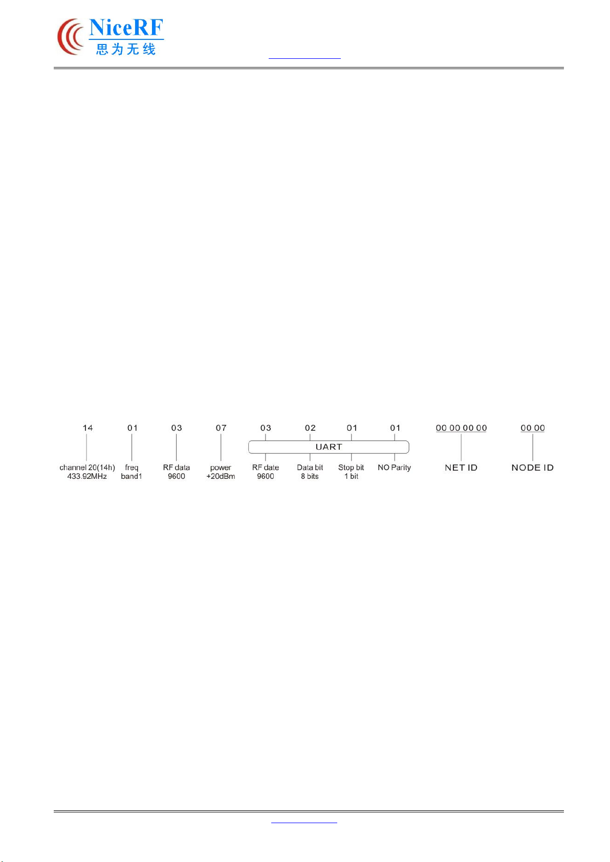
b) Command: Read out all the parameters:
Instruction format: AA FA 01
The return value in turn is:
RF channel / RF band / RF data rate / RF power / Serial data rate / Series Data bit / Series Stop bit /
Series Parity bit / NET ID / NODE ID /\r\n
For example, when module is default setting, the return are as below:
c) Command : Reset to default setting
Instruction format: AA FA 02
The return value in turn is: "OK \ r \ n" or "ERROR \ r \ n"
After this command , the module will reset to default setting ,which is
Frequency : Tx = Rx = CH20 = 433.92 MHz (Band = 433MHz)
RF data rate: Tx = Rx=9600 bps
RF power= 7 (Max output)
Serial: baud rate = 9600 bps Data bit= 8 Bits Stop bit = 1 Bits Parity bit=None
NET ID = 00 00 00 00 NODE ID = 00 00
d) Command: Set the group parameters
Length of the command is 17 bytes, set 14 bytes of the parameters into the module, the format as
follows:

www.nicerf.com SV652
Instruction format: AA FA 03 RF Channel / RF Band / RF Rate / RF Power / Serial transmission date
/ data bits / stop bits / parity / NET ID / NODE ID
The return is: "OK \ r \ n" or "ERROR \ r \ n"
6) RSSI index
The RSSI index value can only be read out in setting mode. The real time RSSI index is updated by
incoming signal.
Instructions format : AA FA 04
Return:RSSI index\00\r\n (hexadecimal,range:0x00~0xff)
RSSI index range : 00 ~ FFh
For example:
Instruction format: AA FA 04
Return: 32 00 \r\n.
Relationship between RSSI and input power is as below
7) Parameters Description:
a) RF Channel = RF Frequency
Each frequency band is divided into 40 channels, user can select one of the 40 channels to use. The
corresponding frequency is as below, Also we can customized the specified frequency which is not in
the table.

www.nicerf.com SV652
b) Working Band
The working band is as below
Parameter 01 02 03 04
Frequency
433 MHz 470 MHz 868 MHz 915 MHz
414.92 ~ 453.92
470.92 ~ 509.92
849.92 ~ 888.92
895.92 ~ 934.92
Note:Changing working band is not suggested
c) RF data rate
The RF data rate is as below :
Parameter 0 1 2 3 4 5 6 7 8 9
TX/RX
rate(bps) 1200 2400 4800 9600 14400
19200
38400
57600
76800
115200
d) RF output power
The output power is as below :

www.nicerf.com SV652
Set level 0 1 2 3 4 5 6 7
TX/RX
power 24dBm
25dBm
26dBm
+27dBm
+27dBm
+28dBm
+28dBm
+28dBm
e) Serial baud rate
Series data rate is as below: .
Parameter 0 1 2 3 4 5 6 7 8 9
Serial
rate(bps) 1200 2400 4800 9600 14400
19200
38400
57600
76800
115200
f) Serial data bit
Series data bit is as below:
Parameter 1 2 3
Data Bits 7 bits 8 bits 9 bits
g) Serial stop bit
Series stop bit is as below:
Parameter 1 2
Stop bit 1 bits 2 bits
h) Serial parity
Series Parity bit is as below:
Parameter 1 2 3
Parity bit No Odd Even
i) NET ID:
The Net ID is 4 bytes, and range from 00 00 00 00 to FF FF FF FF
Note: if the modules’ NET ID setting are different, then they can't communicate with each other
except when the Net ID = 0000, it will receive all the message despite the Net ID is difference.
j) NODE ID
The Node ID is 2 bytes, range from 00 00 to FF FF.
7. Application circuit
The typical schematic circuit is as below:
Note: The ground pin of the module and device should be connected together.

www.nicerf.com SV652
Typical application::
8. Pin definition
Pin No.
Definition
Description
1 VCC Connected to the positive power supply (typical 5V)
2 GND Connected to ground
3 TXD TXD of the module and connect to external RXD
4 RXD RXD of the module and connect to external TXD
5 SET Configuration mode enable (low to enter into the setting
mode, leave open or
connect high level to exit setting
mode) Valid when CS Pin is high or leave
open.
6 CS Module working Enable(Pull Low to make the module enter into
sleep mode, Leave open or connect high level make the module e
nter into
normal working mode)
www.nicerf.com SV652
9. Accessories
1) Antenna
The antenna is very important for RF communication. We have many kinds of antenna for customer
to choose, please contact the corresponding sales engineer for help.
★Tips for antenna:
ØDon’t close to the ground, metal, magnet, big current;
ØIf you are using the sucker antenna, pull the wire as straight as possible, the sucker foundation
should stick with metal
2) USB bridge board
There are 3 type of USB bridge, which is SU108-TTL/ SU108-232 / SU108-485.SU108 -TTL is for
TTL Interface, SU108-232 is for 232 Interface, SU108 - 485 is for 485 Interface. User should select
the right USB bridge board corresponding to the RF module.
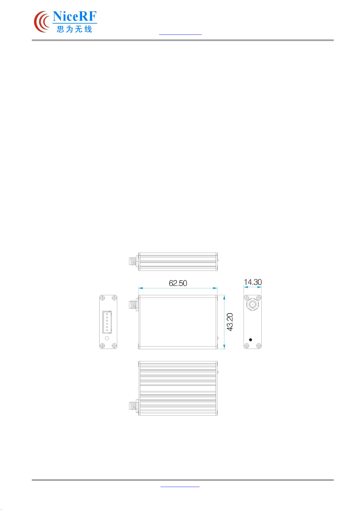
10. Mechanical dimension

www.nicerf.com SV652
11. Order information
For example:
If the customer needs 433MHZ band with 232 Interface then part number of released order shall be:
SV652-232-433
Product Name Description
SV652-TTL- 433 433MHZ,TTL interface
SV652-232- 433 433MHZ,232 interface
SV652-485- 433 433MHZ,485 interface
SV652-TTL- 470 470MHZ,TTL interface
SV652-232- 470 470MHZ,232 interface
SV652-485- 470 470MHZ,485 interface
SV652-TTL- 868 868MHZ,TTL interface
SV652-232- 868 868MHZ,232 interface
SV652- 485- 868 868MHZ,485 interface
SV652-TTL- 915 915MHZ,TTL interface
SV652-232- 915 915MHZ,232 interface
SV652-485 -915 915MHZ,485 interface
This manual suits for next models
12
Table of contents
Other NiceRF Transceiver manuals


