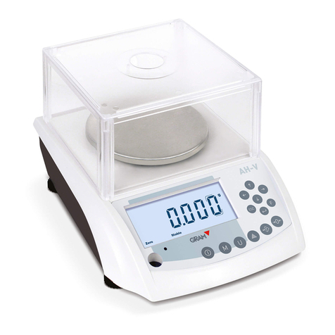
Nicol Scales & Measurement Sartorius Combics CAPXS Series User manual

98648-010-95
Operating Instructions
Sartorius Combics
CAPXS.. Models
Stainless Steel Weighing Platforms for
Use in Hazardous Areas/Locations

2
Contents
2 Symbols
2 Intended Use
3 Warning and Safety Information
3 Warranty
4 Installation Instructions
6 Installation
9 Care and Maintenance
10 Use of in Legal Metrology in the EU (or EEA)
10 Declarations of Conformity
11 Accessories
12 Zertifikates
The following symbols are used in these instructions:
§indicates required steps
$indicates steps required only under certain conditions
> describes what happens after you have performed a certain
step
– indicates an item in a list
!indicates a hazard
Make sure you observe the following warning and safety
information in its entirety during installation and operation,
as well as while performing maintenance and repair work
on the equipment. It is important that all personnel using
the Combics equipment understand this information, and
have access to it at all times.
Furthermore, the warning and safety information supplied
with any electrical equipment connected, such as the
indicator, must be observed as well. The warning and safety
information can be supplemented by the equipment
operator. Make sure all operating personnel are informed of
any additions to these instructions.
Intended Use
The weighing platform and the connected indicator
are intended exclusively for use in weighing.

3
Warning and Safety Information
The weighing platform meets the
requirements for Group II, Category 2
equipment in accordance with EC Directive
94/9/EC and bears the designation
hII 2 GD EEx ib IIC T4...T6 T135...155°C in
accordance with KEMA EC type-examination
certificate 02ATEX1010X.
Furthermore, the weighing platform meets
the EC Directives for electromagnetic
compatibility (see the Declaration of
Conformity). Improper use or handling,
however, can result in damage and/or injury.
- The weighing platform can be operated
indoors or outdoors. This weighing platform
must not be used in the medical industry (as
a medicinal product).
- The weighing platform may be used in Zone
1, 2, 21 or 22 hazardous areas or Class 1,
Division 1 or 2 hazardous locations (gas and
dust explosion hazards). Please make sure
the currently valid regulations and guidelines
for installing equipment in the hazardous
areas/locations listed above (e.g., EN60079-
14 or, in Germany, ElexV) are strictly
observed. Whether the equipment can be
used in a given area containing potentially
explosive agents must be checked on a case-
by-case basis.
- The weighing platform may be used and
operated by qualified personnel only. The
permitted uses of the weighing platform are
specified in the type-examination certificate.
- Do not expose the weighing platform to
aggressive chemical vapors or to extreme
temperatures, moisture, shocks, or vibration.
The permissible operating temperature range
during operation is -10°C to 40°C (14°F to
104°F).
- If you use suction lifting equipment to lift
the load plate, always wear gloves, hard-toed
safety boots and protective clothing.
Warning: Danger of personal injury! Only
reliable personnel who are qualified to
perform such work are allowed to use
suction lifting equipment.
- Suspension points are designated on models
of 1000 x 1000 mm and larger. If you need
to transport or lift the scale or load plate
using a crane, do not stand underneath the
suspended scale or load plate.
- Make sure to observe the applicable safety
rules and regulations for the prevention of
accidents.
- Do not damage the junction box or the load
cells during transport.
- Installation in a Zone 1, 2, 21 or 22
hazardous area or Class 1, Division 1 or 2
hazardous location must be performed by a
trained technician who is familiar with the
assembly and operation of the equipment, as
well as with the procedure for putting the
system into operation. Furthermore, the
trained technician must have the required
qualifications and must be familiar with the
relevant guidelines and regulations. If you
need assistance, contact your Sartorius dealer
or the Sartorius Service Center. Any
installation work that does not conform to
the instructions in this manual will result in
forfeiture of all claims under the
manufacturer’s warranty. Be sure to observe
all restrictions listed in the type-examination
certificate. Operating the weighing platform
beyond the limits imposed by these
restrictions is not permitted, and is
considered use of the equipment for other
than its intended purpose.
- Have the equipment inspected at appropriate
intervals for correct functioning and safety
by a trained technician.
- The junction box may be opened only by
authorized service technicians who have
been trained by Sartorius and who follow
Sartorius’ standard operating procedures for
maintenance and repair work.
- Always make sure the weighing platform is
disconnected from AC power before
performing any installation, cleaning,
maintenance or repair work. If the
equipment housing is opened by anyone
other than persons authorized by Sartorius,
all claims under the manufacturer’s warranty
are forfeited. Use only original Sartorius
spare parts.
- Handle the equipment as specified in EN
60529 (in Germany: VDE 0470 Part 1) in
accordance with its protection (IP) rating.
The protection rating of the weighing
platform is IP67. Do not damage the IP
protection when cleaning the equipment.
The IP protection rating is ensured only if
the rubber gasket is installed on the junction
box and all cable gland screw fasteners are
connected securely. Any installation work
that does not conform to the instructions in
this manual will result in forfeiture of all
claims under the manufacturer’s warranty.
- If you use cables purchased from another
manufacturer, check the pin assignments.
Before connecting the cable to Sartorius
equipment, check the pin assignments in the
cable against those specified by Sartorius
and disconnect any wires that are assigned
differently. The operator shall be solely
responsible for any damage or injuries that
occur when using cables not supplied by
Sartorius.
- When using the weighing platform in
hazardous areas/locations, make sure there is
no current or voltage in the equipment
before connecting or disconnecting current-
carrying cables to or from the platform.
Disconnect the platform from AC power
before connecting or disconnecting
cables.
- Avoid exposing the weighing platform to
static electricity; be sure to connect the
equipotential bonding conductor to the
junction box.
- Disconnecting equipotential bonding
conductors is not permitted.
- If you see any indication that the
weighing platform cannot be operated
safely (for example, due to damage), turn
off the platform and lock it in a secure
place so that it cannot be used for the
time being. Observe the relevant safety
precautions and inform personnel as
required.
- The casing on all connecting cables, as
well as the casing on wires inside the
equipment housing, is made of PVC.
Chemicals that corrode these materials
must be kept away from these cables.
- Make sure the weighing instrument is not
exposed to substances that release
chlorine ions at the place of use. If such
exposure cannot be ruled out, the
operator is responsible for establishing
and observing appropriate safety
precautions, to be checked at regular
intervals for continued effectiveness.
- The load cells installed are manufactured
by Global Weighing Technologies; type
designations: 011299/... through
011311/...; EC type-examination
certificate no. PTB 02 ATEX 2061. The
designation code is:
hII 2 G EEx ia IIC T4/T6.
The specifications are listed in the EC
type-examination certificate. The load
cell may be used and operated by
qualified personnel only. The permissible
use of the equipment is defined by the
equipment specifications and the relevant
safety regulations. Operating the load
cell beyond the specifications listed in
the type-approval certificate is not
permitted, and is considered use of the
equipment for other than its intended
purpose. All restrictions listed in the
type-examination certificate must be
strictly observed.
Warranty
Do not miss out on the benefits of our
full warranty. Please contact your local
Sartorius office or dealer for further
information. If available, complete the
warranty registration card, indicating the
date of installation, and return the card
to your Sartorius office or dealer.

4
Installation Instructions
§Prepare a suitable place of installation for the weighing platform. The place of
installation should be dry, level and even. The allowable operating temperature range
is -10°C to +40° (14°F to 104°F). The permissible load that can be carried by the
chosen working surface must be sufficient for both the weighing platform and any
load placed on the platform.
If you need to use the weighing platform in areas exposed to heavy traffic (e.g., forklift
trucks), you should install a protective frame, consisting of angular braces, around the
weighing platform.
Do not expose the weighing platform unnecessarily to extreme temperatures, moisture,
shocks, or vibration that could result in damage.
§The air bubble must be centered within the circle on the level indicator.
§Level the weighing platform using the leveling feet as described below:
§Check to ensure that all leveling feet rest securely on the work surface.
> Each of the leveling feet must support an equal load.
§Loosen the lock nuts on the leveling feet using a 19-mm open-end wrench (spanner).
> Adjusting the leveling feet:
To raise the weighing platform, extend the leveling feet (turn clockwise).
To lower the weighing platform, retract the leveling feet (turn counterclockwise .
§After leveling the weighing platform, retighten the lock nuts securely as described
below:
Low-capacity platforms (1 load cell): tighten the lockouts against the platform frame;
high-capacity platforms (4 load cells): tighten the lock nuts against the platform feet.
§If the weighing platform is in a hazardous area/location, it must be grounded (i.e., an
equipotential bonding conductor must be connected). This connection should be made
by a trained technician.
All Combics weighing platforms are equipped with a connector for the grounding
conductor.
This is located either below the load pan, on the junction box, or on the lower frame of
the weighing platform. The position is marked in each case by the symbol shown here,
indicating the grounding (earthing) connection.
The grounding conductor is connected to a threaded bolt or terminal screw, or a bore
hole is provided. If a bore hole is provided, use a stainless steel screw and nut to
connect the grounding conductor. Use of a tooth lock washer is recommended, to
prevent the screw from coming loose. The wire used for the grounding conductor
should have a cross-sectional diameter of at least 4 mm2 , with a suitable ring lug
attached.
Connect all equipment, including peripheral devices, to the equipotential bonding
conductor

5
Conditions for Installation
Before putting the equipment into operation, it is important to make sure that
the cable of the power supply is correctly connected to the power outlet
(mains supply). All equipment must be connected to the equipotential
bonding conductor via grounding cable (not included in delivery) connected
to the grounding terminals on each device.
The dimensions of the grounding cable are specified in national regulations
for electrical installations. Installation must be performed by a trained
technician in accordance with national regulations and generally
acknowledged rules of engineering .
Use only cabling and extensions approved by Sartorius, as these are made in
accordance with the restrictions on permissible cable lengths imposed by both
the capacitance and inductivity values (see the „Annex to EC Type-
Examination Certificate“ in the operating instructions) and the requirements
for electromagnetic compatibility.
Before putting the weighing system into operation for the first time, make
sure there is no hazard of explosion present at the place of installation. If
there is any indication that the equipment does not function properly (e.g.,
display remains blank, or no display backlighting) due to damage during
transport, disconnect the equipment from power and notify your nearest
Sartorius Service Center.
The weighing platform specifications for Ui, Li, Pi, Ta, temperature class, Ci,
and Li are listed in the EC type-examination certificate. This certificate also
specifies the indicator models that can be used with these platforms. These
specifications must be taken into account when connecting an indicator to
the platform. Ci and Li values apply to weighing platforms with a 3-m cable
for connecting the indicator. (See also the „Certificate of Proof of Intrinsic
Safety“ in the appendix to this manual.).
The explosion-protected weighing system must be installed in accordance with
acknowledged rules of engineering. These include national and international
laws and regulations, such as EN 60079-14 and EN 5281-1-2, for example.
In particular, the conditions described under Item 17 of the KEMA EC type-
examination certificate, „Special Conditions for Safe Use“, must be observed.
Furthermore, national regulations for accident prevention and environmental
protection must be observed at all times.
Before the platform is operated in a hazardous area/location, it must be
inspected either by a certified electrician or under the guidance and
supervision of a certified electrician to make sure that the weighing system
complies with the applicable regulations (in Germany, Section 12 of the
ElexV). Determine whether the installation must be registered with technical
inspection authorities (such as the trade board) in your country. Regular
inspections must also be performed on the system during operation. The
system should be inspected at intervals short enough to permit the prevention
or early detection of defects that arise as a result of normal wear and tear.
The longest permissible interval period is 3 years. Other conditions and
standards that regulate the installation and operation of the equipment and
are applicable in your country must be met as well. When performing
inspections, generally acknowledged rules of engineering relevant to these
conditions must also be applied.
If the terminal housing is opened by anyone other than persons authorized by
Sartorius, or if the terminal is installed or operated incorrectly, this will result
in forfeiture of the approval for use in the stated hazardous area(s)/location(s)
and of all claims under the manufacturer’s warranty.

6
Installation
§Connect the cable of the weighing platform to a suitable indicator, such as the FCT01-X
from Sartorius.
Note:
The cable gland on Sartorius indicators is installed at the factory. Please use extreme
caution when performing any work on the equipment that affects this cable gland.
§Remove the casing from a length of the cable end and install the cable as follows:
– Remove the screw fastener from the cable gland and slide it over the end of the cable.
– Remove the casing from a section of the cable end (see illustration). The shielding (1)
must have contact with the clamps (2). Fold back 3 to 4 mm of the shielding so that it
overlaps the O-ring (see illustration).
– Expose approximately 15 cm (4 inches) of the wires (3) for connection within the
terminal.
– Thread the cable through the cable gland.
– Make sure the shielding is in contact with the clamps. The shielding supplies the
grounding connection.
– Replace the screw fastener and tighten it securely.
§Connect the wire ends to the terminal strip:
– Remove the casing from a section of the cable end. Expose enough of the wires in the
cable for installation.
– Remove the casing from approx. 1 cm (0.5 in.) of the wires and affix ferrules to the
wire ends.
– Slide the enclosed protective sleeve over all the wires down to the cable gland, so that
no more than 5 cm of the wires is exposed between the end of the sleeve and the
terminal strip.
– Attach the wires securely to the screw terminals (blue = positive, brown or black =
negative)
Color Codes in the Weighing Platform Connecting Cable, Model CAPXS..
No. Signal des. Meaning Color of wire casing
1 BR_POS Bridge supply voltage (+) blue
2 SENSE_POS Sense (+) green
Bridge supply voltage
3 OUT_POS Measuring voltage positive white
4 OUT_NEG Measuring voltage (-) red
5 SENSE_NEG Sense (-) gray
Bridge supply voltage
6 BR_NEG Bridge supply voltage (-) black or brown
§Use a screwdriver to tighten the terminal screws.
Note on connecting the FCT01-X:
The bridge supply voltages are protected by 62mA fuses. To prevent the fuses
from reacting if wires are incorrectly connected, resistors between pin 1 and
pin 6, between pin 1 and the housing and between pin 6 and the housing must
measure greater than 140 ohms. Low-ohm connections are also required between
pins 1 and 2 and between pins 5 and 6.

7
Key to Model Codes (CAPX ab - cd - e):
Product family Material Number of Capacity in kg Dimensions Resolution
........ load cells see Table 2 see Table 1 see Table 2
CAPX.. a b c d e
Combics S = stainless steel 1 = one load cell
Analog 4 = four load cells 3
Platform 6
........ 15
........ 30
........ 60
........ 150
........ 300
........ 600
........ 1500
........ 3000
Table 1: Model-specific data: Dimensions
Designation DC ED FE GF IG LL NL RN RR WR
Width (mm) 240 300 400 500 600 1000 1000 1250 1500 1500
Length (mm) 320 400 500 650 800 1000 1250 1500 1500 2000
Cable lengths (power cord)
Length (m), approx. 1.5 1.5 3.0 3.0 3.0 6.0 6.0 6.0 6.0 6.0
Table 2: Resolutions:
1 weighing range 2 weighing ranges*
-L -I -LCE _____ -NCE 2 x 3000e _____
Weighing _____ Weighing Weighing Resolution Weighing _____ Resolution
range 15,000d 30,000d 1 x 3000e _____ range range 1 _____ Range 1 range 2 Range 2
in kg in g in g in g in kg in kg in g in kg in g
3 ...... 0.2 0.1 1 3 1.5 0.5 3 1
6 ...... 0.5 0.2 2 6 3 1 6 2
15 .... 1 0.5 5 15 6 2 15 5
30 .... 2 1 10 30 15 5 30 10
60 .... 5 2 20 60 30 10 60 20
150 .. 10 5 50 150 60 20 150 50
300 .. 20 10 100 300 150 50 300 100
600 .. 50 20 200 600 300 100 600 200
1500 100 50 500 1500 600 200 1500 500
3000 200 100 1000 3000 1500 500 3000 1000
* The weighing ranges allowed in legal metrology in the EU are listed in the Declaration of Conformity. On weighing instruments with
two weighing ranges (2 x 3000e), the instrument does not automatically switch back to the higher resolution of the fine range once
you use the second, higher-capacity range. In other words, the lower resolution of the higher range is retained.
Example: CAPXS4-3000WR-NCE = Combics analog platform in stainless steel with 4 load cells, weighing capacity 3000 kg, 2 x 3000e
in verifiable version.

8
Operating Limits
Do not place loads on the weighing platform that exceed its maximum
weighing capacity.
Depending on the position of the load (center, side, one-sided corner load),
the maximum capacity of the weighing platform is as follows:
Model Center Side Corner
DC 50 35 20
ED 130 85 45
FE 300 200 100
GF 450 300 150
IG 900 600 300
LL 4500 3000 1500
NL 4500 3000 1500
RN 4500 3000 1500
RR 4500 3000 1500
WR 4500 3000 1500
!Please follow the safety instructions!

9
Care and Maintenance
Cleaning
$Unplug the weighing instrument from the AC power before cleaning. Remove dust from the
weighing platform regularly (see EC type-examination certificate)
$If the weighing instrument is in a dry room, use a damp cloth to wipe down the weighing
platform. You can use common household cleaning agents. Follow the manufacturer’s
instructions for the cleaning agent.
$The leveling feet are covered with rubber buffers. In hazardous areas/locations, these must be
cleaned using only a damp cloth. This prevents build-up of static electricity.
!Never use concentrated acids, bases, solvents or pure alcohol to clean the weighing platform.
$To clean the weighing platform in a wet area, wash it down using a gentle stream of water
(60°C max.) sprayed over the top of the load plate.
!Do not use high-pressure cleaning equipment to clean the weighing platform.
> If the water that you use to clean the weighing platform is too hot or too cold, the difference in
temperature between the water and the weighing platform can cause condensation within the
weighing platform. This condensation may cause the weighing platform to malfunction.
$If the scale is installed in a pit, make sure that no debris builds up in the crevices between the
pit and the platform, to prevent weighing errors.
$Regularly remove debris from the bottom of the pit.
Cleaning the Inside of the Weighing Platform
$To clean the inside of the weighing platform, remove the load plate. Be especially careful when
removing the load plate from scales of 1000 x 1000 mm or larger.
!Please follow the safety instructions.
$Use compressed air to blow debris out of the inside of the scale or flush out using a gentle
stream of water (60°C max.). Make sure that no debris builds up in the gap between the load
receptor and the fastening plate, to avoid compromising the overload protection.
Corrosive Environment
$Remove all traces of corrosive substances from the weighing platform on a regular basis.
Instructions for Recycling the Packaging
If you no longer need the packaging after successful installation of the equipment, you should
return it for recycling, as it is a valuable source of secondary raw material. Sartorius products
are packaged to ensure safe shipment using environmentally friendly materials. For information
on recycling options, including recycling of old weighing equipment, contact your municipal
waste disposal center or local recycling depot. Make sure you remove the batteries before
disposing of the equipment. Rechargeable batteries are toxic waste and as such may not be
disposed of with normal household waste. Contact your municipal waste disposal center or local
recycling depot for details on the proper disposal of batteries.
Model-specific Information: Serial Number Coding
The month and year of manufacture are encoded in the serial number as follows:
Y M M x x x x x
Y= Year:
1 2000–2006
2 2007–2013
3 2014–2020
4 2021–2027
5 2028–2034
6 2035–2041
7 2042–2048
8 2049-2055
9 2056-2062
The first digit represents a 7-year period as indicated in the table above. The next 2 digits
represent the month. The months are numbered consecutively, starting with 13, over the entire
7-year period. Thus the number representing the month also indicates the specific year of
manufacture.
2000 13-24
2001 25-26
...
Example:
113xxxxx -> January 2000
The individual devices are numbered consecutively in the last 5 digits, starting from 00000 again
at the beginning of each month.

10
Use of in Legal Metrology in the EU
(or EEA)
The Weighing Platform as a Part of a Verifiable Weighing
System
The weighing platform is to be considered a modular device.
This modular device constitutes a verifiable weighing system
only in combination with a suitable indicator (such as any
of the Combics indicators).
Neither the weighing platform nor the weighing system may
be used for weighing goods intended for direct sale to the
public, nor, prior to initial verification, for legal metrology.
The type-approval certificate for verification applies to non-
automatic weighing instruments and, in Germany, to
automatic weighing instruments for discontinuous
weighing. The preload can be changed only prior to
verification.
Please refer to the test certificate for a list of the verifiable
weighing ranges, preloads and approved indicators.
Declarations of Conformity
The weighing platform complies with the requirements of the
applicable Council Directives of the European Union:
Council Directive 89/336/EEC „Electromagnetic Compatibility“
(EMC)
Applicable European Standards:
1. Electromagnetic Compatibility:
1.1 Sources for 89/336/EEC: Office Journal of the European
Communities, No.2001/C105/03
EN 61326-1 Electrical equipment for
measurement,
control and laboratory use
EMC requirements
Part 1: General requirements
Defined immunity
to interference: Industrial areas,
continuously monitored operation
Limitation of emmissions: Residential areas, Class B
Important Note:
The operator shall be responsible for any modifications to
Sartorius equipment and for any connections of cables or
equipment not supplied by Sartorius and must check and, if
necessary, correct these modifications and connections. On
request, Sartorius will provide information on the minimum
operating specifications (in accordance with the Standards listed
above for defined immunity to interference). The manufacturer
declares the conformity of the equipment with the Standards
specified above.
Council Directive 73/23/EEC „Electrical equipment designed for
use within certain voltage limits“
Applicable European Standards
EN 60950 Safety of information technology
equipment including electrical
business equipment
EN 61010 Safety requirements for electrical
equipment for measurement, control
and laboratory use
Part 1: General requirements
If you use electrical equipment in installations and under ambient
conditions requiring higher safety standards, you must comply
with the provisions as specified in the applicable regulations for
installation in your country.
94/9/EC „Equipment and protective systems intended
for use in potentially explosive atmospheres
EN 50014 General requirements
EN 50020 Intrinsic safety
EN 50281-1-1 Electrical apparatus for use in the
presence of combustible dustPart 1-1: Electrical apparatus
protected by enclosures – Construction and testing (please
see the EC type examination certificate included)

11
Accessories
- Drive-on ramp, stainless steel, for platform sizes:
PlatformRamp
size in mm width Accessory no.
800 x 600 600 YAR01CWS
1000 x 1000 1000 YAR02CWS
1250 x 1000 1000 YAR02CWS
1500 x 1250 1250 YAR03CWS
1500 x 1500 1500 YAR04CWS
2000 x 1500 1500 YAR05CWS
- Drive-on ramp, stainless steel (tread plate) for platform sizes:
PlatformRamp
size in mm width Accessory no.
800 x 600 600 YAR01CWST
1000 x 1000 1000 YAR02CWST
1250 x 1000 1000 YAR02CWST
1500 x 1250 1250 YAR03CWST
1500 x 1500 1500 YAR04CWST
2000 x 1500 1500 YAR05CWST
- Drive-on ramp, AISI 316 Ti stainless steel for platform sizes:
PlatformRamp
size in mm width Accessory no.
800 x 600 600 YAR01CWS4
1000 x 1000 1000 YAR02CWS4
1250 x 1000 1000 YAR02CWS4
1500 x 1250 1250 YAR03CWS4
1500 x 1500 1500 YAR04CWS4
2000 x 1500 1500 YAR05CWS4
- Drive-on ramp, AISI 316 Ti stainless steel
(tread plate) for platform sizes:
PlatformRamp
size in mm width Accessory no.
800 x 600 600 YAR01CWST4
1000 x 1000 1000 YAR02CWST4
1250 x 1000 1000 YAR02CWST4
1500 x 1250 1250 YAR03CWST4
1500 x 1500 1500 YAR04CWST4
2000 x 1500 1500 YAR05CWST4
- Frame for pit installation, stainless steel, for platform sizes:
PlatformFrame
size in mm width Accessory no.
800 x 600 600 YEG01CWS
1000 x1000 1000 YEG02CWS
1250 x 1000 1000 YEG03CWS
1500 x 1250 1250 YEG04CWS
1500 x 1500 1500 YEG05CWS
2000 x 1500 1500 YEG06CWS
- Roller conveyor, stainless steel, for platform sizes:
Size in mm Accessory no.
320 x 240 YRC01DCS
400 x 300 YRC01EDS
500 x 400 YRC01FES
650 x 500 YRC01GFS
- Roller-ball load plate, for platform sizes:
Size in mm Accessory no.
400 x 300 YLP01CWS
500 x 400 YLP02CWS
650 x 500 YLP03CWS
800 x 600 YLP04CWS
Set of stainless steel floor fasteners
(2 fastening plates, 4 special
dowel screws) YFP01CWS
Column, stainless steel, for attaching
indicator to platform, for sizes:
- Size in mm Accessory no.
320 x 240, height 330 YDH01CWS
400 x 300, height 500 YDH02CWS
500 x 400, height 500 YDH02CWS
500 x 400, height 750 YDH03CWS
- Set of castors for bench
(2 guide castors,
2 lockable castors YRO01WTCW
- Bench, painted
for size:
Size in mm Accessory no.
400 x 300 height 645 (min)
Adjustable to a
max. height of 675 mm YWT01CWS
500 x 400 height 645 (min)
Adjustable to a
max. height of 675 mm YWT02CWS
650 x 500 height 645 (min)
Adjustable to a
max. height of 675 mm YWT03CWS
800 x 600 height 645 (min)
Adjustable to a
max. height of 675 mm YWT04CWS
- Column for bench, stainless steel, for attaching
indicator, adjustable height:
Size in mm Accessory no.
400 x 300 YDH01WTCWS
- Plate for attaching indicator
and printer to bench stand YPP01CWS
- Retainer for bar code scanner,
for attachment to
bench stand YBH01CWS

12
EC Type-Approval Certificate

13

14

15

15

16

17

18
Table of contents
Other Nicol Scales & Measurement Scale manuals

