Nicolaudie STICK-KE2 User manual

© Nicolaudie-Sunlite 1989-2019. All rights reserved. We reserve the right without notice to amend the technical information and specications.
NICOLAUDIE
ARCHITECTURAL
STICK-KE2
Sunlite Touch Sensitive Intelligent Control Keypad
www.nicolaudie.com/stick-ke2.htm
1
2
3
4
A B C D E
5
6
7
8
Key Features
• 8 touch sensitive scene buttons
• Color/dimmer/speed fader
• Touch sensitive buttons. No mechanical parts
• Touch sensitive fader allows for accurate color selection
• Multi-zone microSD memory
• Multi-room control with 200 scenes, 5 zones
• 1024 DMX channels. Control 340 RGB xtures
• USB & Ethernet connectivity for programming and control
• RS232 and Dry Contact Ports
• Clock and calendar with Sunrise/Sunset triggering
• Network communication. Control lighting remotely
• Windows/Mac software to set dynamic colors/eects
• iPhone/iPad/Android remote and programming apps
Overview
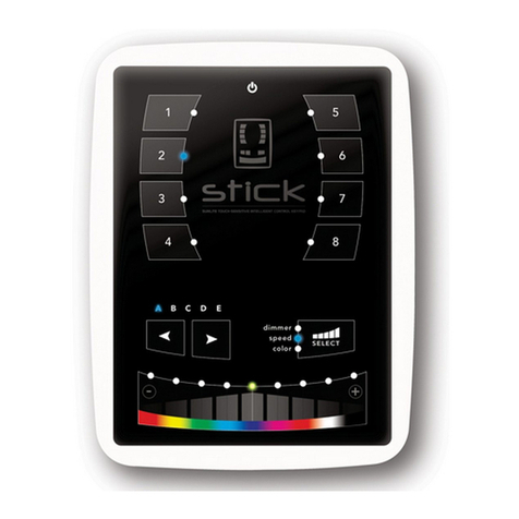
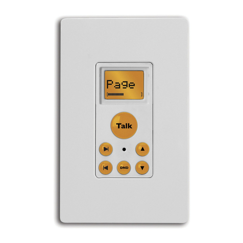
This truly simple controller features an on/o
button at the top, 8 buttons to choose from
up to 200 lighting scenes (25x8), 2 buttons
to cycle between pages and a horizontal
fader to instantly adjust dimmer, speed and
color. Along with a state of the art design, the
product comes with amazing features such as
1024 DMX channels, touch sensitive panel,
clock/calendar, Ethernet facilities, and much
more....
The lighting levels, color and eects can be
programmed from a PC, Mac, Android, iPad or
iPhone using the included software.
Technical Data
Input Power 6-9V DC 0.6A
Output Protocol DMX512 (x2)
Programmability PC, Mac, Tablet,
Smartphone
Available Colors Black
Connections USB, Ethernet,
RS232, Clock, 8 dry
contact ports, Output
Relay
Memory microSD card
4GB max, FAT16/32
Temperature -10 °C to 50 °C
Mounting Single or double gang
wall socket
Dimentions 146x106x11mm
Weight 247g
Standards EC, EMC, ROHS, ETL
Optional Accessories
POWER4M 6V ACDC power supply

www.nicolaudie.com
Sunlite Touch-sensitive Intelligent Control Keypad Ref. STICK-KE2
© Nicolaudie-Sunlite 1989-2019. All rights reserved. We reserve the right without notice to amend the technical information and specications.
Page 2
V 1.9
POWER
DC +
POWER
Ground
DMX
Ground
DMX -
DMX +
1 DMX +
2 DMX -
3 DMX2 +
4 POWER
5 DC +
6 DMX2 -
7 POWER
8 GROUND
POWER
+DMX
1.......8
(
(
Ref: SP485ECN-L
MAX485 CSA
DMX universe #1
DMX universe #2
VIN *
GND
IR_RX
3.3V
Relay
DMX2+
DMX2-
DMX1+
DMX1-
GND_DMX
PORT1
PORT2
PORT3
PORT4
PORT5
PORT6
PORT7
PORT8
RS232 RX
RS232 TX
2 4 6 8 10 12 14 16 18 20
1 3 5 7 9 11 13 15 17 19
Technical datasheet Revision date 10 Jan 2019
2. Connect the wires
POWER: Connect a 6V to 7V DC 0.6A ACDC supply.
Be sure to not invert the + and the ground.
DMX: Connect the DMX cable to the lighting
receivers (Leds, Dimmers, Fixtures..)
(for XLR: 1=ground 2=dmx- 3=dmx+)
3. Mount the interface on the wall
First, mount the back side of the interface on the wall with 2 or
more screws.
Secondly, plug the connectors :
- DMX and power (connector block or RJ45)
- Ethernet cable (allows LAN connection)
The front panel is mounted by pressing it against the back plate
and then sliding down. 2 screws can then be attached under-
neith to hold the prevent removal.
**CHECK PIN CONFIGURATIONS. APPLYING POWER TO THE DMX INPUT WILL DAMAGE THE CONTROLLER**
**MAKE SURE THE CONTROLLER IS MOUNTED WITHOUT TOO MUCH FORCE BEHIND AS THIS CAN PUSH APART THE GLASS**
POWER+DMX
WITH THE
CONNECTOR BLOCK
EASY INSTALLATION
1. Mount an electrical box inside the wall
The controller can be installed in any standard electrical
backbox. If you use a double size box, you can insert
the power supply inside.
POWER+DMX
WITH THE
RJ45 CABLE
Compatible header connectors:
WURTH ELEKTRONIK ref: 61301021121
MOLEX ref: 10-89-7202
TE Connectivity ref: 1-87227-0
FCI ref: 77313-101-20LF
HARWIN ref: M20-9981046
SAMTEC ref: TSW-110-xx-T-D
FARNELL ref: 1841232
RS ref: 763-6754 673-7534 251-8165
MOUSER ref: 538-10-89-7202
DIGIKEY ref: WM26820-ND
2x10 pins EXTENSION socket
DMX CHIP replacement
EXTENSION socket
* VIN pin 20 is not protected and should
not be used

www.nicolaudie.com
Sunlite Touch-sensitive Intelligent Control Keypad Ref. STICK-KE2
© Nicolaudie-Sunlite 1989-2019. All rights reserved. We reserve the right without notice to amend the technical information and specications.
Page 3
V 1.9
11 mm
106 mm
146
mm
1
2
3
4
A B C D E
5
6
7
8
Rechargeable
battery LIR2032
Technical datasheet Revision date 10 Jan 2019
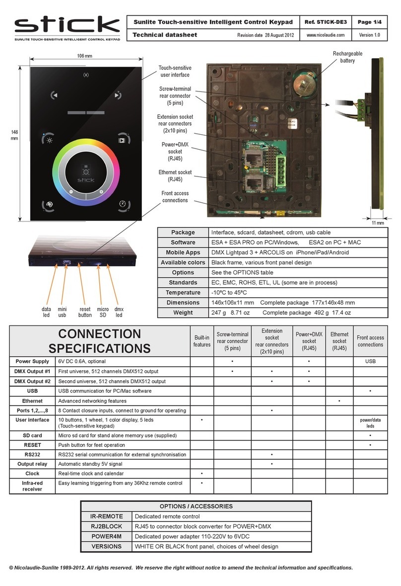
Connections
SPECIFICATIONS / CONNECTIONS Built-in
features
screw-terminal
rear connector
(5 pins)
extension socket
rear connectors
(2x10 pins)
front access
connections
(open cover)
Power Supply 7V DC 0.65A, supplied •USB
DMX Output #1 First universe, 512 channels DMX512 output • •
DMX Output #2 Second universe, 512 channels DMX512 output (*) •
USB USB 2.0 communication for PC/software •
Ethernet Advanced networking features •
Ports 1 - 8 Contact closure inputs, connect to GND to trigger •
User interface 14 buttons, 1 fader, 28 leds (Touch-sensitive keypad) •power/data leds
SDCARD MicroSD card for stand alone memory use (supplied) •
RESET Push button for reset operation •
RS232 RS232 Serial communication for external synchronisation •
Output relay Automatic Stand by 5V signal •
Clock Real time clock and calendar •
Service *To replace the Li-Ion rechargeable battery :
1. You need a rechargeable 3.6v LIR 2032 replacement battery
2. Remove the back panel by pulling down and sliding it out.
3. Using a paper clip push the battery from the bottom so it slides out
of its cage.
4. Slide the replacement battery in from the top, making sure the posi-
tive side is facing up.
5. Replace the back panel by pushing it up into place.
Servicable parts include:
• Memory card - used to store the scenes
• Battery - used to store the clock/calendar
• DMX Chips - used to drive the DMX (see p2.)
Touch-sensitive
user interface
Ethernet socket
(RJ45)
Power+DMX
socket
(RJ45)
Extension socket
rear connectors
(2x10 pins)
Screw-terminal
rear connector
(5 pins)
Front access
connections
mini
usb
reset
button
micro
SD
dmx
led
data
led

www.nicolaudie.com
Sunlite Touch-sensitive Intelligent Control Keypad Ref. STICK-KE2
© Nicolaudie-Sunlite 1989-2019. All rights reserved. We reserve the right without notice to amend the technical information and specications.
ESA Pro Software (Windows) - Timeline + Multi-Zone
https://www.nicolaudie.com/esapro.htm
ESA2 Software (Windows/Mac) - Single Zone
www.nicolaudie.com/esa2.htm
Hardware Manager (Windows/Mac) - Firmware, clock..
www.nicolaudie.com/download.htm
Page 4
V 1.9
P1 P2 P3 P4 ... GND
Make a cable using the 3 pins : TX, RX and G (GND)
Set the RS232 parameters to : 9600bds 8 bits, no Parity, 2 Stop bits
- To play a scene, send 3 bytes : 1 x 255
- To stop a scene, send 3 bytes : 2 x 255
- To pause a scene, send 3 bytes : 3 x 255
- To release a pause, send 3 bytes : 4 x 255
- To reset a scene, send 3 bytes : 5 x 255
The scene number (x) can be from 1 to 40. For instance, 11 means
Page B Scene #3
The controller can be connected to a local network, allowing it to be
controlled from a smartphone or tablet over WiFi.
• Connect the controller to a router or switch with an RJ45 cable
• The controller is set by default to get an IP address from the
router via DHCP. If the network is not working with DHCP, a
manual IP address and subnet mask can be set using the
Hardware Manager
• If the network has a lewall enabled, allow port 2430
The dmx controller can be connected to an existing automation
system over a network and triggered via UDP packet on port 2430.
Use HardwareManager to nd IP address of dmx controller. Refer to
the remote protocol document for more information.
Stick 1 Remote Protocol (PDF)
www.nicolaudie.com/download.htm
Dry Contact Port Triggering
Network Control
UDP Triggering
A relay can be connected between the RELAY and GND sockets of
the 20 pin extension socket. This is an OPEN COLLECTOR OUTPUT
that can drive up to 150mA, 20V. Current ows when the controller
is on and is stopped when in standby.
It can be used to turn o other equipment such as lighting drivers to
save power (see diagram right).
RS232 Triggering
It is possible to start scenes using the input ports (contact closure).
To activate a port, a brief contact of atleast 1/25 second must be
established between the ports (1...8) and the ground (GND). Note:
the scene will not be switched o when the switch is released.
Relay
Example relay : FINDER Ref. 22.23.9.012.4000
Technical datasheet Revision date 10 Jan 2019
The controller be programmed from a PC, Mac, Tablet or
Smartphone using the software available on our website. Refer
to the corresponding software manual for more information. The
rmware can be updated using the Hardware Manager which is
included with the programming software.
Programming the Controller
Setting up the Controller
The controller can be used with one of 3 dierent apps.
Lightpad
Designed to work seamlessly with the controller, Lightpad provides
an easy way to control your lights over a local WiFi network from a
tablet or smartphone. Use the slider to change the dimmer, color or
speed, and the 8 scene buttons to select scenes and eects just like
the wall panel.
www.nicolaudie.com/lightpad.htm
Easy Remote
Create an entirely customized remote controller for your tablet or
smartphone. Easy Remote is a powerful and intuitive app allowing
you to easily add buttons, faders, color wheels and more. Connect to
a WiFi network and the app will nd all compatible devices.
www.nicolaudie.com/easy-remote.htm
Arcolis (Android only)
The Arcolis application is a comprehensive tool allowing you to
directly control and re-program the controller from your smartphone
or tablet. This is a simple application which can be used by just about
everyone in any situation. Mobile, easy to use and powerful, Arcolis
is the ideal controller for dimming or switching traditional, LED and
RGB color mixing DMX lighting xtures. Program static and dynamic
lighting scenes and eects.
iPhone/iPad/Android Control

www.nicolaudie.com
Sunlite Touch-sensitive Intelligent Control Keypad Ref. STICK-KE2
© Nicolaudie-Sunlite 1989-2019. All rights reserved. We reserve the right without notice to amend the technical information and specications.
Page 5
V 1.9
1
2
3
4
A B C D E
5
6
7
8
Some functions are available directly from the controller keypad using the SELECT button.
1
2
3
0
8
7
6
5
4
Select
9
Technical datasheet Revision date 10 Jan 2019
Function Examples
+View time view time 2:45pm = 14:45 = 1445
+ View date view date 6 Sep 2018 = 060918
+Set time
Set time to 3:30pm = 15:30 = press buttons 1530
+Set date
Set 18 DEC 2018 date = 051218
+Set fade
time
Set 1m32s fade time = 0132
+Lock
function
This function locks the keypad (disabled by default)
Use HardwareManager to enable it and set the 4-digit code
+Firmware
version 0121 = rmware version 1.21
1
1 3 05
1
1
8
0 1 3 2
Select
2
Select
3
Select
4
Select
5
Select
6
Select
0
Select 0
5
2
Time Format
3:30pm = 15:30
15:30 = 1530
Date Format
5 DEC 2018 = 051218

www.nicolaudie.com
Sunlite Touch-sensitive Intelligent Control Keypad Ref. STICK-KE2
© Nicolaudie-Sunlite 1989-2019. All rights reserved. We reserve the right without notice to amend the technical information and specications.
Page 6
V 1.9
Technical datasheet Revision date 10 Jan 2019
Troubleshooting
The controller is in Bootloader Mode. This is a special ‘startup mode’
which is run before the main rmware loads.
• Check that there is nothing metallic touching the back of the
controller
• Try re-writing the rmware with the latest HardwareManager
• Try slow formatting SD to FAT16/32 or replacing the card
There is no show le detected on the SD memory card
• Try formatting the SD card in the computer
• Try re-writing the show le
• Try writing the standalone demo show using HardwareManager
• Try replacing the SD memory card
There is no SD card detected
• Check the SD card is properly inserted
• Try formatting the SD card to FAT16/32 in the computer
• Try re-writing the show le
• Try replacing the SD memory card (Max 4Gb)
• Be sure that the latest software version is installed
• Make sure you are using Windows 7, 8 & 10 or OS X 10.8+
• Connect by USB and open the HardwareManager (found in the
software directory). If it’s detected here, try to update the rmware
• If not detected by HardwareManager, the rmware could be
corrupted. This can be solved by forcing a rmware update in
Bootloader Mode
- Load HardwareManager
- Press BootLoader button on the back (see image) and ...
• - Plug-in the USB cable at the same time. If successful the interface
will appear in HardwareManager with the sux ‘_BL’
- Update the rmware
• Check the DMX +, - and GND are connected correctly
• Check that the driver or lighting xture is in DMX mode
• Be sure that the DMX address has been set correctly
• Check there are no more than 32 devices in the chain
• Check that the DMX LED is ickering to the right of the SD card
• Connect with the computer and open HardwareManager (found in
the software directory). Open the DMX Input/Output tab and move
the faders. If your xtures respond here, it is possibly a problem
with the show le
• We strongly recommend the use of a DMX Tester with our interfaces
with any problem solving
• No DMX output? There could be a faulty DMX chip. The has 2 x
DMX chips labelled UDMX1 and UDMX2 which are user-replacable
(see pg2). Try swapping the chips over to test if one is faulty. Use a
at head screw driver to pry them gently from the socket
All LEDs on the controller are ickering
8 scene LEDs are ashing
8 scene and standby LEDs ashing
The controller is not detected by the
computer
Fixtures / lights not responding
The interface is constantly restarting. There could be several causes :
• Corrupt show les. Remove SD card and backup contents. Use
the HardwareManager Standalone screen to write the demo
show. If this solves problem, rewrite your show using the dmx
programming software and .arc or .dlm from your backup.
• Corrupt Firmware. Load HardwareManager and update the
rmware. If not detected, try Bootloader Mode.
• Faulty power supply. Use a multimeter to check the power supply.
The Stick-KE1 and KE2 require 6-7v. The older Stick-KU1, which
used a miniSD card rather than a microSD, requires 9v. Power
supplies do lose the ability to supply voltage over time. If below
specication, replace power supply.
8 scene LEDs cycling constantly
Bootloader
Button
Table of contents
Other Nicolaudie Keypad manuals
