NiCom NTi 300 User manual

NTi 300/600 FM BROADCAST TRANSMITTER


1
INSTALLATION
The installation of any electrical equipment should be made by trained
technicians who know the risks related to handling electrical supplies.
Before proceeding with the installation, it is necessary to verify that the
equipment is in compliance with the rules of the Country where the unit will
operate. Before connecting the transmitter to the AC source, it is necessary to
verify that the voltage range reported in the back of the unit matches the
voltage of the AC supplied. Here are some important details about electrical
systems.
ELECTRICAL SYSTEM
Depending upon the exact location of the site, electricity is subject to more or
less fluctuations in power. Fluctuation in voltage is not the only issue you can
have with electricity. Most of the time, you can have spikes and peaks of
power that last for very short intervals but that are sufficient to destroy your
device. There are many devices on the market that protect the AC line and
they are all useful (surge suppressors, stabilizers etc.). However, only one is
really mandatory to avoid disasters caused by the AC. It is called an
ISOLATION TRASFORMER. The isolation transformer creates a physical
separation from the input of your AC line to the trasmitter. Anything
destructive that would come through the AC, stops in the transformer and
cannot reach the transmitter.
This device is indispensable because, in the last 10 years, the broadcast
industry has developed new smaller power supplies that are very light. They
did this to allow the units to be lighter for easy trasportation. Unfortunately,
the side the downside is that the big transformers that were located inside
the units protecting them, have been removed. The new AC-DC power
supplies do not give any sort of protection. The isolation transformer is
necessary to give that protection. A big isolation transformer installed where
the AC enters the site protect not only one specific device, but all of the
equipment that are in the same building.
If you want to protect only one specific device and you want to know what
size of tranformer you will need, you can multiply the output watt power of
your device by 2.5 and you will have the Watts needed by your isolation
transformer. (Example: for a 1000 W transmitter you need at least a 2.5

2
KWatt isolation transformer). If you want to protect more devices you should
add the wattage of every unit and multiply by 2.5.
Once you have your transformer installed, you need to verify how good your
ground system is. Every good electrician should have a proper device to
measure the ground. Money invested in measuring your ground can fix
problems and avoid bigger expenses in the future. Every rack and every unit
must be connected to ground.
Once that the electrical connections have been verified, you need to connect
the antenna to the transmitter through the coaxial cable. Verify that the
connector is properly tighten and, in case you have a rigid coaxial cable
feeding the transmitter, install a pigtail with proper power capability and more
flexibility so that you do not put too much pressure on the connector.
Before proceeding to operate, we strongly recommend that you make double
sure an adequate grounding system has been set. Nicom will not be held
responsible for damages to persons and materials if these guidelines are not
followed.
The positioning of the transmitter inside the room is equally important. If the
unit is placed in a rack, make sure there is enough space around for the air to
circulate. Remember that fresh air is positioned lowest in the room. Place
your transmitter as low as possible, but not too close to the floor to avoid
damages due to humidity. Leave at least 2 feet of space behind the
transmitter to allow the warm air flow to circulate without obstruction. We
highly recommend to keep the room cool with an air conditioning system, so
that the unit can work at a constant temperature without excessive humidity
(between 60 and 75 degrees); a temperature over 75 degrees causes the unit
to work in a stressed environment which can negatively impact the life and
performance of the unit.

3
CONNECTION AND OPERATION
1. First, connect the transmitting cable coming from the antenna to the
corresponding connector placed in the rear panel of the unit; check that
it is tightened properly.
2. Then connect the plug to the AC mains and also make a good ground
connection.
3. Once these procedures have been performed, you can turn the power
on. The transmitter requires about 20 to 30 seconds to perform the
internal checks and lock onto the frequency. After that, it will start
delivering power.
4. Always start with low power and keep an eye on the reading of the
reflected power to be sure that your system (antenna, cables etc.) is
performing well.
5. Allow the unit to warm up for about 30 minutes and then you can
increase the power to the desired level.
6. Wait another 30 minutes to verify that everything is working properly.
7. Check the air coming out from the rear fans and verify that it is just
warm air not overly hot. At this point, if everything looks good, you can
consider your installation successful.

4
SAFETY SUGGESTIONS
Thank you for your business. We at Nicom appreciate our partnership with you and your
broadcasting team. We proudly stand behind our products. Regardless of how well our
electrical equipment is designed; personnel can be exposed to dangerous electrical shock
when protective covers are removed for maintenance or other activities. Therefore, it is
incumbent on the user to see that all safety regulations are consistently observed and that
each individual assigned to the equipment has a clear understanding of first aid related to
electrical shocks (see next pages).
In addition, these safety practices must be followed:
•Do not attempt to adjust unprotected circuit controls or to dress leads with the
power on.
•Always avoid placing parts of the body in a series between ground and circuit
points.
•To avoid burns, do not touch heavily loaded or overheated components without
precaution.
•Remember that some semiconductor cases and solid-state circuits carry high
voltages.
•Do not assume that all danger of electrical shock is removed when the power is off.
Charged capacitors can retain dangerous voltages for long periods of time after the
power is turned off. These capacitors should be discharged through a suitable
resistor before any circuit points are touched.
•Do not take chances. Be fully trained. Nicom equipment should be operated and
maintained by fully qualified personnel.
•Do not service equipment alone and do not perform internal adjustments to this unit
unless another person is capable of rendering first aid and resuscitation is present.
•Some components used in the construction of this equipment contain Beryllium
Oxide (BeO). This substance is harmless as it is, but becomes highly dangerous if it
is ground to powder. Special procedures of disposal must be observed in case of
failure of these devices.
NOTE: This section is not intended to contain
a complete statement of all safety
precautions that should be observed by personnel in using this electronic
equipment or others.
Nicom shall not be responsible for injury or damage resulted from improper
procedures or from using it by improperly trained or inexperienced personnel.

5
GENERAL INFORMATION FOR SAFETY
When connecting the equipment to power, please follow these important
recommendations:
•This product is intended to operate from a power source that will not apply more
than 10% of the voltage specified on the rear panel between the supply conductors
or between either supply conductor and ground. A protective- ground connection by
way of the grounding conductor in the power cord is essential for safe operation.
•This equipment is grounded through the grounding conductor of the power cord. To
avoid electrical shock, plug the power cord into a properly wired socket before
connecting to the product input or output terminals.
•Upon loss of the protective-ground connection, all accessible conductive parts
(including parts that
may appear to be insulating) can render an electric shock.
•To avoid fire hazard, use only the fuse of correct type, voltage rating, and current
rating. Refer fuse
replacement to qualified service personnel.
•To avoid explosion, do not operate this equipment in an explosive atmosphere.
•To avoid personal injury, do not remove the product covers or panels. Do not
operate the product without the covers and panels properly installed.
GOOD PRACTICE
In maintaining the equipment covered in this manual, please keep in mind the following
standards for good safety practice:
•At regular intervals, the condition of the equipment and the correct functioning of
protective and safety devices shall be checked by a skilled person approved by the
appropriate authority for this duty. Functional checks shall be carried out on
interlocking systems of doors, mechanical interlocks, isolating switches, earthing
switches, parallel resistances and protective devices against overvoltage and over-
currents. The above checks shall not be carried out after the protective and safety
devices have operated under faulty conditions. The safety devices shall not be
altered or disconnected except for replacement, nor shall the safety circuit be
modified without specific approval of the appropriate authority in each case.
•When connecting any instrument (wattmeter, spectrum analyzer, etc.) to a high
frequency output, use the appropriate attenuator or dummy load to protect the final
amplifiers and the instrument input.

6
•When inserting or removing printed circuit boards (PCBs), cable connectors, or
fuses, always turn off power to the affected portion of the equipment. After power is
removed, allow sufficient time for the power supplies to bleed down before
reinserting PCBs.
•When troubleshooting, remember that FETs and other metal-oxide semiconductor
(MOS) devices may appear defective because of leakage between traces or
component leads on the printed circuit board. Clean the printed circuit board and
recheck the MOS device before assuming it is defective.
•When replacing MOS devices, follow standard practices to avoid damage caused
by static charges and soldering.
•When removing components from PCBs (particularly ICs), use care to avoid
damaging PCB traces.
PROCEDURE TO ESTABLISH THE ABSENCE OF VOLTAGE
Follow these simple steps for establish the absence of voltage:
•Before starting work on the equipment, it shall be isolated from the main power
supply. This disconnection shall always be checked by visual inspection. Further
precautions shall be taken to ensure that the main supply cannot be restored while
work is being carried out. After the main supply has been disconnected, all other
lines such as the control, interlocking and modulation lines shall be disconnected if
they carry dangerous voltage. Moreover, the antenna or the antenna transmission
line shall be disconnected from the antenna terminal device to prevent the
introduction of dangerous voltage due to antenna pick-up. When disconnection of
the antenna or antenna transmission line is not possible, other suitable precautions
shall be taken, for example, earthing, when necessary at several places, to
establish absence of voltage. These earthing connections shall be very short
compared with the wave-length.
•Capacitors, which are connected to a circuit isolated from its supply, shall be
discharged (and have their terminals permanently short-circuited, and the casing
earthed) during the whole period of the work.
•The electrical charge retained by electrical machinery when stopped may, in certain
cases, be sufficient to cause a severe shock. This shall be taken into account when
making connections to an apparently "dead" machine. Therefore, all machinery
shall be discharged and earthed using an adequately insulated lead for this
purpose. The discharge operation shall be repeated several times.

7
•Before any maintenance work iscarried out on automatic or remote-controlled
equipment, the remote switching circuits shall be made inoperative.
PROCEDURE FOR DETERMINATION OF THE ABSENCE OF
VOLTAGE
After the equipment has been isolated according to the standard EN60215, the absence of
voltage shall be determined at the work place. This may be done by the use of voltage
indicators, measuring instruments, glow discharge lamps for indicating radio-frequency
voltage or other suitable means.
ELECTRIC SAFETY PRECAUTIONS
All parts making up the equipment have danger identification tags (with a yellow
background) to highlight the parts dangerous for the operator that has access to the
system
. Presence of hazardous energy levels
A hazardous energy level is defined as a stored energy level of 20 J or more, or an
available continuous power level of 240 VA or more, at a potential of 2 V or more.
Precautions for Handling Components Containing Toxic Material
The Beryllium (Beryllium Oxide) is used in the construction of some components of the
apparatus.
This material, when in the form of fine powder or vapor if inhaled into the lungs can cause
respiratory problems. In its solid form, as used herein, can be handled quite safely, but it is
prudent to avoid conditions that favor the formation of dust due to abrasion of the surfaces.
Because of this risk, you should be very careful in the removal and disposal of these
components.
Do not throw them in containers for generic waste material, industrial or domestic, or send
via mail. They must be packed separately and clearly identified in safety and to show the
nature of the risk and then safely disposed by authorized personnel for toxic waste.Before
you remove or replace any RF COMPONENT, make sure that all precautions comply with
the recommendations of SAFETY.
This warning label is used for components containing
Beryllium Oxide.

8
ELECTROSTATIC PRECAUTIONS
Before removing or replacing any PCB assembly within the equipment, make sure that all
precautions comply with ESD protections (ESD = Electro Static Discharge). Make sure that
electrostatic discharge protections are reset after maintenance and/or measurement
operations.
The tag of CAUTION is used for the majority of electronic
devices that are subject to electrical shocks.
If electronic parts have to be touched during installation or repair, please observe the
following precautions.
Operators must be equipped with anti-static protection devices such as:
Elastic wristband: to be fixed on the operator’s wrist.
Flexible cords: to be connected to the elastic wristband and
the
special plug on the shelf highlighted with the ESD
warning label.
9
RULES OF FIRST AID
Personnel engaged in the installation, use and maintenance of the equipment must be
familiar with the theory and practice of first aid.
FIRST AID IN CASE OF ELECTRIC SHOCK
If someone seems unable to free themselves when they receive an electric shock,
disconnect the power before trying to help. A muscle spasm or unconsciousness may
render the victim unable to free themselves from the power source.
If power cannot be turned off immediately, very carefully loop a length of dry non-
conducting material (such as a rope, insulating material, or clothing) around the victim and
pull him free of the power. Carefully avoid touching him or his clothing until free of power.
DO NOT TOUCH VICTIM OR HIS CLOTHING BEFORE POWER IS DISCONNECTED
OR YOU CAN ALSO BECOME A SHOCK VICTIM.
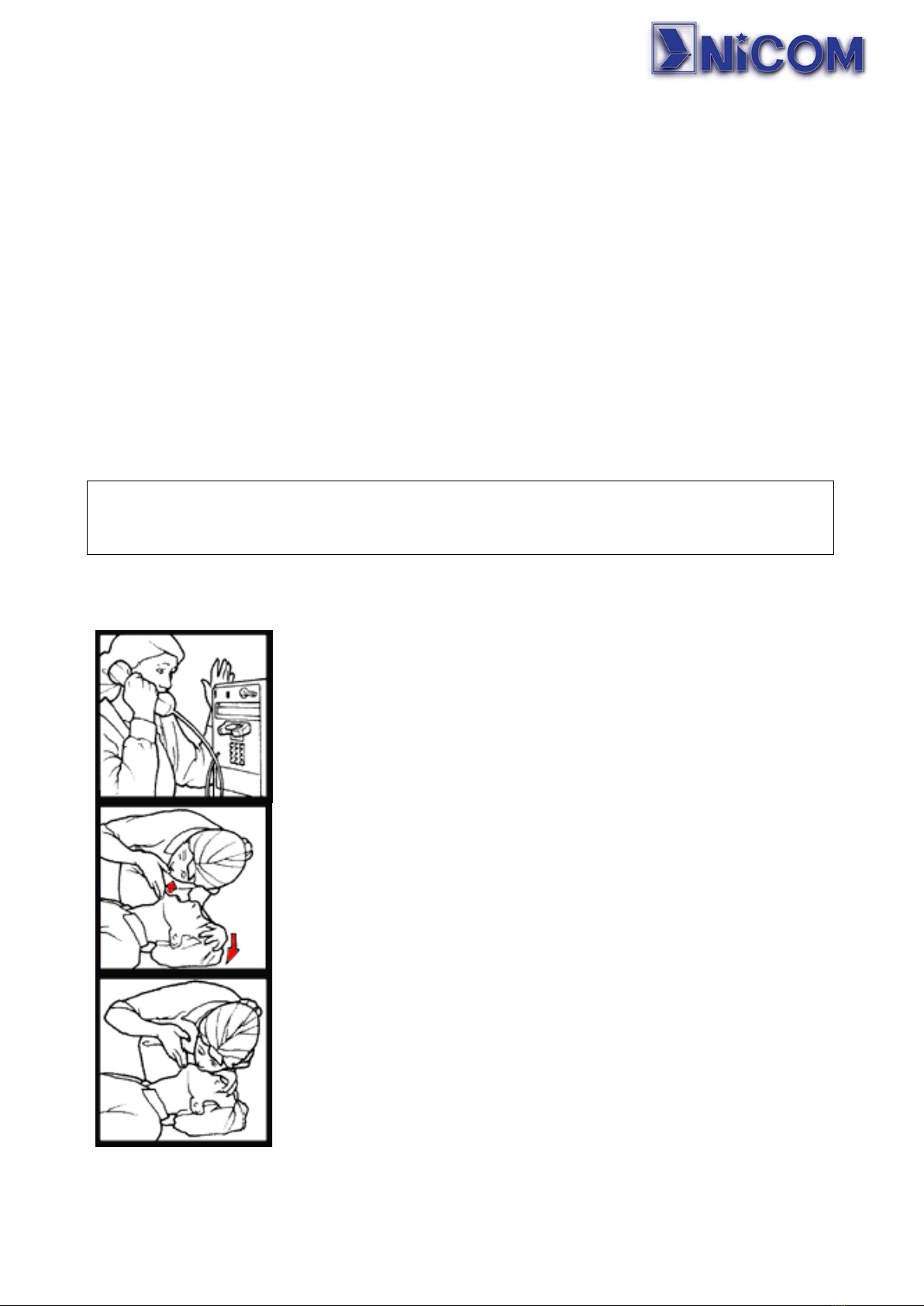
EMERGENCY RESUSCITATION TECHNIQUE
Step 1
Check the victim for unresponsiveness. If there is no response,
immediately call for medical assistance and then return to the
person.
Step 2
Position the person flat on their back. Kneel by their side and
place one hand on the forehead and the other under the chin. Tilt
the head back and lift the chin until teeth almost touch. Look and
listen for breathing.
Step 3
If not breathing normally, pinch the nose and cover the mouth with
yours. Give two full breaths. The person's chest will rise if you are
giving enough air.
10
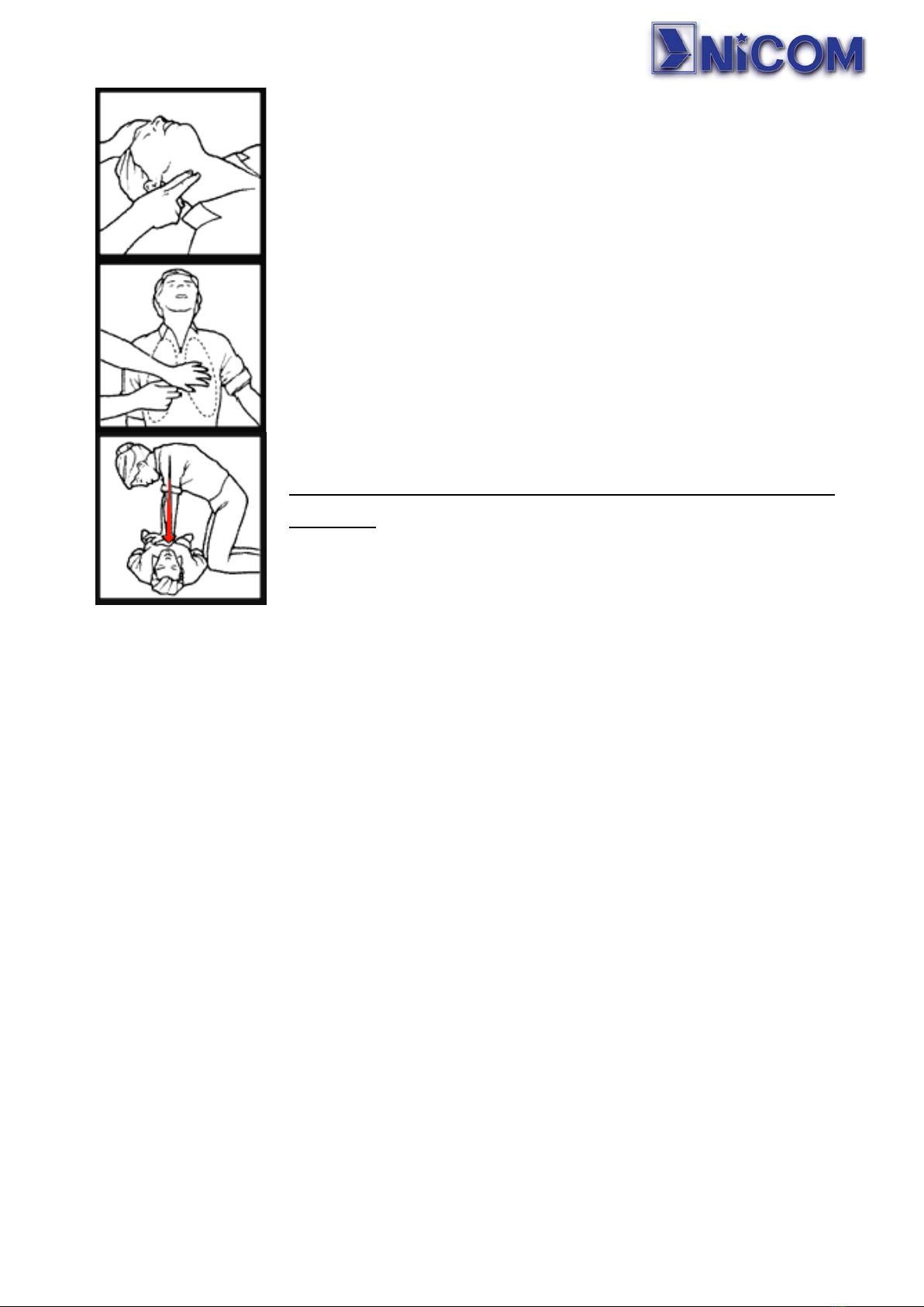
Step 4
Put the fingertips of your hand on the Adam's apple; slide them
into the groove next to the windpipe. Feel for a pulse. If you
cannot feel a pulse or are unsure, move on to the next step.
Step 5
Position your hands in the center of the chest between the
nipples. Place one hand on top of the other.
Step 6
Push down firmly two inches. Push on chest 15 times.
CONTINUE WITH TWO BREATHS AND 15 PUMPS UNTIL HELP
ARRIVES.
TREATMENT FOR BURNS
Extensive burns and broken skin
•Cover area with clean sheet or a clean cloth.
•Do not break blisters, remove tissue, remove any clothing that is stuck to the skin,
and apply an ointment.
•Treat victim according to the type of accident.
•Arrange transportation to a hospital as quickly as possible.
•If arms or legs are affected, keep them elevated.
If medical help is not available within an hour and the victim is conscious and not vomiting,
give a solution of salt and baking soda: 1 teaspoon of salt and half of baking soda every
250 ml of water. Make slowly drink half a glass of solution four times and for a period of 15
minutes.Stop at the retching.Do not administer alcoholic beverages
Less severe burns
•Apply cold gauze compresses (not iced) using a cloth as clean as possible.
•Do not break blisters, remove tissue, remove any clothing that is stuck to the skin,
and apply an ointment.
•If necessary, put on clean clothes and dry.
•Treat victim according to the type of accident.
•Arrange transportation to a hospital as quickly as possible.

11
NTi 300-600 TRANSMITTER FRONT PANEL
The NTi 300 and 600 front panel presents:
1. ON – OFF SWITCH
2. RF MONITOR - RF output of approx.. -50 dBm
3. OLED GRAPHIC DISPLAY
4. ROTARY SWITCH
5. RDS programming input
6. LEDs reporting the status of the unit.
The 3 LEDs close to the rotary switch are like a traffic signal:
•Green indicates regular operation;
•Yellow is a caution alert for a possible issue;
•Red signal stops the machine to protect electronic parts from any damage. After
few minutes the microprocessor will make a second attempt to check if the alarm
condition is still present, if not the unit will resume the power. If not it will try up to
five times and then it will lock the unit in a protection status.
The LEDs on the right give the following indications:
•Internal power supply is running;
•PLL lock status;
•Activation of the final RF module (ON-AIR mode);
•Activation of the STEREO CODER module;
•Activation of the RDS module;
•Activation of RS-485 management
•Activation of the LAN

12
NTi 300-600 TRANSMITTER REAR PANEL
1. POWER SOCKET
2. FUSE HOLDER
3. 80x80x38 48 VDC FANS
4. RF OUTPUT N TYPE CONNECTOR
5. RIGHT CHANNEL STEREO XLR- INPUT
6. LEFT CHANNEL STEREO XLR- INPUT OR MONO (if stereo coder not activated)
7. S/PDIF DIGITAL INPUT
8. MPX INPUT
9. SCA SUBCARRIER 1 INPUT
10.SCA SUBCARRIER 2 INPUT
11.RS485 COM PORT IN-OUT
12.LAN CONNECTION REMOTE CONTROL
13.DB9 TELEMETRY DATA CONNECTOR

13
TURNING ON THE EQUIPMENT
After the unit is switched on the display will show the logo, as it does this, the unit is
performing a test on the signal lights by lighting them for a few seconds.
Then the traffic light LED turns yellow, while the model name is displayed with the
firmware version at the bottom, at the top left you will see the date and on the top right the
time:
During a waiting time of approximately 15 seconds, the PLL module is locking the
programmed frequency
If the lock process is successful, the working frequency is displayed, the traffic light
becomes green, while the LOCK and ON AIR lights indicate that the PLL module and the
RF module are OK:
If a RF power was previously set, the unit will slowly increase the output power until it
reaches the memorized value.
05-01-2016 13:06
Model NTi 5000
Firmware Version 1.02
WAIT
PLL LOCK IN PROGRESS
Frequency 100.000 MHz
RF FWD 250 W –RF RFL
MOD. :
██████████████▐
KHz 0 10 20 30 40 50 60 70 ▲ 80 90

14
Rotating the knob clockwise the reading goes to the main modulation and the MONO
input:
Then it goes to the MPX one:
Then it goes to the STEREO CODER
Then it goes to the SCA1 e SCA2:
Then it goes to the MONO input and to the digital S/PDIF signal.
MOD.:
MONO:
KHz 0 10 20 30 40 50 60 70 ▲ 80 90
dBV -30 -19 -14 -11 -9 -7 -6 -5 -4 -3 -2 -1 0 +1
██████████████▐
█████████████████▐
MOD.:
MPX :
██████████████▐
██████████████▐
██████████████▐
███████████████▐
KHz 0 10 20 30 40 50 60 70 ▲ 80 90
dBV -30 -19 -14 -11 -9 -7 -6 -5 -4 -3 -2 -1 0 +1
MOD.:
RIGHT:
████████████████████████▐
████████████████████▐
██████████████▐
LEFT:
KHz 0 10 20 30 40 50 60 70 ▲ 80 90 100
dBV -30 -19 -14 -11 -9 -7 -6 -5 -4 -3 -2 -1 0 +1 +2
MOD.:
SCA2:
███████████████████████▐
█████████████████▐
███████████████████▐
SCA1:
KHz 0 10 20 30 40 50 60 70 ▲ 80 90 100
dBV -30 -19 -14 -11 -9 -7 -6 -5 -4 -3 -2 -1 0 +1
MOD.:
S/PDIF:
██████████████▐
██████████████▐
KHz 0 10 20 30 40 50 60 70 ▲ 80 90 100
dBV -30 -19 -14 -11 -9 -7 -6 -5 -4 -3 -2 -1 0 +1 +2

15
Then it goes to the digital S/PDIF signal related to the LEFT and RIGHT channels
Then to the RF VOLTAGE and CURRENT module;
Finally, it goes to the internal temperature and the RF module
MOD.:
S/PDIF R:
████████████████████████▐
████████████████████▐
██████████████▐
S/PDIF L:
KHz 0 10 20 30 40 50 60 70 ▲ 80 90 100
dBV -30 -19 -14 -11 -9 -7 -6 -5 -4 -3 -2 -1 0 +1 +2
TEMPERATURE
INTERNAL31.7 °C
RF MODULE 45.5 °C
RF VOLTAGE: = 48.3 V
RF CURRENT:I1 = 24.6 A
I2 = 25.1 A
I3 = 25.3 A

16
SETTING PARAMETERS (PASSWORD DEFAULT: 0 0 0 0)
To access the settings, please press and hold the rotary encoder for a few seconds:
After that you enter the password by selecting the desired number rotating the encoder
and confirming it by pressing the same encoder:
The password is always four digits, at the end of which the unit will ask to confirm by
pressing “ENTER” or exit.
5 attempts are allowed; after that you must turn the machine off and on again to resume
the procedure described above.
ENTER PASSWORD
ENTER PASSWORD
* * * *
ENTER PASSWORD
******
EXIT
ENTER

17
FREQUENCY SETTING
The first line allows you to set the frequency:
Pressing the rotary switch you can choose the frequency steps between 100 KHz or 10
KHz. Then turning the rotary knob you can reach the desired frequency. Confirmation is
done by pressing the rotary encoder for a few seconds.
After confirmation, the RF module is turned off processing a new PLL frequency locking;
The PLL and ON-AIR LEDs are switched on after the locking time is complete. During the
locking time, the traffic light turns yellow and then turns green once the procedure is
complete.
MENU SETUP
3) MONO INPUT
4) MPX INPUT
1) FREQUENCY SETUP
2) RF POWER SETTING
MHz 98.000
FREQUENCY SETUP
100KHz
10KHz
PUSH
FREQUENCY:MHz 88.000
FREQUENCY SETUP
100KHz
10KHz
PUSH
CONFIRM? YES NO
YES
FREQUENCY SETUP
RF FORWARD: 0 W RF FEFLECTED: 0 W
WAIT
PLL LOCK IN PROGRESS

18
OUTPUT POWER SETTING
The second line allows you to set the output RF power:
Rotary encoder rotation allows you to increase or decrease the value of the output RF
power, short rotary pressure allows you to switch from one movement being 10W to many
movements being 100W.
Once the power has been set, it is possible to save it so that in the event of a network
power blackout the system will return to the set value when it is restored:
MENU SETUP
1) FREQUENCY SETUP
2) RF POWER SETTING
3) MONO INPUT
4) MPX INPUT
RF POWER SETTING
RF FWD: 250 W RF RFL: 5 W
POWER: 250 W
RF POWER SETTING
RF FWD: 245 W RF RFL: 5 W
100W
10W
PUSH
100W
CONFIRM? YES NO
10W
This manual suits for next models
1
Table of contents
Other NiCom Transmitter manuals


